💬 Sensebender Gateway
-
@Anticimex @alexsh1 yes should be in other thread. It started with a gateway question and migrated to a signing question. This will be the last one here, since I give up now. I will focus on building a network, and secure it later.
I'm on development branch, so I guess I just need that "specific flag". Couldn't find it in the documentation. I have it set up as the document in doxygen says, and GW should reject unsigned messages or wrong signing, documentation says, but it doesn't... Even nodes that have a different key and MY_SIGNING_ATSHA204 set, talks to the GW and reports temp.
I'll wait until beta is released
@Magnus-Pernemark why do you need the special flag? I just wrote that you only need that if you DON'T want your gw to require signatures from everyone. It works just like @alexsh1 wrote. And it will work like that on both bets and release after release so if you can't get it to work on beta now, it won't work on release later either.
I suggest you start posting some logs so I can see if you really have signing enabled and that all required handshaking takes place. But don't post it in this thread please.Do you feel secure today? No? Start requiring some signatures and feel better tomorrow ;)
-
@Magnus-Pernemark why do you need the special flag? I just wrote that you only need that if you DON'T want your gw to require signatures from everyone. It works just like @alexsh1 wrote. And it will work like that on both bets and release after release so if you can't get it to work on beta now, it won't work on release later either.
I suggest you start posting some logs so I can see if you really have signing enabled and that all required handshaking takes place. But don't post it in this thread please.@Anticimex @alexsh1 It's working now! In one of you replies (@Anticimex ), you misspelled the flag name, and I copy / pasted what you wrote. So all this time, signing was never activated. Now it is and gateway works as expected!
-
@Anticimex @alexsh1 It's working now! In one of you replies (@Anticimex ), you misspelled the flag name, and I copy / pasted what you wrote. So all this time, signing was never activated. Now it is and gateway works as expected!
@Magnus-Pernemark oh, sorry about that. But I do hope the ones in the docs are correct. Good that it works now :+1:
-
This may be a beginner-misunderstanding, but i hope you can assist me.
I had to move one of my repeaters to improve the WAF of my sensor installation.
In this process i may have messed a bit too much with the routing as i think the nodes responds directly to the gateway, but the gateway answers through the repeater. The repeater is moved, and the signal does no longer reach the node, resulting in a head ache (FPAR fails).
I read the debug-section and I think i need to clear my eeprom to allow for a new routing to happen.This proved more difficult than I had anticipated. below is my software stack/process:
- Downloaded Arduino 1.8.3 for non admin install
- Downloaded Mysensors Library v2.1.1 using Library manager
- Downloaded Arduino SAMD Boards (32-bits ARM cortex-M0+) version 1.6.11 using Boards manager
- Downloaded Mysensors SAMD Boards version 1.0.4 using Boards manager
I then rebooted my machine for good measure and uploaded the
ClearEepromConfig-example to the gateway. No output in the serial monitor.I then searched a bit on the forum and added:
#if defined(ARDUINO_ARCH_SAMD)
    while (!Serial) {}
 #endif
In the
setup()-part. This enabled me to get some output from the gateway. Unfortunatly it only returnsStarted clearing. Please wait...I then did some more digging, and apperantly
i2c_eeprom_read_byte()fails. So i searched some more on the forum and found I2C eeprom write fix for SAMD. So i tried the above once again but this time with Mysensors Library v2.2.0-beta (dev branch) just to see if anything changed. It didnt.
What did i miss ? -
Ever since lightning took out my original RFM69 W5100 GW I have been having trouble with the replacement GW I built so now I want to use my Sensebender GW for this instead. On the GW I have allso 4 buttons and 4 relays so my question to @Anticimex is:
Witch pins on the MYSX connector do you recommend for the buttons and relays?
I was thinkin:
Buttons:
MYSX_D1_DFM
MYSX_D2_DTM
MYSX_D3_INT
MYSX_D4_INT
Relays:
MYSX_D5_PWM
MYSX_D6_PWM
MYSX_D9_A3
MYSX_D10_A4Can I assign the pins like this in my sketch:
const int relayPin[] = {MYSX_D5_PWM, MYSX_D6_PWM, MYSX_D9_A3, MYSX_D10_A4};       //  switch around pins to your desire
const int buttonPin[] = {MYSX_D1_DFM, MYSX_D2_DTM, MYSX_D3_INT, MYSX_D4_INT};   //  switch around pins to your desire
Here is the complete sketch, please comment if something can be improved:
/** * The MySensors Arduino library handles the wireless radio link and protocol * between your home built sensors/actuators and HA controller of choice. * The sensors forms a self healing radio network with optional repeaters. Each * repeater and gateway builds a routing tables in EEPROM which keeps track of the * network topology allowing messages to be routed to nodes. * * Created by Henrik Ekblad <henrik.ekblad@mysensors.org> * Copyright (C) 2013-2015 Sensnology AB * Full contributor list: https://github.com/mysensors/Arduino/graphs/contributors * * Documentation: http://www.mysensors.org * Support Forum: http://forum.mysensors.org * * This program is free software; you can redistribute it and/or * modify it under the terms of the GNU General Public License * version 2 as published by the Free Software Foundation. * ******************************* * * REVISION HISTORY * Version 1.0 - Henrik EKblad * Contribution by a-lurker and Anticimex, * Contribution by Norbert Truchsess <norbert.truchsess@t-online.de> * Contribution by Tomas Hozza <thozza@gmail.com> * * * DESCRIPTION * The EthernetGateway sends data received from sensors to the ethernet link. * The gateway also accepts input on ethernet interface, which is then sent out to the radio network. * * The GW code is designed for Arduino 328p / 16MHz. ATmega168 does not have enough memory to run this program. * * LED purposes: * - To use the feature, uncomment MY_DEFAULT_xxx_LED_PIN in the sketch below * - RX (green) - blink fast on radio message recieved. In inclusion mode will blink fast only on presentation recieved * - TX (yellow) - blink fast on radio message transmitted. In inclusion mode will blink slowly * - ERR (red) - fast blink on error during transmission error or recieve crc error * * See http://www.mysensors.org/build/ethernet_gateway for wiring instructions. * */ // Enable debug prints to serial monitor #define MY_DEBUG #define SN "EthGW/RFM69 Rele Button" #define SV "1.5" // Enable and select radio type attached //#define MY_RADIO_NRF24 //#define MY_RADIO_NRF5_ESB #define MY_RADIO_RFM69 #define MY_RFM69_FREQUENCY RF69_433MHZ #define MY_IS_RFM69HW //#define MY_RADIO_RFM95 // Enable gateway ethernet module type #define MY_GATEWAY_W5100 // W5100 Ethernet module SPI enable (optional if using a shield/module that manages SPI_EN signal) //#define MY_W5100_SPI_EN 4 // Enable Soft SPI for NRF radio (note different radio wiring is required) // The W5100 ethernet module seems to have a hard time co-operate with // radio on the same spi bus. #if !defined(MY_W5100_SPI_EN) && !defined(ARDUINO_ARCH_SAMD) #define MY_SOFTSPI #define MY_SOFT_SPI_SCK_PIN 14 #define MY_SOFT_SPI_MISO_PIN 16 #define MY_SOFT_SPI_MOSI_PIN 15 #endif // When W5100 is connected we have to move CE/CSN pins for NRF radio #ifndef MY_RF24_CE_PIN #define MY_RF24_CE_PIN 5 #endif #ifndef MY_RF24_CS_PIN #define MY_RF24_CS_PIN 6 #endif // Enable UDP communication //#define MY_USE_UDP // If using UDP you need to set MY_CONTROLLER_IP_ADDRESS below // Enable MY_IP_ADDRESS here if you want a static ip address (no DHCP) #define MY_IP_ADDRESS 192,168,1,100 // If using static ip you can define Gateway and Subnet address as well //#define MY_IP_GATEWAY_ADDRESS 192,168,178,1 //#define MY_IP_SUBNET_ADDRESS 255,255,255,0 // Renewal period if using DHCP //#define MY_IP_RENEWAL_INTERVAL 60000 // The port to keep open on node server mode / or port to contact in client mode #define MY_PORT 5003 // Controller ip address. Enables client mode (default is "server" mode). // Also enable this if MY_USE_UDP is used and you want sensor data sent somewhere. //#define MY_CONTROLLER_IP_ADDRESS 192, 168, 178, 254 // The MAC address can be anything you want but should be unique on your network. // Newer boards have a MAC address printed on the underside of the PCB, which you can (optionally) use. // Note that most of the Ardunio examples use "DEAD BEEF FEED" for the MAC address. #define MY_MAC_ADDRESS 0xDE, 0xAD, 0xBE, 0xEF, 0xED, 0xED // Enable inclusion mode #define MY_INCLUSION_MODE_FEATURE // Enable Inclusion mode button on gateway //#define MY_INCLUSION_BUTTON_FEATURE // Set inclusion mode duration (in seconds) #define MY_INCLUSION_MODE_DURATION 60 // Digital pin used for inclusion mode button //#define MY_INCLUSION_MODE_BUTTON_PIN 3 // Set blinking period #define MY_DEFAULT_LED_BLINK_PERIOD 300 // Flash leds on rx/tx/err // Uncomment to override default HW configurations //#define MY_DEFAULT_ERR_LED_PIN 7 // Error led pin //#define MY_DEFAULT_RX_LED_PIN 8 // Receive led pin //#define MY_DEFAULT_TX_LED_PIN 9 // Transmit led pin #if defined(MY_USE_UDP) #include <EthernetUdp.h> #endif #include <Ethernet.h> #include <MySensors.h> #include <Bounce2.h> #define RELAY_ON 0 // switch around for ACTIVE LOW / ACTIVE HIGH relay #define RELAY_OFF 1 // #define noRelays 4 //2-4 const int relayPin[] = {MYSX_D5_PWM, MYSX_D6_PWM, MYSX_D9_A3, MYSX_D10_A4}; // switch around pins to your desire const int buttonPin[] = {MYSX_D1_DFM, MYSX_D2_DTM, MYSX_D3_INT, MYSX_D4_INT}; // switch around pins to your desire class Relay // relay class, store all relevant data (equivalent to struct) { public: int buttonPin; // physical pin number of button int relayPin; // physical pin number of relay boolean relayState; // relay status (also stored in EEPROM) }; Relay Relays[noRelays]; Bounce debouncer[noRelays]; MyMessage msg[noRelays]; void setup() { // Setup locally attached sensors wait(100); // Initialize Relays with corresponding buttons for (int i = 0; i < noRelays; i++) { Relays[i].buttonPin = buttonPin[i]; // assign physical pins Relays[i].relayPin = relayPin[i]; msg[i].sensor = i; // initialize messages msg[i].type = V_LIGHT; pinMode(Relays[i].buttonPin, INPUT_PULLUP); wait(100); pinMode(Relays[i].relayPin, OUTPUT); Relays[i].relayState = loadState(i); // retrieve last values from EEPROM digitalWrite(Relays[i].relayPin, Relays[i].relayState ? RELAY_ON : RELAY_OFF); // and set relays accordingly send(msg[i].set(Relays[i].relayState ? true : false)); // make controller aware of last status wait(50); debouncer[i] = Bounce(); // initialize debouncer debouncer[i].attach(buttonPin[i]); debouncer[i].interval(30); wait(50); } } void presentation() { // Present locally attached sensors here // Send the sketch version information to the gateway and Controller sendSketchInfo(SN, SV); wait(100); for (int i = 0; i < noRelays; i++) present(i, S_LIGHT); // present sensor to gateway wait(100); } void loop() { // Send locally attached sensors data here for (byte i = 0; i < noRelays; i++) { if (debouncer[i].update()) { int value = debouncer[i].read(); if ( value == LOW) { Relays[i].relayState = !Relays[i].relayState; digitalWrite(Relays[i].relayPin, Relays[i].relayState ? RELAY_ON : RELAY_OFF); send(msg[i].set(Relays[i].relayState ? true : false)); // save sensor state in EEPROM (location == sensor number) saveState( i, Relays[i].relayState ); } } } //wait(20); } void receive(const MyMessage &message) { if (message.sender == 0) { if (message.type == V_LIGHT) { if (message.sensor < noRelays) { // check if message is valid for relays..... previous line [[[ if (message.sensor <=noRelays){ ]]] Relays[message.sensor].relayState = message.getBool(); digitalWrite(Relays[message.sensor].relayPin, Relays[message.sensor].relayState ? RELAY_ON : RELAY_OFF); // and set relays accordingly saveState( message.sensor, Relays[message.sensor].relayState ); // save sensor state in EEPROM (location == sensor number) } } } wait(20); }- Tomas
-
Ever since lightning took out my original RFM69 W5100 GW I have been having trouble with the replacement GW I built so now I want to use my Sensebender GW for this instead. On the GW I have allso 4 buttons and 4 relays so my question to @Anticimex is:
Witch pins on the MYSX connector do you recommend for the buttons and relays?
I was thinkin:
Buttons:
MYSX_D1_DFM
MYSX_D2_DTM
MYSX_D3_INT
MYSX_D4_INT
Relays:
MYSX_D5_PWM
MYSX_D6_PWM
MYSX_D9_A3
MYSX_D10_A4Can I assign the pins like this in my sketch:
const int relayPin[] = {MYSX_D5_PWM, MYSX_D6_PWM, MYSX_D9_A3, MYSX_D10_A4};       //  switch around pins to your desire
const int buttonPin[] = {MYSX_D1_DFM, MYSX_D2_DTM, MYSX_D3_INT, MYSX_D4_INT};   //  switch around pins to your desire
Here is the complete sketch, please comment if something can be improved:
/** * The MySensors Arduino library handles the wireless radio link and protocol * between your home built sensors/actuators and HA controller of choice. * The sensors forms a self healing radio network with optional repeaters. Each * repeater and gateway builds a routing tables in EEPROM which keeps track of the * network topology allowing messages to be routed to nodes. * * Created by Henrik Ekblad <henrik.ekblad@mysensors.org> * Copyright (C) 2013-2015 Sensnology AB * Full contributor list: https://github.com/mysensors/Arduino/graphs/contributors * * Documentation: http://www.mysensors.org * Support Forum: http://forum.mysensors.org * * This program is free software; you can redistribute it and/or * modify it under the terms of the GNU General Public License * version 2 as published by the Free Software Foundation. * ******************************* * * REVISION HISTORY * Version 1.0 - Henrik EKblad * Contribution by a-lurker and Anticimex, * Contribution by Norbert Truchsess <norbert.truchsess@t-online.de> * Contribution by Tomas Hozza <thozza@gmail.com> * * * DESCRIPTION * The EthernetGateway sends data received from sensors to the ethernet link. * The gateway also accepts input on ethernet interface, which is then sent out to the radio network. * * The GW code is designed for Arduino 328p / 16MHz. ATmega168 does not have enough memory to run this program. * * LED purposes: * - To use the feature, uncomment MY_DEFAULT_xxx_LED_PIN in the sketch below * - RX (green) - blink fast on radio message recieved. In inclusion mode will blink fast only on presentation recieved * - TX (yellow) - blink fast on radio message transmitted. In inclusion mode will blink slowly * - ERR (red) - fast blink on error during transmission error or recieve crc error * * See http://www.mysensors.org/build/ethernet_gateway for wiring instructions. * */ // Enable debug prints to serial monitor #define MY_DEBUG #define SN "EthGW/RFM69 Rele Button" #define SV "1.5" // Enable and select radio type attached //#define MY_RADIO_NRF24 //#define MY_RADIO_NRF5_ESB #define MY_RADIO_RFM69 #define MY_RFM69_FREQUENCY RF69_433MHZ #define MY_IS_RFM69HW //#define MY_RADIO_RFM95 // Enable gateway ethernet module type #define MY_GATEWAY_W5100 // W5100 Ethernet module SPI enable (optional if using a shield/module that manages SPI_EN signal) //#define MY_W5100_SPI_EN 4 // Enable Soft SPI for NRF radio (note different radio wiring is required) // The W5100 ethernet module seems to have a hard time co-operate with // radio on the same spi bus. #if !defined(MY_W5100_SPI_EN) && !defined(ARDUINO_ARCH_SAMD) #define MY_SOFTSPI #define MY_SOFT_SPI_SCK_PIN 14 #define MY_SOFT_SPI_MISO_PIN 16 #define MY_SOFT_SPI_MOSI_PIN 15 #endif // When W5100 is connected we have to move CE/CSN pins for NRF radio #ifndef MY_RF24_CE_PIN #define MY_RF24_CE_PIN 5 #endif #ifndef MY_RF24_CS_PIN #define MY_RF24_CS_PIN 6 #endif // Enable UDP communication //#define MY_USE_UDP // If using UDP you need to set MY_CONTROLLER_IP_ADDRESS below // Enable MY_IP_ADDRESS here if you want a static ip address (no DHCP) #define MY_IP_ADDRESS 192,168,1,100 // If using static ip you can define Gateway and Subnet address as well //#define MY_IP_GATEWAY_ADDRESS 192,168,178,1 //#define MY_IP_SUBNET_ADDRESS 255,255,255,0 // Renewal period if using DHCP //#define MY_IP_RENEWAL_INTERVAL 60000 // The port to keep open on node server mode / or port to contact in client mode #define MY_PORT 5003 // Controller ip address. Enables client mode (default is "server" mode). // Also enable this if MY_USE_UDP is used and you want sensor data sent somewhere. //#define MY_CONTROLLER_IP_ADDRESS 192, 168, 178, 254 // The MAC address can be anything you want but should be unique on your network. // Newer boards have a MAC address printed on the underside of the PCB, which you can (optionally) use. // Note that most of the Ardunio examples use "DEAD BEEF FEED" for the MAC address. #define MY_MAC_ADDRESS 0xDE, 0xAD, 0xBE, 0xEF, 0xED, 0xED // Enable inclusion mode #define MY_INCLUSION_MODE_FEATURE // Enable Inclusion mode button on gateway //#define MY_INCLUSION_BUTTON_FEATURE // Set inclusion mode duration (in seconds) #define MY_INCLUSION_MODE_DURATION 60 // Digital pin used for inclusion mode button //#define MY_INCLUSION_MODE_BUTTON_PIN 3 // Set blinking period #define MY_DEFAULT_LED_BLINK_PERIOD 300 // Flash leds on rx/tx/err // Uncomment to override default HW configurations //#define MY_DEFAULT_ERR_LED_PIN 7 // Error led pin //#define MY_DEFAULT_RX_LED_PIN 8 // Receive led pin //#define MY_DEFAULT_TX_LED_PIN 9 // Transmit led pin #if defined(MY_USE_UDP) #include <EthernetUdp.h> #endif #include <Ethernet.h> #include <MySensors.h> #include <Bounce2.h> #define RELAY_ON 0 // switch around for ACTIVE LOW / ACTIVE HIGH relay #define RELAY_OFF 1 // #define noRelays 4 //2-4 const int relayPin[] = {MYSX_D5_PWM, MYSX_D6_PWM, MYSX_D9_A3, MYSX_D10_A4}; // switch around pins to your desire const int buttonPin[] = {MYSX_D1_DFM, MYSX_D2_DTM, MYSX_D3_INT, MYSX_D4_INT}; // switch around pins to your desire class Relay // relay class, store all relevant data (equivalent to struct) { public: int buttonPin; // physical pin number of button int relayPin; // physical pin number of relay boolean relayState; // relay status (also stored in EEPROM) }; Relay Relays[noRelays]; Bounce debouncer[noRelays]; MyMessage msg[noRelays]; void setup() { // Setup locally attached sensors wait(100); // Initialize Relays with corresponding buttons for (int i = 0; i < noRelays; i++) { Relays[i].buttonPin = buttonPin[i]; // assign physical pins Relays[i].relayPin = relayPin[i]; msg[i].sensor = i; // initialize messages msg[i].type = V_LIGHT; pinMode(Relays[i].buttonPin, INPUT_PULLUP); wait(100); pinMode(Relays[i].relayPin, OUTPUT); Relays[i].relayState = loadState(i); // retrieve last values from EEPROM digitalWrite(Relays[i].relayPin, Relays[i].relayState ? RELAY_ON : RELAY_OFF); // and set relays accordingly send(msg[i].set(Relays[i].relayState ? true : false)); // make controller aware of last status wait(50); debouncer[i] = Bounce(); // initialize debouncer debouncer[i].attach(buttonPin[i]); debouncer[i].interval(30); wait(50); } } void presentation() { // Present locally attached sensors here // Send the sketch version information to the gateway and Controller sendSketchInfo(SN, SV); wait(100); for (int i = 0; i < noRelays; i++) present(i, S_LIGHT); // present sensor to gateway wait(100); } void loop() { // Send locally attached sensors data here for (byte i = 0; i < noRelays; i++) { if (debouncer[i].update()) { int value = debouncer[i].read(); if ( value == LOW) { Relays[i].relayState = !Relays[i].relayState; digitalWrite(Relays[i].relayPin, Relays[i].relayState ? RELAY_ON : RELAY_OFF); send(msg[i].set(Relays[i].relayState ? true : false)); // save sensor state in EEPROM (location == sensor number) saveState( i, Relays[i].relayState ); } } } //wait(20); } void receive(const MyMessage &message) { if (message.sender == 0) { if (message.type == V_LIGHT) { if (message.sensor < noRelays) { // check if message is valid for relays..... previous line [[[ if (message.sensor <=noRelays){ ]]] Relays[message.sensor].relayState = message.getBool(); digitalWrite(Relays[message.sensor].relayPin, Relays[message.sensor].relayState ? RELAY_ON : RELAY_OFF); // and set relays accordingly saveState( message.sensor, Relays[message.sensor].relayState ); // save sensor state in EEPROM (location == sensor number) } } } wait(20); }@korttoma you can use any pin that can provide the type of functionality you need (for example, don't expect that using an analog pin for digital data to work). Just keep in mind that by using certain pins, you might have to give up features you might like to use later on (like in this case you take the dfm and dtm pins, so you have "taken" the UART pins if you ever plan to use that for your board).
As for the definitions, I am not sure. @tbowmo made the mappings for that port. I believe it looks good. -
@korttoma
Like @anticimex said, you will loose possibility of using the serial port if you use the dtm/dfm lines.But besides that, you are free to use all the ports as digital input/output, except the i2c pins as we have an i2c eeprom that is connected to the same pins.
-
Thanks @Anticimex and @tbowmo I have the GW up and running with one external sensor now. I just need to connect the buttons and relays to test those.
I'm not sure if I will ever need the UART pins but I will make the hardware so that I can easily change the pins used for buttons and relays.
btw, what is the use cases for UART pins?
- Tomas
-
Thanks @Anticimex and @tbowmo I have the GW up and running with one external sensor now. I just need to connect the buttons and relays to test those.
I'm not sure if I will ever need the UART pins but I will make the hardware so that I can easily change the pins used for buttons and relays.
btw, what is the use cases for UART pins?
@korttoma if you have peripherals on your daughter board that communicate using a serial protocol it makes sense to leverage any hw UART capable blocks on the main board. The MYSX standard just indicate that if the main board has such capability, the interface is available on those two pins. You can of course bit bang it on any digital io (depending on core clock) if you need several interfaces.
-
Thanks @Anticimex and @tbowmo I have the GW up and running with one external sensor now. I just need to connect the buttons and relays to test those.
I'm not sure if I will ever need the UART pins but I will make the hardware so that I can easily change the pins used for buttons and relays.
btw, what is the use cases for UART pins?
-
Button and relay pins I assigned seem to work correctly but now I managed to release some magic smoke from the Sensebender GW board :( shorted something by mistake and at least FB1 is tost. Can I just shor FB1 to see if the board is stil alive or do I have to replace FB1? Seems like nothing else was damaged (at least I hope so) since it was GND and Vraw that was shorted.
Edit: Just confirmed that it is only FB1 that was destroyed the rest seems to work :D just cant power it from the USB anymore. Hope I can stil write to it.
- Tomas
-
Button and relay pins I assigned seem to work correctly but now I managed to release some magic smoke from the Sensebender GW board :( shorted something by mistake and at least FB1 is tost. Can I just shor FB1 to see if the board is stil alive or do I have to replace FB1? Seems like nothing else was damaged (at least I hope so) since it was GND and Vraw that was shorted.
Edit: Just confirmed that it is only FB1 that was destroyed the rest seems to work :D just cant power it from the USB anymore. Hope I can stil write to it.
@korttoma said in 💬 Sensebender Gateway:
Button and relay pins I assigned seem to work correctly but now I managed to release some magic smoke from the Sensebender GW board :( shorted something by mistake and at least FB1 is tost. Can I just shor FB1 to see if the board is stil alive or do I have to replace FB1? Seems like nothing else was damaged (at least I hope so) since it was GND and Vraw that was shorted.
Edit: Just confirmed that it is only FB1 that was destroyed the rest seems to work :D just cant power it from the USB anymore. Hope I can stil write to it.
FB1 is just a filter to suppress spurious RF (if any) on the gnd wire exiting the board. So it can be shorted. The gateway should function fine without it.
-
Hi All,
I have purchased a SenseBender Gateway, tested the MySensors MQTT code etc on it and thats all good.
Now I want to experiment with my own code on it. I notice that in the example code there are some references to the onboard LEDs, such as;static uint8_t leds[] = {LED_BLUE, LED_RED, LED_GREEN, LED_YELLOW, LED_ORANGE};
which is great, I will use those to manage the LEDs in my sketch.
What I'd like to know is where are LED_BLUE, LED_RED etc actually defined? What file? The reason I ask is that I also want to know which pin is connected to the RFM69 RESET pin. On the schematic for the SenseBender it is labelled RESET_RFM on the SAMD21 chip, and is physical chip pin 23 and also PB10. I don't know how to use that in my sketch, so if I had a macro like there is for the LEDs then I could just call that.
I'm assuming that if I find where LED_BLUE is defined I may find info about the other pins I also want to use :)Thanks,
Paul -
-
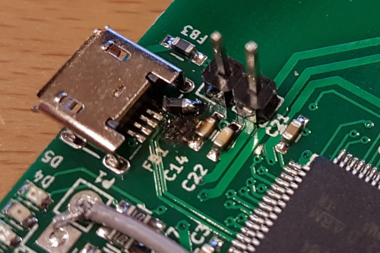
Received a new ferrite bead and soldered it to my device. The bead showed 0 ohm with a multimeter so I don't know if it is the real deal but it seems to work even if it is not pretty:
-
at DC it should be close to 0 ohm, but on higher frequencies it should act as a resistor.
btw. it seems like the old one had exploded? :)
@tbowmo said in 💬 Sensebender Gateway:
it seems like the old one had exploded?
That's what happens when you short Vraw to GND on the MYSX connector in one of those facepalm moments :D (we need an :facepalm emoji!).