💬 Sensebender Gateway
-
@korttoma
Like @anticimex said, you will loose possibility of using the serial port if you use the dtm/dfm lines.But besides that, you are free to use all the ports as digital input/output, except the i2c pins as we have an i2c eeprom that is connected to the same pins.
-
Thanks @Anticimex and @tbowmo I have the GW up and running with one external sensor now. I just need to connect the buttons and relays to test those.
I'm not sure if I will ever need the UART pins but I will make the hardware so that I can easily change the pins used for buttons and relays.
btw, what is the use cases for UART pins?
- Tomas
-
Thanks @Anticimex and @tbowmo I have the GW up and running with one external sensor now. I just need to connect the buttons and relays to test those.
I'm not sure if I will ever need the UART pins but I will make the hardware so that I can easily change the pins used for buttons and relays.
btw, what is the use cases for UART pins?
@korttoma if you have peripherals on your daughter board that communicate using a serial protocol it makes sense to leverage any hw UART capable blocks on the main board. The MYSX standard just indicate that if the main board has such capability, the interface is available on those two pins. You can of course bit bang it on any digital io (depending on core clock) if you need several interfaces.
-
Thanks @Anticimex and @tbowmo I have the GW up and running with one external sensor now. I just need to connect the buttons and relays to test those.
I'm not sure if I will ever need the UART pins but I will make the hardware so that I can easily change the pins used for buttons and relays.
btw, what is the use cases for UART pins?
-
Button and relay pins I assigned seem to work correctly but now I managed to release some magic smoke from the Sensebender GW board :( shorted something by mistake and at least FB1 is tost. Can I just shor FB1 to see if the board is stil alive or do I have to replace FB1? Seems like nothing else was damaged (at least I hope so) since it was GND and Vraw that was shorted.
Edit: Just confirmed that it is only FB1 that was destroyed the rest seems to work :D just cant power it from the USB anymore. Hope I can stil write to it.
- Tomas
-
Button and relay pins I assigned seem to work correctly but now I managed to release some magic smoke from the Sensebender GW board :( shorted something by mistake and at least FB1 is tost. Can I just shor FB1 to see if the board is stil alive or do I have to replace FB1? Seems like nothing else was damaged (at least I hope so) since it was GND and Vraw that was shorted.
Edit: Just confirmed that it is only FB1 that was destroyed the rest seems to work :D just cant power it from the USB anymore. Hope I can stil write to it.
@korttoma said in 💬 Sensebender Gateway:
Button and relay pins I assigned seem to work correctly but now I managed to release some magic smoke from the Sensebender GW board :( shorted something by mistake and at least FB1 is tost. Can I just shor FB1 to see if the board is stil alive or do I have to replace FB1? Seems like nothing else was damaged (at least I hope so) since it was GND and Vraw that was shorted.
Edit: Just confirmed that it is only FB1 that was destroyed the rest seems to work :D just cant power it from the USB anymore. Hope I can stil write to it.
FB1 is just a filter to suppress spurious RF (if any) on the gnd wire exiting the board. So it can be shorted. The gateway should function fine without it.
-
Hi All,
I have purchased a SenseBender Gateway, tested the MySensors MQTT code etc on it and thats all good.
Now I want to experiment with my own code on it. I notice that in the example code there are some references to the onboard LEDs, such as;static uint8_t leds[] = {LED_BLUE, LED_RED, LED_GREEN, LED_YELLOW, LED_ORANGE};
which is great, I will use those to manage the LEDs in my sketch.
What I'd like to know is where are LED_BLUE, LED_RED etc actually defined? What file? The reason I ask is that I also want to know which pin is connected to the RFM69 RESET pin. On the schematic for the SenseBender it is labelled RESET_RFM on the SAMD21 chip, and is physical chip pin 23 and also PB10. I don't know how to use that in my sketch, so if I had a macro like there is for the LEDs then I could just call that.
I'm assuming that if I find where LED_BLUE is defined I may find info about the other pins I also want to use :)Thanks,
Paul -
-
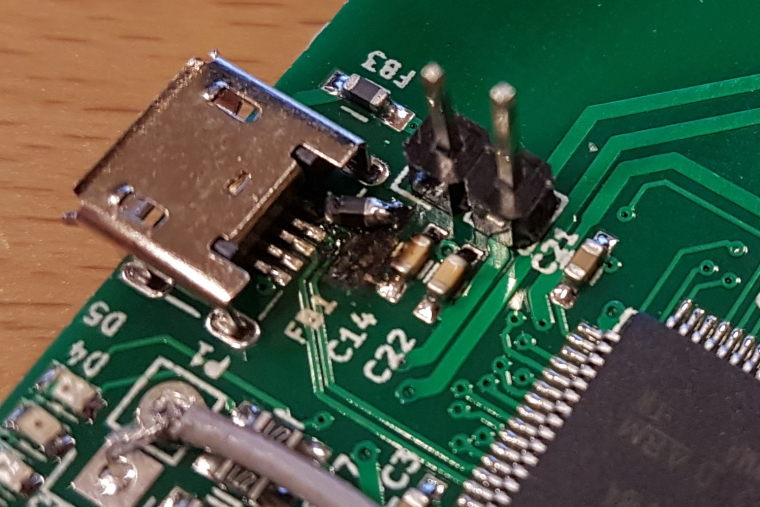
Received a new ferrite bead and soldered it to my device. The bead showed 0 ohm with a multimeter so I don't know if it is the real deal but it seems to work even if it is not pretty:
-
at DC it should be close to 0 ohm, but on higher frequencies it should act as a resistor.
btw. it seems like the old one had exploded? :)
@tbowmo said in 💬 Sensebender Gateway:
it seems like the old one had exploded?
That's what happens when you short Vraw to GND on the MYSX connector in one of those facepalm moments :D (we need an :facepalm emoji!).

-
I have a lot of problem with this gateway. First I think it was caused by network module but with serial sketch I have a lot of issues. After 2 or 3 days, gateway crash. If I remove some sensors reporting every 30 seconds it crash but later.
This morning, all leds are off on the board. After powering off and on it was ok.
I'im using RFM69 with Openhab2 as controller.
Is someone experience same issue ? I will fall back to my old Jeelink gateway (ATmega328 based).