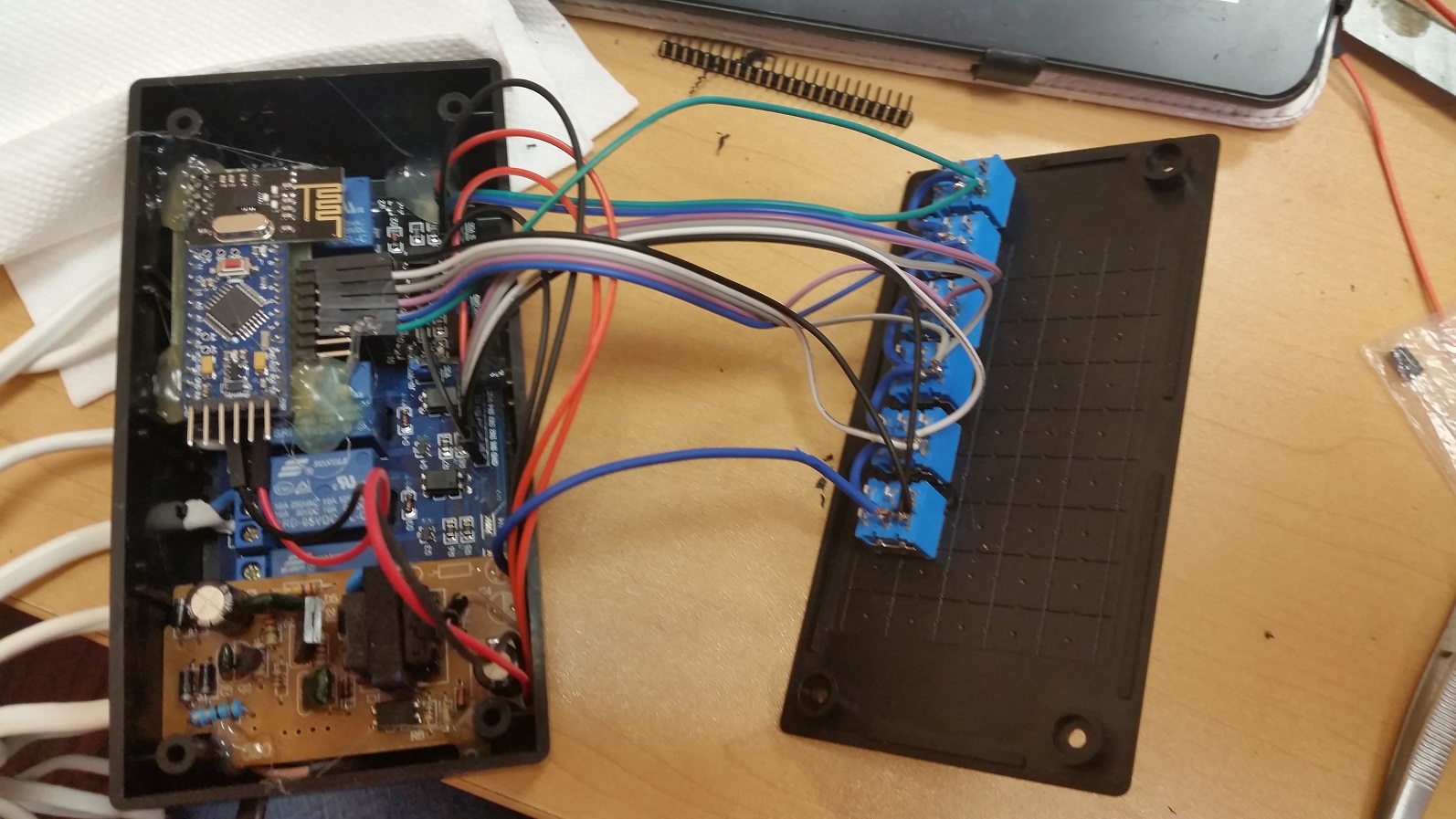
RelayWithButtonActuator (6 channel)
-
PARTS LIST:
Relays (6 channel)
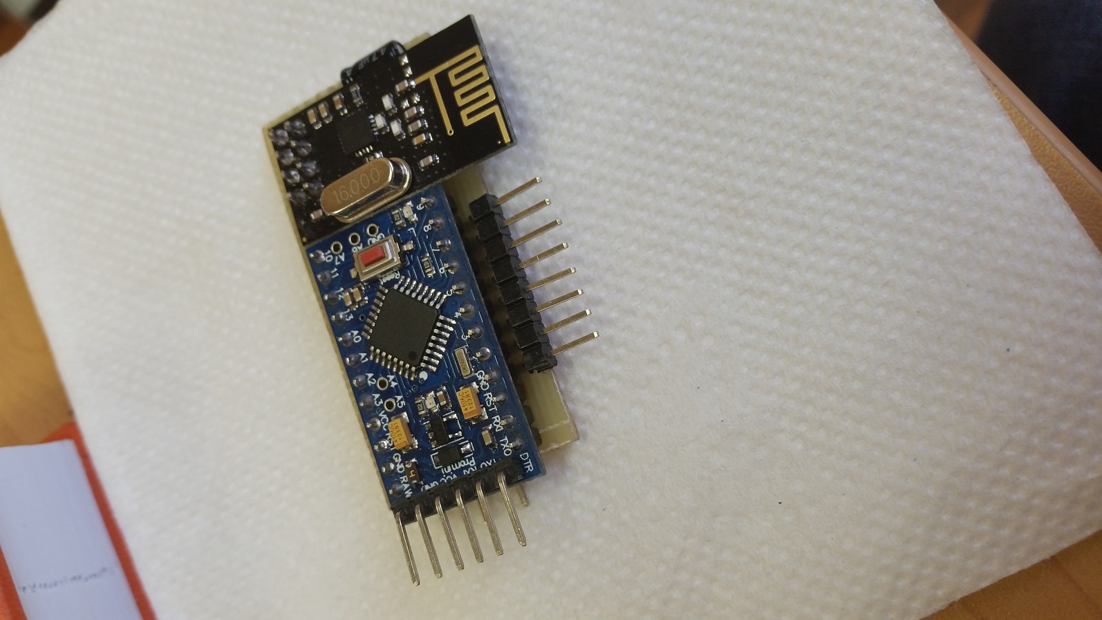
NRF24L01 Radio
Arduino Pro Mini
Push button (6)
Shift Register (SN74HC595)Hello. Help make this project. I need to control 6 groups of 6 through the controller and buttons that are on the device. I neselen writing sketch. what people can help.
needs a sketch and a description of how to collect it. I need to control the lighting in the street like a phone and pressing locally on the device itself.
willing to pay for it, if necessary. -
@vampircik i can help writing a sketch, but what exactly do you want to achieve .
- Just a 6 times on/off button operated relays?
- and why adding the shift register the Pro mini should have enough I/O pins?
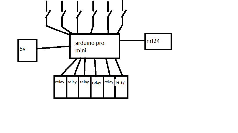
But can you send met the exact wiring diagram, than i can give it a try.
-
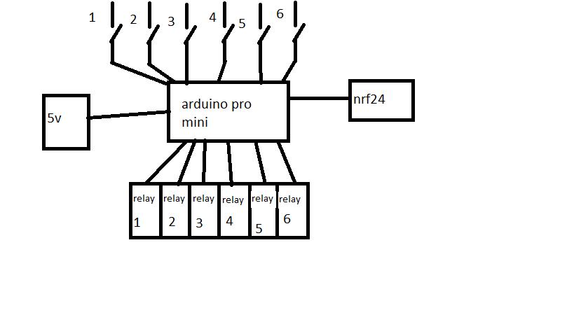
you did not understand. in the scheme will be 6 switches and relays 6. all these controls one Arduino.
@BartE said:
i can help writing a sketch, but what exactly do you want to achieve .
Just a 6 times on/off button operated relays?
and why adding the shift register the Pro mini should have enough I/O pins?
But can you send met the exact wiring diagram, than i can give it a try. -
@vampircik this code snippet should work.
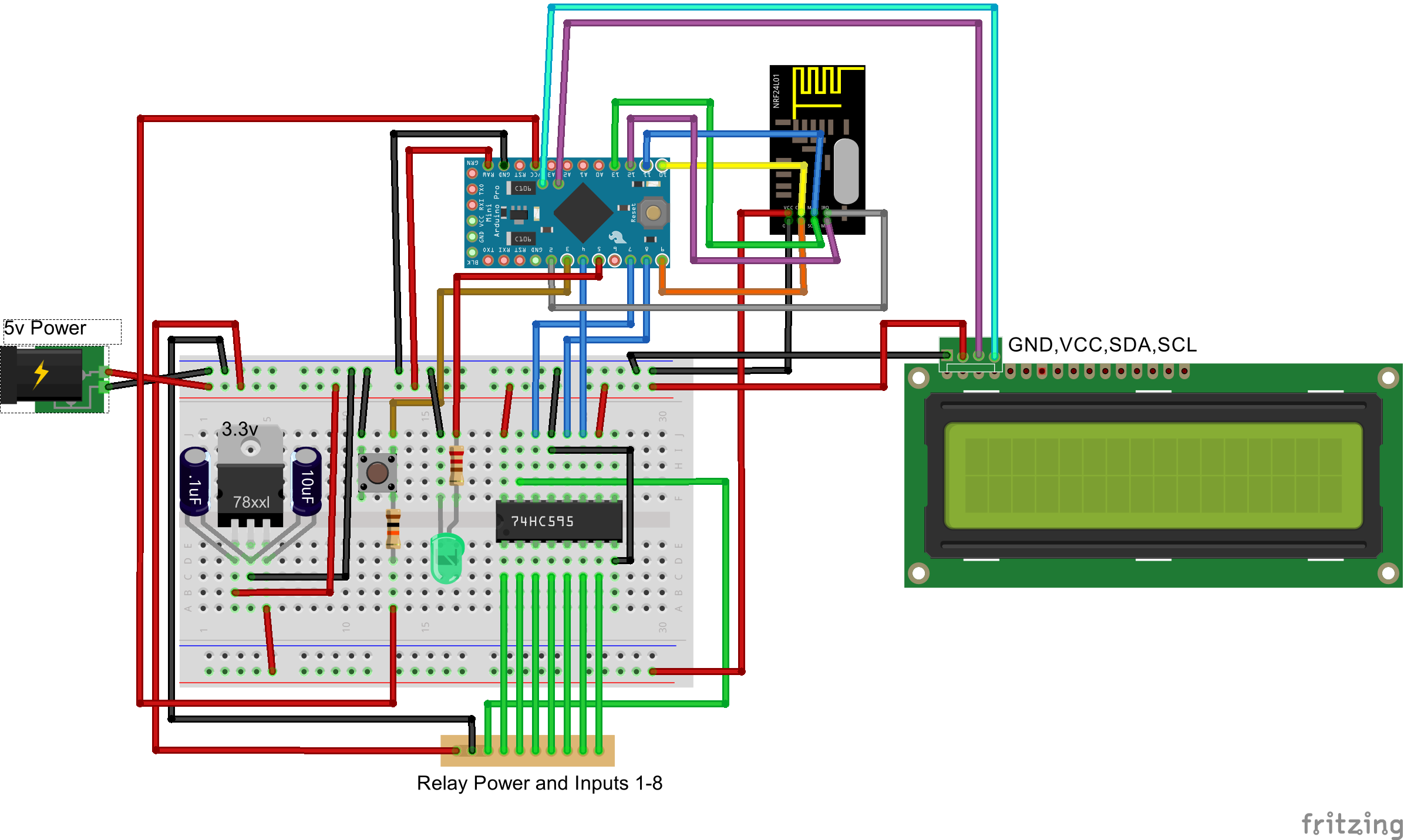
The switch 1 till 6 should be connected to pin A0, A1, A2, A3, 4 and 5 and should connect to ground.
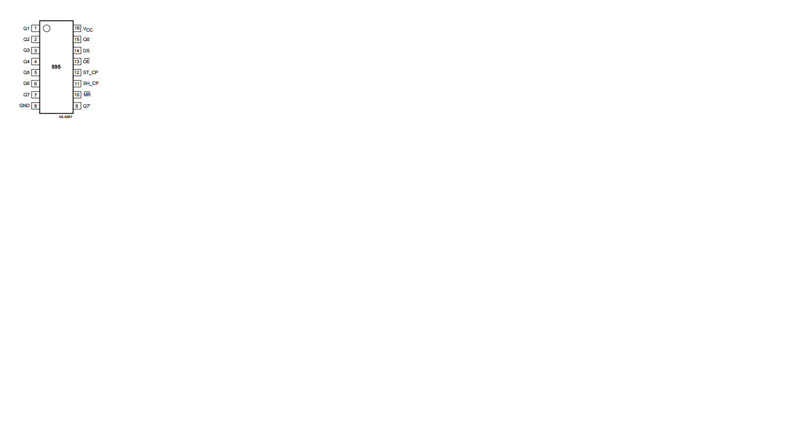
The SN74HC595 should be connected with:
-
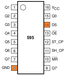
pin 14 (DS) to Arduino pin 6
-
pin 12 (LATCH/ST_CP) to Arduino pin 7
-
pin 8 (CLK/SH_CP) to Arduino pin 11
-
pin 16 (Vcc) and pin 10 (MR) to + 5 volt
-
pin 8 (GND) and pin 13 (OE) to ground
-
relay 1-6 to pin 15 (Q0), 1 (Q1), 2 (Q2), 3 (Q3), 4 (Q4) and 5 (Q4) the other relay pins connected to ground
(note 18/1: fixed pin number error as posted below)
/**
 * The MySensors Arduino library handles the wireless radio link and protocol
 * between your home built sensors/actuators and HA controller of choice.
 * The sensors forms a self healing radio network with optional repeaters. Each
 * repeater and gateway builds a routing tables in EEPROM which keeps track of the
 * network topology allowing messages to be routed to nodes.
 *
 * Created by Henrik Ekblad <henrik.ekblad@mysensors.org>
 * Copyright (C) 2013-2015 Sensnology AB
 * Full contributor list: https://github.com/mysensors/Arduino/graphs/contributors
 *
 * Documentation: http://www.mysensors.org
 * Support Forum: http://forum.mysensors.org
 *
 * This program is free software; you can redistribute it and/or
 * modify it under the terms of the GNU General Public License
 * version 2 as published by the Free Software Foundation.
 *
 *******************************
 *
 * REVISION HISTORY
 * Version 1.0 - Henrik Ekblad
 * Version 1.1 - Bart Eversdijk - 6 switch version with Shift Register (SN74HC595)
 *
 * DESCRIPTION
 * Example sketch showing how to control physical relays.
 * This example will remember relay state after power failure.
 * http://www.mysensors.org/build/relay
 */

#include <MySigningNone.h>
#include <MyTransportNRF24.h>
#include <MyTransportRFM69.h>
#include <MyHwATMega328.h>
#include <MySensor.h>
#include <Bounce2.h>
#include <SPI.h>
#define MYS_INIT_DELAY 500

#define PIN_SR_DATA      6  // shift register data pin   -- data out - 74HC595 (DS) pin 14
#define PIN_SR_LATCH     7  // shift register latch pin  -- data out - 74HC595 (RCLK) pin 12
#define PIN_SR_CLOCK     8  // shift register clock pin  -- data out - 74HC595 (CLK) pin 11

struct SWITCHES {
    byte      currentStatus;
    int       SwitchPin;   // To which Arduino pin this switch is connected
    Bounce    debouncer;
    MyMessage switchMsg;
};

SWITCHES switches[] = {
          {0, A0, Bounce(), MyMessage(0, V_LIGHT)},    // Arduino pin A0
          {0, A1, Bounce(), MyMessage(1, V_LIGHT)},    // Arduino pin A1
          {0, A2, Bounce(), MyMessage(2, V_LIGHT)},    // Arduino pin A2
          {0, A3, Bounce(), MyMessage(3, V_LIGHT)},    // Arduino pin A3
          {0,  4, Bounce(), MyMessage(4, V_LIGHT)},    // Arduino pin D4
          {0,  5, Bounce(), MyMessage(5, V_LIGHT)}     // Arduino pin D5
        };
#define MAXSWITCHES (sizeof(switches)/sizeof(SWITCHES))


// NRFRF24L01 radio driver (set low transmit power by default)
MyTransportNRF24 radio(RF24_CE_PIN, RF24_CS_PIN, RF24_PA_LEVEL_GW);
//MyTransportRFM69 radio;
// Message signing driver (none default)
//MySigningNone signer;
// Select AtMega328 hardware profile
MyHwATMega328 hw;
// Construct MySensors library
MySensor gw(radio, hw);

void setup()
{
    // Initialize library and add callback for incoming messages
    gw.begin(incomingMessage, AUTO, true);

    // Send the sketch version information to the gateway and Controller
    gw.sendSketchInfo("RelaySix", "1.1");

    // Fetch relay status
    for (int id=0; id < MAXSWITCHES; id++) {
       pinMode(switches[id].SwitchPin, INPUT);
       // Activate internal pull-up
       digitalWrite(switches[id].SwitchPin, HIGH);

       gw.present( id, S_LIGHT );
       delay( MYS_INIT_DELAY );

       // Pull the gateway's current dim level - restore light level upon sendor node power-up
       gw.request( id, V_STATUS );
       delay( MYS_INIT_DELAY );

       // After setting up the button, setup debouncer
       switches[id].debouncer.attach(switches[id].SwitchPin);
       switches[id].debouncer.interval(5);
    }

    // Set shift register pins
    pinMode(PIN_SR_DATA,     OUTPUT);
    pinMode(PIN_SR_LATCH,    OUTPUT);
    pinMode(PIN_SR_CLOCK,    OUTPUT);
    digitalWrite(PIN_SR_LATCH, HIGH);

    // Switch off all relays
    sendRelayValues();
}


void loop()
{
    // Alway process incoming messages whenever possible
    gw.process();

    for (byte id = 0; id < MAXSWITCHES; id++) {
        // Button change detected
        if (switches[id].debouncer.update()) {
           Serial.print (F("Switch #"));
           Serial.print (id);
           Serial.print (F(" to "));
           Serial.println (switches[id].debouncer.read());

           // Button release detected toggle relay
           if (!switches[id].debouncer.read()) {
             // Toggle relay status
             switches[id].currentStatus = (switches[id].currentStatus ? 0 : 1);

             // Set the actual relay status (all 6 at once)
             sendRelayValues();

             // Inform the gateway of the current switch status...
             gw.send(switches[id].switchMsg.set(switches[id].currentStatus));
           }
        }
    }
}

void sendRelayValues() {
    // Actually send the valve bits
    digitalWrite(PIN_SR_LATCH, LOW);

    // Shift out all station bit values
    // from the highest bit to the lowest
    for(int id = 0; id < 8; id++)  {
        digitalWrite(PIN_SR_CLOCK, LOW);
        if (id < MAXSWITCHES) {
          digitalWrite(PIN_SR_DATA, (switches[id].currentStatus > 0 ? HIGH : LOW));
        } else {
          digitalWrite(PIN_SR_DATA, LOW);
        }
        digitalWrite(PIN_SR_CLOCK, HIGH);
    }
    // Set new data active
    digitalWrite(PIN_SR_LATCH, HIGH);
}

void incomingMessage(const MyMessage &message) {
  if (message.isAck()) {
     Serial.println("This is an ack from gateway");
  }

  if (message.type == V_LIGHT) {
     byte id = (message.sensor % MAXSWITCHES);

     // Store new value
     switches[id].currentStatus = message.getBool() ? 1 : 0;

     // Set the actual relay status (all 6 at once)
     sendRelayValues();

     // Inform the gateway of the current switch status...
     gw.send(switches[id].switchMsg.set(switches[id].currentStatus));

     // Write some debug info
     Serial.print("Incoming change for sensor:");
     Serial.print(message.sensor);
     Serial.print(", New status: ");
     Serial.println(message.getBool());
   }
}
About your "willing to pay" remark in the original post, just make a donation to the MySensors project
-
-
Maybe it should be like this:
relay 1-6 to pin 15 (Q0), 1 (Q1), 2 (Q2), 3 (Q3), 4 (Q4) and 5 (Q5)
-
@vampircik said:
pin 8 (CLK) to Arduino pin 11
and with the contact what to do?
Looking att the code @BartE posted it seems like it was supposed to be
pin 11 (CLK) to Arduino pin 8