Skip to content
  • MySensors
  • OpenHardware.io
  • Categories
  • Recent
  • Tags
  • Popular
Skins
  • Light
  • Brite
  • Cerulean
  • Cosmo
  • Flatly
  • Journal
  • Litera
  • Lumen
  • Lux
  • Materia
  • Minty
  • Morph
  • Pulse
  • Sandstone
  • Simplex
  • Sketchy
  • Spacelab
  • United
  • Yeti
  • Zephyr
  • Dark
  • Cyborg
  • Darkly
  • Quartz
  • Slate
  • Solar
  • Superhero
  • Vapor

  • Default (No Skin)
  • No Skin
Collapse
Brand Logo
  1. Home
  2. My Project
  3. RelayWithButtonActuator (6 channel)

RelayWithButtonActuator (6 channel)

Scheduled Pinned Locked Moved My Project
33 Posts 3 Posters 15.1k Views 2 Watching
  • Oldest to Newest
  • Newest to Oldest
  • Most Votes
Reply
  • Reply as topic
Log in to reply
This topic has been deleted. Only users with topic management privileges can see it.
  • B Offline
    B Offline
    BartE
    Contest Winner
    wrote on last edited by
    #3

    @vampircik i can help writing a sketch, but what exactly do you want to achieve .

    • Just a 6 times on/off button operated relays?
    • and why adding the shift register the Pro mini should have enough I/O pins?

    But can you send met the exact wiring diagram, than i can give it a try.

    1 Reply Last reply
    0
    • V Offline
      V Offline
      vampircik
      wrote on last edited by
      #4

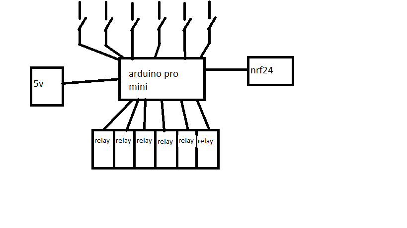
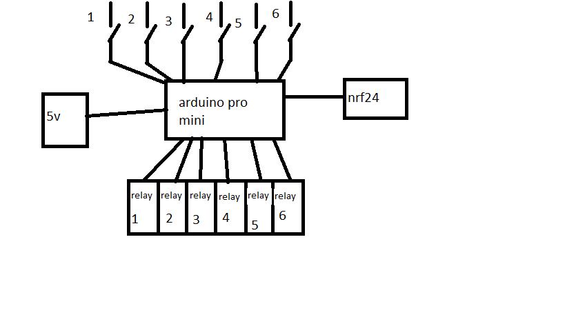
      you did not understand. in the scheme will be 6 switches and relays 6. all these controls one Arduino.

      @BartE said:

      i can help writing a sketch, but what exactly do you want to achieve .

      Just a 6 times on/off button operated relays?
      and why adding the shift register the Pro mini should have enough I/O pins?
      But can you send met the exact wiring diagram, than i can give it a try.

      1 Reply Last reply
      0
      • V Offline
        V Offline
        vampircik
        wrote on last edited by
        #5

        arduino.png

        1 Reply Last reply
        0
        • V Offline
          V Offline
          vampircik
          wrote on last edited by
          #6

          нажали кнопку, включилось реле, потом выключили через телефон это реле. и так в любой последовательности.

          1 Reply Last reply
          0
          • V Offline
            V Offline
            vampircik
            wrote on last edited by
            #7

            arduino.png

            1 Reply Last reply
            0
            • B Offline
              B Offline
              BartE
              Contest Winner
              wrote on last edited by BartE
              #8

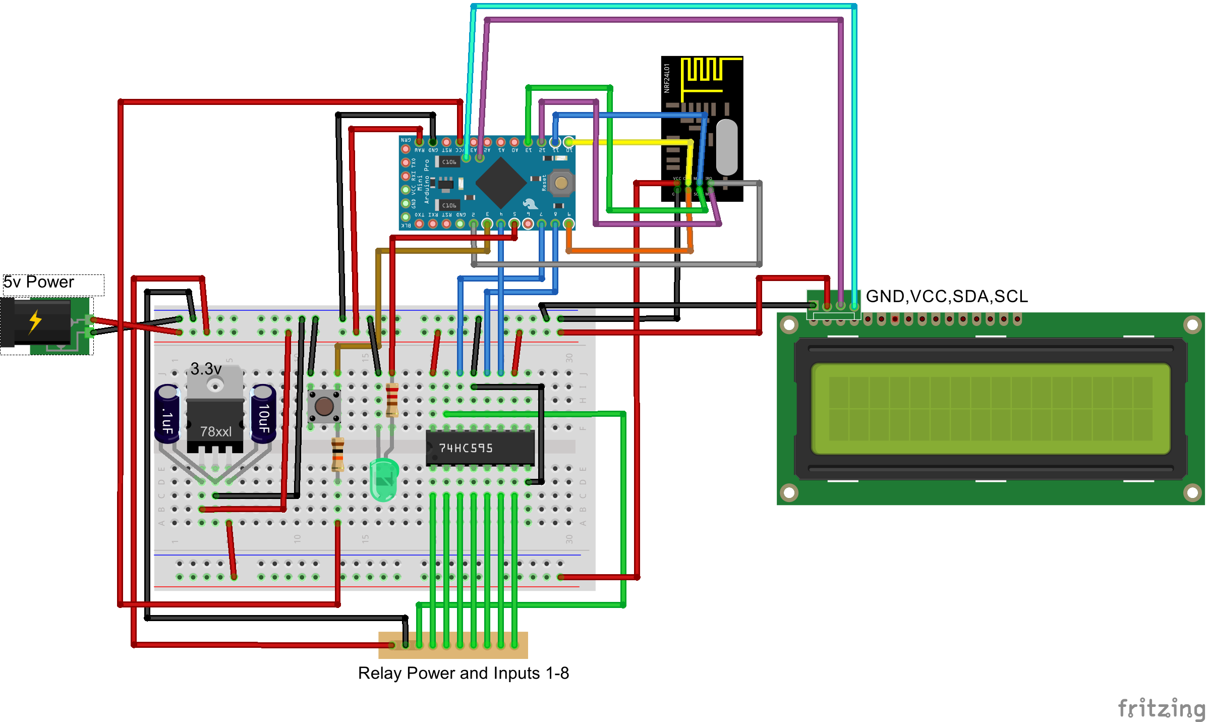
              @vampircik this code snippet should work.

              The switch 1 till 6 should be connected to pin A0, A1, A2, A3, 4 and 5 and should connect to ground.

              The SN74HC595 should be connected with:

              • pin 14 (DS) to Arduino pin 6

              • pin 12 (LATCH/ST_CP) to Arduino pin 7

              • pin 8 (CLK/SH_CP) to Arduino pin 11

              • pin 16 (Vcc) and pin 10 (MR) to + 5 volt

              • pin 8 (GND) and pin 13 (OE) to ground

              • relay 1-6 to pin 15 (Q0), 1 (Q1), 2 (Q2), 3 (Q3), 4 (Q4) and 5 (Q4) the other relay pins connected to ground
                (note 18/1: fixed pin number error as posted below)

              /**
               * The MySensors Arduino library handles the wireless radio link and protocol
               * between your home built sensors/actuators and HA controller of choice.
               * The sensors forms a self healing radio network with optional repeaters. Each
               * repeater and gateway builds a routing tables in EEPROM which keeps track of the
               * network topology allowing messages to be routed to nodes.
               *
               * Created by Henrik Ekblad <henrik.ekblad@mysensors.org>
               * Copyright (C) 2013-2015 Sensnology AB
               * Full contributor list: https://github.com/mysensors/Arduino/graphs/contributors
               *
               * Documentation: http://www.mysensors.org
               * Support Forum: http://forum.mysensors.org
               *
               * This program is free software; you can redistribute it and/or
               * modify it under the terms of the GNU General Public License
               * version 2 as published by the Free Software Foundation.
               *
               *******************************
               *
               * REVISION HISTORY
               * Version 1.0 - Henrik Ekblad
               * Version 1.1 - Bart Eversdijk - 6 switch version with Shift Register (SN74HC595)
               * 
               * DESCRIPTION
               * Example sketch showing how to control physical relays. 
               * This example will remember relay state after power failure.
               * http://www.mysensors.org/build/relay
               */ 
              
              #include <MySigningNone.h>
              #include <MyTransportNRF24.h>
              #include <MyTransportRFM69.h>
              #include <MyHwATMega328.h>
              #include <MySensor.h>
              #include <Bounce2.h>
              #include <SPI.h>
              #define MYS_INIT_DELAY 500
              
              #define PIN_SR_DATA      6  // shift register data pin   -- data out - 74HC595 (DS) pin 14 
              #define PIN_SR_LATCH     7  // shift register latch pin  -- data out - 74HC595 (RCLK) pin 12 
              #define PIN_SR_CLOCK     8  // shift register clock pin  -- data out - 74HC595 (CLK) pin 11
              
              struct SWITCHES {
                  byte      currentStatus; 
                  int       SwitchPin;   // To which Arduino pin this switch is connected
                  Bounce    debouncer;
                  MyMessage switchMsg;
              };
              
              SWITCHES switches[] = {
                        {0, A0, Bounce(), MyMessage(0, V_LIGHT)},    // Arduino pin A0
                        {0, A1, Bounce(), MyMessage(1, V_LIGHT)},    // Arduino pin A1
                        {0, A2, Bounce(), MyMessage(2, V_LIGHT)},    // Arduino pin A2
                        {0, A3, Bounce(), MyMessage(3, V_LIGHT)},    // Arduino pin A3
                        {0,  4, Bounce(), MyMessage(4, V_LIGHT)},    // Arduino pin D4
                        {0,  5, Bounce(), MyMessage(5, V_LIGHT)}     // Arduino pin D5
                      };
              #define MAXSWITCHES (sizeof(switches)/sizeof(SWITCHES))
              
              
              // NRFRF24L01 radio driver (set low transmit power by default) 
              MyTransportNRF24 radio(RF24_CE_PIN, RF24_CS_PIN, RF24_PA_LEVEL_GW);  
              //MyTransportRFM69 radio;
              // Message signing driver (none default)
              //MySigningNone signer;
              // Select AtMega328 hardware profile
              MyHwATMega328 hw;
              // Construct MySensors library
              MySensor gw(radio, hw);
              
              void setup()  
              {   
                  // Initialize library and add callback for incoming messages
                  gw.begin(incomingMessage, AUTO, true);
                  
                  // Send the sketch version information to the gateway and Controller
                  gw.sendSketchInfo("RelaySix", "1.1");
              
                  // Fetch relay status
                  for (int id=0; id < MAXSWITCHES; id++) {
                     pinMode(switches[id].SwitchPin, INPUT);
                     // Activate internal pull-up
                     digitalWrite(switches[id].SwitchPin, HIGH); 
                      
                     gw.present( id, S_LIGHT );
                     delay( MYS_INIT_DELAY );
              
                     // Pull the gateway's current dim level - restore light level upon sendor node power-up
                     gw.request( id, V_STATUS );
                     delay( MYS_INIT_DELAY );
                     
                     // After setting up the button, setup debouncer
                     switches[id].debouncer.attach(switches[id].SwitchPin);
                     switches[id].debouncer.interval(5);
                  }
                  
                  // Set shift register pins
                  pinMode(PIN_SR_DATA,     OUTPUT);
                  pinMode(PIN_SR_LATCH,    OUTPUT);
                  pinMode(PIN_SR_CLOCK,    OUTPUT);
                  digitalWrite(PIN_SR_LATCH, HIGH);
                  
                  // Switch off all relays
                  sendRelayValues();
              }
              
              
              void loop() 
              {
                  // Alway process incoming messages whenever possible
                  gw.process();
                
                  for (byte id = 0; id < MAXSWITCHES; id++) {
                      // Button change detected
                      if (switches[id].debouncer.update()) {
                         Serial.print (F("Switch #"));
                         Serial.print (id);
                         Serial.print (F(" to "));
                         Serial.println (switches[id].debouncer.read());
                         
                         // Button release detected toggle relay
                         if (!switches[id].debouncer.read()) {
                           // Toggle relay status
                           switches[id].currentStatus = (switches[id].currentStatus ? 0 : 1);
                           
                           // Set the actual relay status (all 6 at once)
                           sendRelayValues();
                           
                           // Inform the gateway of the current switch status...
                           gw.send(switches[id].switchMsg.set(switches[id].currentStatus));
                         }
                      }
                  }
              }
              
              void sendRelayValues() {
                  // Actually send the valve bits
                  digitalWrite(PIN_SR_LATCH, LOW);
              
                  // Shift out all station bit values
                  // from the highest bit to the lowest
                  for(int id = 0; id < 8; id++)  {
                      digitalWrite(PIN_SR_CLOCK, LOW);
                      if (id < MAXSWITCHES) {
                        digitalWrite(PIN_SR_DATA, (switches[id].currentStatus > 0 ? HIGH : LOW));
                      } else {
                        digitalWrite(PIN_SR_DATA, LOW);
                      }
                      digitalWrite(PIN_SR_CLOCK, HIGH);          
                  }
                  // Set new data active
                  digitalWrite(PIN_SR_LATCH, HIGH);
              }
              
              void incomingMessage(const MyMessage &message) {
                if (message.isAck()) {
                   Serial.println("This is an ack from gateway");
                }
                
                if (message.type == V_LIGHT) {
                   byte id = (message.sensor % MAXSWITCHES);
              
                   // Store new value
                   switches[id].currentStatus = message.getBool() ? 1 : 0;
                   
                   // Set the actual relay status (all 6 at once)
                   sendRelayValues();
                   
                   // Inform the gateway of the current switch status...
                   gw.send(switches[id].switchMsg.set(switches[id].currentStatus));
                         
                   // Write some debug info
                   Serial.print("Incoming change for sensor:");
                   Serial.print(message.sensor);
                   Serial.print(", New status: ");
                   Serial.println(message.getBool());
                 } 
              }


              About your "willing to pay" remark in the original post, just make a donation to the MySensors project

              1 Reply Last reply
              0
              • V Offline
                V Offline
                vampircik
                wrote on last edited by
                #9

                Thank you. Today I will try. according to the results let you know.

                1 Reply Last reply
                0
                • V Offline
                  V Offline
                  vampircik
                  wrote on last edited by
                  #10

                  @BartE said:

                  pin 8 (CLK) to Arduino pin 11

                  pin 16 (Vcc) to + 5 volt

                  pin 8 (GND) to ground

                  ?
                  Arduino pin 11 = (GND) ?

                  1 Reply Last reply
                  0
                  • V Offline
                    V Offline
                    vampircik
                    wrote on last edited by
                    #11

                    pin 8 (CLK) to Arduino pin 11
                    pin 8 (GND) to ground

                    contrary

                    1 Reply Last reply
                    0
                    • V Offline
                      V Offline
                      vampircik
                      wrote on last edited by
                      #12

                      pin 14 (DS) to Arduino pin 6

                      relay 1-6 to pin 14 (Qa)

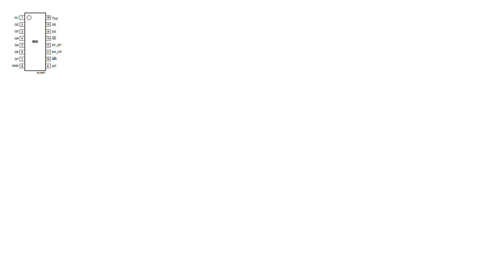
                      contraryмикросхема.png

                      1 Reply Last reply
                      0
                      • V Offline
                        V Offline
                        vampircik
                        wrote on last edited by
                        #13
                        This post is deleted!
                        1 Reply Last reply
                        0
                        • V Offline
                          V Offline
                          vampircik
                          wrote on last edited by
                          #14

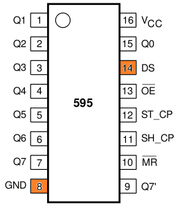
                          pin 14 (DS) to Arduino pin 6
                          pin 8 (CLK) to Arduino pin 11
                          pin 8 (GND) to ground
                          relay 1-6 to pin 14 (Qa),
                          микрик.png

                          1 Reply Last reply
                          0
                          • K Offline
                            K Offline
                            korttoma
                            Hero Member
                            wrote on last edited by
                            #15

                            Maybe it should be like this:

                            relay 1-6 to pin 15 (Q0), 1 (Q1), 2 (Q2), 3 (Q3), 4 (Q4) and 5 (Q5)

                            • Tomas
                            1 Reply Last reply
                            0
                            • V Offline
                              V Offline
                              vampircik
                              wrote on last edited by
                              #16

                              pin 8 (CLK) to Arduino pin 11

                              and with the contact what to do?

                              K 1 Reply Last reply
                              0
                              • V Offline
                                V Offline
                                vampircik
                                wrote on last edited by
                                #17

                                Arduino pin 11 = MOSI NRF24

                                1 Reply Last reply
                                0
                                • V Offline
                                  V Offline
                                  vampircik
                                  wrote on last edited by
                                  #18

                                  wiring.png
                                  it seems to me must be so connected. except for the screen?

                                  1 Reply Last reply
                                  0
                                  • V vampircik

                                    pin 8 (CLK) to Arduino pin 11

                                    and with the contact what to do?

                                    K Offline
                                    K Offline
                                    korttoma
                                    Hero Member
                                    wrote on last edited by
                                    #19

                                    @vampircik said:

                                    pin 8 (CLK) to Arduino pin 11

                                    and with the contact what to do?

                                    Looking att the code @BartE posted it seems like it was supposed to be

                                    pin 11 (CLK) to Arduino pin 8

                                    • Tomas
                                    1 Reply Last reply
                                    0
                                    • V Offline
                                      V Offline
                                      vampircik
                                      wrote on last edited by
                                      #20

                                      ok try. ...............

                                      1 Reply Last reply
                                      0
                                      • K Offline
                                        K Offline
                                        korttoma
                                        Hero Member
                                        wrote on last edited by
                                        #21

                                        So the correct instructions should have been:

                                        pin 14 (DS) to Arduino pin 6
                                        pin 12 (RCLK) to Arduino pin 7
                                        pin 11 (CLK) to Arduino pin 8
                                        pin 16 (Vcc) to + 5 volt
                                        pin 8 (GND) to ground

                                        relay 1-6 to pin 15 (Q0), 1 (Q1), 2 (Q2), 3 (Q3), 4 (Q4) and 5 (Q5) the other relay pins connected to ground

                                        Please @BartE correct me if I'm wrong since I have no personal experience from this kind of setup.

                                        • Tomas
                                        1 Reply Last reply
                                        0
                                        • V Offline
                                          V Offline
                                          vampircik
                                          wrote on last edited by
                                          #22

                                          collected is not working. the controller displays the switch, but it does not control the Arduino.

                                          1 Reply Last reply
                                          0

                                          Hello! It looks like you're interested in this conversation, but you don't have an account yet.

                                          Getting fed up of having to scroll through the same posts each visit? When you register for an account, you'll always come back to exactly where you were before, and choose to be notified of new replies (either via email, or push notification). You'll also be able to save bookmarks and upvote posts to show your appreciation to other community members.

                                          With your input, this post could be even better 💗

                                          Register Login
                                          Reply
                                          • Reply as topic
                                          Log in to reply
                                          • Oldest to Newest
                                          • Newest to Oldest
                                          • Most Votes


                                          23

                                          Online

                                          12.0k

                                          Users

                                          11.2k

                                          Topics

                                          113.4k

                                          Posts


                                          Copyright 2025 TBD   |   Forum Guidelines   |   Privacy Policy   |   Terms of Service
                                          • Login

                                          • Don't have an account? Register

                                          • Login or register to search.
                                          • First post
                                            Last post
                                          0
                                          • MySensors
                                          • OpenHardware.io
                                          • Categories
                                          • Recent
                                          • Tags
                                          • Popular