Simple Temp/Light/Time setup with LCD 1.4 (no beta anymore)
-
Have a simple setup with a standard hitachi 16x2 display showing temperature, light level and current server time and connection status. Not done yet because i want it to show current scene for the location where this setup is add. But scenes are not supported yet.
The setup is using the 1.4 beta library setup.
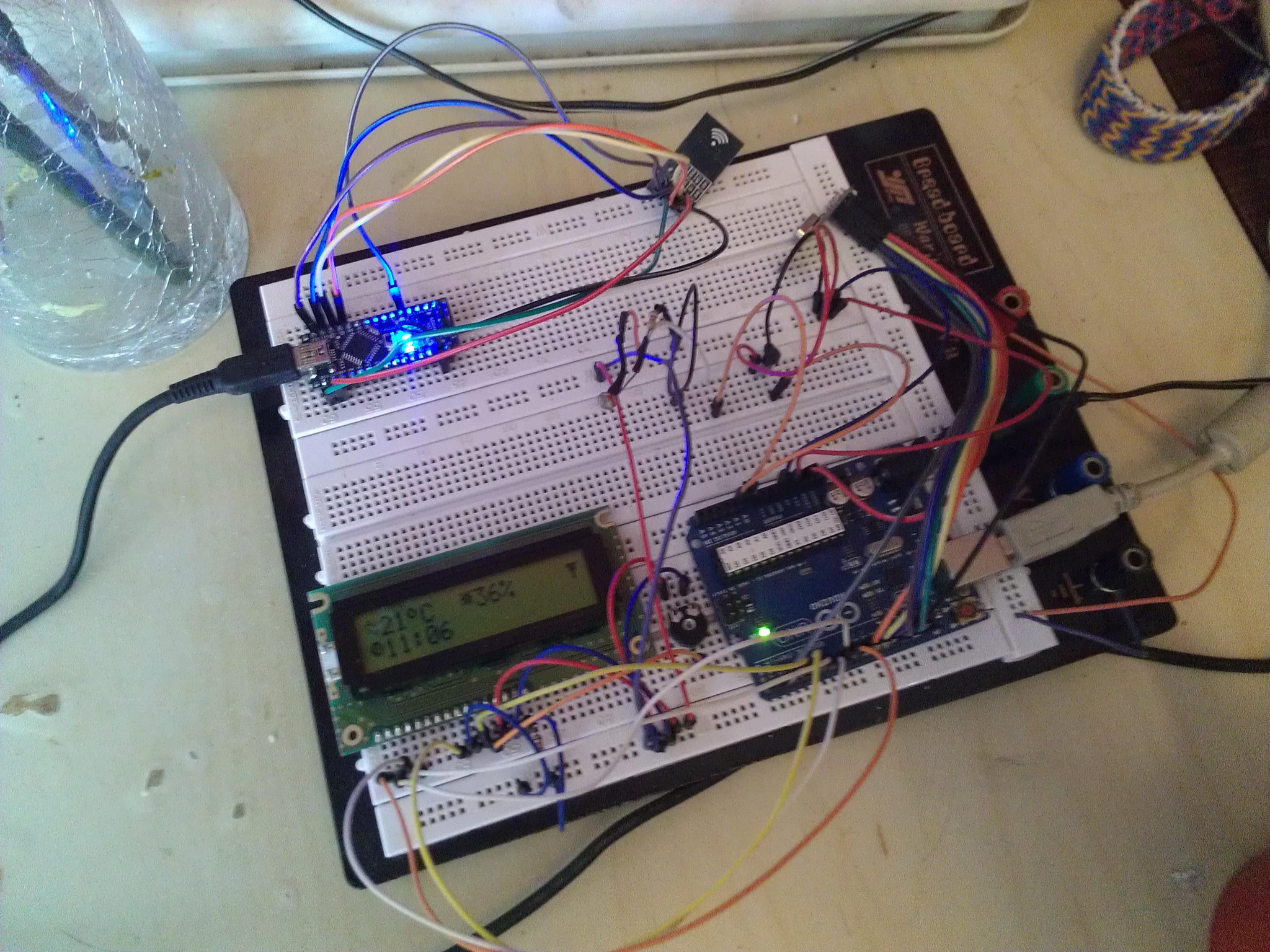
The temperature and the light values are updated every ten seconds (approximately) and values are send to the server about every 59 seconds. Also every minute the time is updated by using the time request method and displays the time in current timezone and correct offset (daylight savings). It can be +59 or -59 seconds off because the server does not yet pushes the time on change and is set on request
.
On the display at the right top is a an antenna character which will blink of no data is received from the server. This is used in combination with the time request if there is no response within 3 seconds (quite a very large margin) the antenna will blink saying there is no server response. When the server responses again it will stop blinking. I on purpose set it on server responses and not at radio level, because both mean no server "connection" (interaction). -
Nice work!
Would you mind sharing the sketch file for this sensor node? I would like to do something similar but I'm not skilled enough to start from scratch. -
@korttoma
Sure:This is the current sketch, it is not final yet, so improvements are not put in it yet and not all the doc comments.
#include <TimedAction.h>
#include <SPI.h>
#include <MySensor.h>
#include <LiquidCrystal.h>
#include <Time.h>

/*
 * The LCD circuit:
 * LCD RS pin to digital pin 8
 * LCD Enable pin to digital pin 7
 * LCD D4 pin to digital pin 6
 * LCD D5 pin to digital pin 5
 * LCD D6 pin to digital pin 4
 * LCD D7 pin to digital pin 3
 * LCD R/W pin to ground
 * The used  LCD is an PC1602-F Be aware that the pins 15 and 16 are next to pin one so from
 * Left to right viewed from on top (facing lcd screen) it is 14, 13, 12, 11, 10, 9, 8, 7, 6, 5, 4, 3, 2, 1, 16, 15
*/

#define CHILD_ID_LIGHT 0
#define CHILD_ID_TMP   1
#define LIGHT_SENSOR_ANALOG_PIN 0
#define TMP_SENSOR_ANALOG_PIN   1

unsigned long SLEEP_TIME = 94; // Sleep time between reads (in milliseconds) (We do calculations and wait 5 ms between readings)
int readingscounter      = 0;

int timeCheckCounter     = 0;
boolean netAvailSwap     = false;

MySensor gw;
MyMessage msgLight(CHILD_ID_LIGHT, V_LIGHT_LEVEL);
MyMessage msgTemp (CHILD_ID_LIGHT, V_TEMP);
uint16_t luxTotal;
uint16_t tmpTotal;

byte temp[8] = {
  0b01000,
  0b10101,
  0b00010,
  0b01000,
  0b10101,
  0b00010,
  0b00000,
  0b00000
};

byte degree[8] = {
  0b01100,
  0b10010,
  0b10010,
  0b01100,
  0b00000,
  0b00000,
  0b00000,
  0b00000
};

byte sun[8] = {
  0b10101,
  0b01110,
  0b11011,
  0b01110,
  0b10101,
  0b00000,
  0b00000,
  0b00000
};

byte antennaOk[8] = {
  0b11111,
  0b01110,
  0b01110,
  0b00100,
  0b00100,
  0b00100,
  0b00000,
  0b00000
};

byte timeSymbol[8] = {
  0b01110,
  0b10101,
  0b10101,
  0b11001,
  0b01110,
  0b00000,
  0b00000,
  0b00000
};

LiquidCrystal lcd(3, 4, 5, 6, 7, 8);

TimedAction timedAction = TimedAction(1000,updateSensors);

void setup() {

  lcd.begin(16, 2);
  lcd.createChar(0, degree);
  lcd.createChar(1, sun);
  lcd.createChar(3, antennaOk);
  lcd.createChar(4, temp);
  lcd.createChar(5, timeSymbol);
  // Send the sketch version information to the gateway and Controller
  lcd.setCursor(0, 0);
  lcd.print("User status");
  lcd.setCursor(0, 1);
  lcd.print("PiDome");

  // Register all sensors to gateway (they will be created as child devices)
  gw.begin();
  gw.sendSketchInfo("PiDome u-stat+lcd", "1.0");
  gw.present(CHILD_ID_LIGHT, S_LIGHT_LEVEL);
  gw.present(CHILD_ID_TMP, S_TEMP);
  delay(3000);
  gw.requestTime(receiveTime);
}


void loop(){
  gw.process();
  timedAction.check();
}

void updateSensors(){
  int curLux = constrain(map(analogRead(LIGHT_SENSOR_ANALOG_PIN), 0, 1023, 0, 101),0,100);
  luxTotal = luxTotal + curLux;
  delay(1);
  analogRead(TMP_SENSOR_ANALOG_PIN);///first read can be off because we just read the light sensor, so do a read and discard it
  int curTemp = (((analogRead(TMP_SENSOR_ANALOG_PIN) * 5.0) / 1024) - 0.5) * 100;
  tmpTotal = tmpTotal + curTemp;
  if(readingscounter==10){ lcd.setCursor(0, 0); lcd.print("               ");lcd.setCursor(0, 0);lcd.write(byte(4));lcd.print(curTemp);lcd.write(byte(0));lcd.print("C  ");lcd.write(byte(1));lcd.print(curLux);lcd.print("%"); }
  if(timeCheckCounter==62){
    lcd.setCursor(15,0);
    (netAvailSwap==true)?lcd.write(byte(3)):lcd.print(" ");
    netAvailSwap=!netAvailSwap;
  } else {
    lcd.setCursor(15,0);
    if(netAvailSwap==false){ lcd.write(byte(3)); }
    netAvailSwap = true;
  }
  if(readingscounter==59){
    gw.send(msgLight.set(luxTotal/readingscounter));
    gw.send(msgTemp.set(tmpTotal/readingscounter));
    readingscounter = 1;
    tmpTotal = 0;
    luxTotal = 0;
    gw.requestTime(receiveTime);
  } else {
    readingscounter++;
    if(timeCheckCounter!=62)timeCheckCounter++;
  }
}

void receiveTime(unsigned long time) {
  timeCheckCounter = 0;
  netAvailSwap = true;
  setTime(time);
  lcd.setCursor(0,1);
  lcd.write(byte(5));
  lcdDigits(hour());
  lcd.print(":");
  lcdDigits(minute());
}

void lcdDigits(int digits){
  if(digits < 10)
    lcd.print('0');
  lcd.print(digits);
}
TimedAction is from the Arduino playground (I quickly needed something to do timed actions).
-
Thanks for the sketch @JOHN
It gives me a few ideas how to set things up but it seems like you are using a different lcd library then I had in mind.
That one use way to many digital pins for my taste.
I was planing on using the LiquidCrystal_I2C.h once my ordered display gets here.Thanks again ;)
-
Thanks for the sketch @JOHN
It gives me a few ideas how to set things up but it seems like you are using a different lcd library then I had in mind.
That one use way to many digital pins for my taste.
I was planing on using the LiquidCrystal_I2C.h once my ordered display gets here.Thanks again ;)
-
I found my LCD in the mailbox just now. Time pull something together.
-
@korttoma Succes!
I've made a couple of small changes:
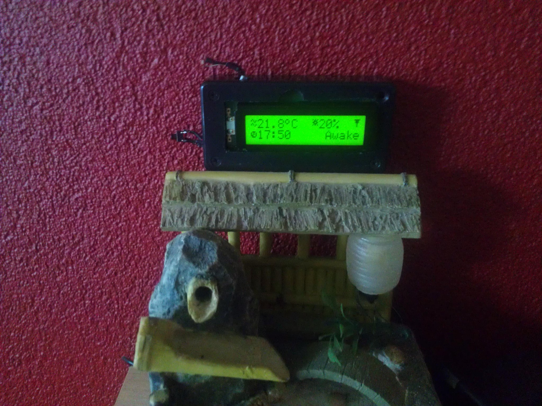
Having a NPN laying around the display's back-light is now handled by the Atmega. And the display now shows overall users status (Awake/Sleeping/Away).
The display turns on when the users status change, when a button is pressed or connection is "lost" (No server response). After 20 seconds of user change/button press/"connection" back the display's back-light goes off again.Planning: An extra button to send a signal to the server where it toggles user status to sleep/awake (all lights off etc.../morning routines) depending on time settings on the server.
That leaves one pin unused. Any idea's?
-
A little update:
The below setup will run for a while until i have founded some suited casing for it... It has the same functionalities as above but in the end will get more buttons via a binary encoder i have laying around. So, it now is soldered and put in a case used in an other project (explains the BIG cutout where the LCD is seen. At the top the LDR, an the left a tactile used for the display backlight, and at the bottom (not seen) is a tmp36 sticking out.
-
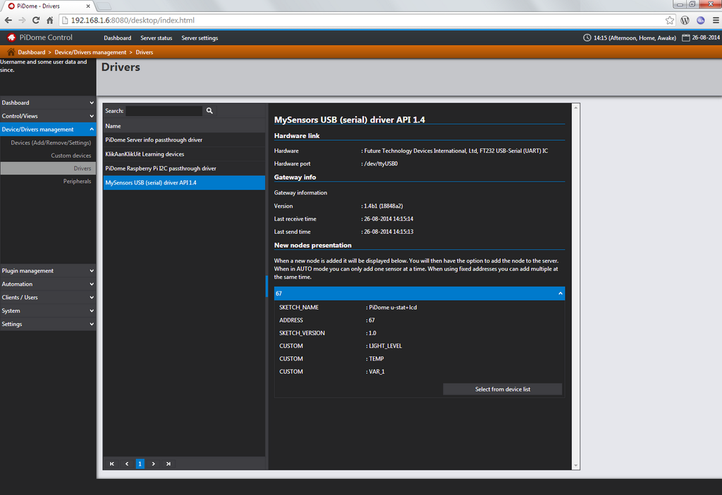
I'm also busy with mysensors integration in the server i'm creating... below is a work in progress screenshot of a mysensors device to be added. All though it is shown in the screenshot, automatic node addressing is not yet supported. Also automatic device creation is not done yet, you will need first to define the device yourself (fields etc..).
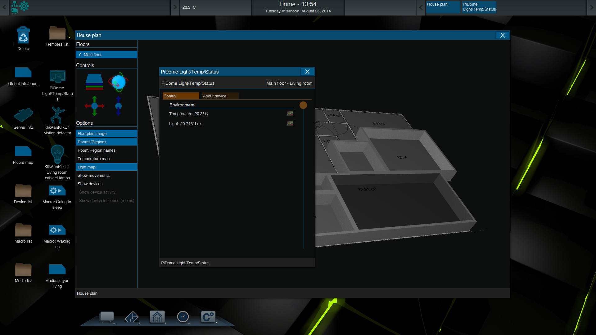
I'm also working on a desktop and mobile client.. This is how it looks in the desktop client when this specific device is added to the server and assigned to the floor planner with light intensity (LUX) enabled. Currently i only have one device active with lux (which is the device on this page).
I hope to get full mysensors implementation soon done, i will also include mysensor example devices to the mysensor device declarations.
-
@hek
Yeah sure no problem, all though there is an extra button upcoming in the next couple of days(/week?) which will say something like "Auto create device" where the driver then will be able to create the needed xml for the shown device. I'm extremely busy at the moment need to prepare for a hell lot of things the upcoming weeks so there is no real ETA for that button yet.Maybe it is handy to put an extra screenshot on how it looks when you add the serial gateway for the first time (page auto refreshes when an usb device is plugged in):

-
I have updated the support this evening and the implementation now also shows the last 20 messages being requested to be logged by the gateway.

Also i have added the possibility to auto assign node ID's but can not test it because the project i started this post with is running live with a server instance and is used in triggers which control my lighting... Current method is to turn on a sensor node, take a look at the last 20 messages (refresh the page by clicking on the MySensors driver). If the log shows an address is assigned, restart the sensor node.
Automatic creation of devices is put on hold because of thread: http://forum.mysensors.org/topic/304/unit-standardization-1-4 so devices still need to be created by hand.
[EDIT]
Maybe handy to create a different post about the mysensors support if that is allowed of course
[/EDIT] -
I have added a device editor to the server. It uses the sensor types as a group and the sensor variable as the control.
Group (sensor):

Control (sensor variable):

This will be my last post here because my controller has got it's own controller page :)
Hello! It looks like you're interested in this conversation, but you don't have an account yet.
Getting fed up of having to scroll through the same posts each visit? When you register for an account, you'll always come back to exactly where you were before, and choose to be notified of new replies (either via email, or push notification). You'll also be able to save bookmarks and upvote posts to show your appreciation to other community members.
With your input, this post could be even better 💗
Register Login