PIR am312
-
how about the lens? Did you make a case for it?
I will test using lens from AM312 & from SR501 (made the space and holes for that on the PCB). I have ordered some other ones from AliExpress, too.
No case yet as I just spent a lot of nearly sleepless nights finishing a lot of PCBs. Now time for code preparation before I receive the boards, then 3D design and tests while the 3D printer is printing :)I really like your PCB layouts. Is that Eagle, or some other package that you're using? I'm using Diptrace, which meets my needs and was easy to learn, but your package looks like it's more polished and easier to see both sides of the board at the same time.
-
I really like your PCB layouts. Is that Eagle, or some other package that you're using? I'm using Diptrace, which meets my needs and was easy to learn, but your package looks like it's more polished and easier to see both sides of the board at the same time.
I really like your PCB layouts. Is that Eagle, or some other package that you're using? I'm using Diptrace, which meets my needs and was easy to learn, but your package looks like it's more polished and easier to see both sides of the board at the same time.
Yes that's eagle, found it pretty easy to learn also.
But I made my last PCBs with it this week I think, I will switch to KiCad to avoid the annoying limitations in Eagle. It will be a pain to learn everything again, but at least I won't miss the autorouter as I love routing :D -
-
@AWI Thank you for your photo. Without it, I'm not sure how I would have deduced the correct pinout.
So far I've only powered it up--and with merely a DMM attached to the output pin--but as a quick test it seems to work.
-
@AWI Thank you for your photo. Without it, I'm not sure how I would have deduced the correct pinout.
There are some tiny '+' and '-' signs on the breakout board near the pins but they are barely visible.
On mine I don't see any pinout markings at all.
I used a uCurrent Gold to measure the current, and and at 3.3v my measurements came out at 13.1ua in standby mode and 14.3ua at "motion detected" mode. I haven't tested it for false positives yet (it may take a while to gather the data on that), but so far I'm impressed. Nice find!
-
So, I made a little test jig to try it out. It seems to have roughly 4 detection "zones" with fairly wide gaps between them where it's more or less blind. Also, if I walk straight at it from the front, it doesn't detect me until I'm about 3 feet away. So, although I'm no expert, I'd say the detection coverage is kinda spotty. Maybe the small domed plastic optics are sub-optimal? Has anyone tried alternatives?
Just thinking out loud, but maybe you can use two and by skewing their alignment try to make it so that the gaps in one are mostly covered by the detection zones of the other, and visa versa?
Not sure how to make the best use of this yet, but I do like the very low power consumption. I think there's a pony in there somewhere, and we just need to find it.
Anyone have ideas?
-
Did that resonate with anyone? Has anyone else observed "the problem" I described? If not, maybe I set it up wrong.
-
I have experienced similar behavior yes, didn't have time to check enough but from some directions it gave me the impression not to detect anything.
It seemed better with lens from a SR501. I'm waiting for the PCB with am612 to be able to test with a properly aligned SR501 lens. -
I have experienced similar behavior yes, didn't have time to check enough but from some directions it gave me the impression not to detect anything.
It seemed better with lens from a SR501. I'm waiting for the PCB with am612 to be able to test with a properly aligned SR501 lens.@Nca78
Thanks! I just now took the lens cover off an SR501 and very crudely attached it to the Banggood sensor (after first removing its cap). It seems to be an improvement. So, I expect doing a proper job of it will yield an even greater improvement.Fortunately, it looks as though there's a good variety of PIR lenses on Aliexpress for cheap.
-
the fun will be to make them fit on the sensor :)
I was thinking hot glue and a cardboard backing for prototyping, but maybe a backing which actually reflects IR (like a metal foil?) would help keep the IR bouncing around inside it more and be a good thing. Really not sure.
On the other hand, maybe there's a better lens which can snap onto the existing body. That would be better, at least from a hassle standpoint.
-
maybe make a mock pcb board of a SR501 with a hole in the middle so you can attach the lens on the board and stick the am312 in the center hole
maybe make a mock pcb board of a SR501 with a hole in the middle so you can attach the lens on the board and stick the am312 in the center hole
Or, as a POC, just drill a hole in the middle of an SR501 board, since the lens already snaps smartly to that board.
Does PCB need a special kind of drill bit, like for glass or something?
-
So I guess this may mean we won't be using the bangood sensors after all. Instead we'll be buying chips and mounting them to custom PCB's, like NCA78 is doing. That is, unless there's a better lens cap that just naturally fits the body of the banggood sensor.
Which means I should order some of those PIR sensor IC's soon, given the long shipping lead times.
-
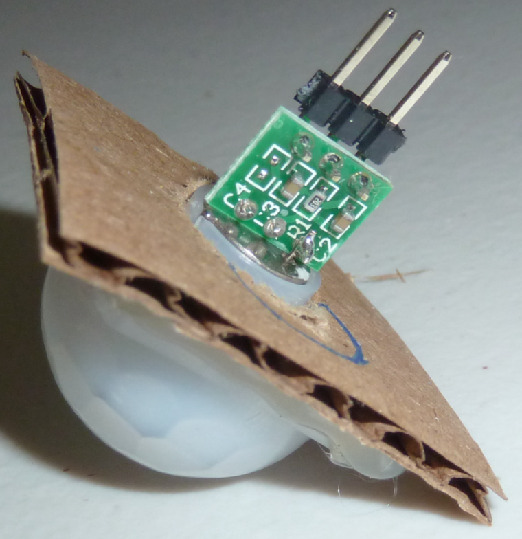
For a preliminary POC, I made a lens holder with cardboard and hot glue:
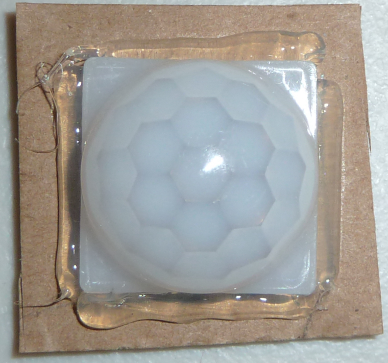
and drilled a 15/32" hole in the middle for the PIR element, which I shoved in the back:
Obviously it's still crude, but it's better than my first attempt. It also performs better. It still has spotty coverage, but not as bad as before. Obviously a more properly installed and aligned lens should perform better still.
Anyhow, that's as far as I'm going to take it for now. I look forward to hearing what others might come up with, as well as their impressions about the coverage.
-
I did. What you see is just the holder that the regular lens snaps onto.