💬 AC-DC double solid state relay module
-
Hi,
can we install this module in a wall ?
Can we command shutters ?
Thx -
I updated source file for this module, so it supports MySensors 2.0 now and sends temperature data too. You can pick it at my github page. Total size for 'Arduino Pro or Pro Mini w/ ATmega328 (5V, 16 MHz)'
Program size: 13 396 bytes (used 44% of a 30 720 byte maximum) (2,78 secs)
Minimum Memory Usage: 614 bytes (30% of a 2048 byte maximum) -
Hi,
can we install this module in a wall ?
Can we command shutters ?
Thx@tonnerre33 said:
Hi,
can we install this module in a wall ?
Can we command shutters ?For the wall, that's the idea of keeping the 50*50mm size :)
For the shutters technically yes, but there are (at least) 2 problems :- if you have the 2 relays on at the same time = 2 directions you will probably kill the motor, there is no hardware protection on this board to avoid that (one of the relays must have power only when the other one is in off state). This can be done in software so it's not blocking.
- if you want to be able to control the level/percentage of closing, you need to measure time from min to max position, to do that you need to measure current (when motor stop consuming current it means shutter has reached it's 0% or 100% position). But there is no current sensor on this board, so you either need to implement a manual calibration process (that will lose precision over time) or use only manual control.
I am planning to test it when I have some time, and when I receive the PCB.
-
Hi Approx
Thanks for the effort here. I have all the bits except for the PCBs which were shipped a week ago so not far off. -
@dpressle my experience shows, that this PCB works fine with LE33 when powered from mains, however nrf fails to receive data, when powered from FTDI through arduino.
-
@Konstantin-Kolesnichenko what voltage is selected on the ftdi adapter ? If it's 3.3V it's not surprising as the LE33 needs over 3.5V (3.3V + 0.2V voltage drop).
-
@okos said:
Hello, i have question can i use arduino pro mini 3.3 V?
http://s.aliexpress.com/zmyyY7BV
Thanx
I will try to use one and HLK-PM03 generating 3.3V, and bypassing the regulator on the PCB.
The only question is about the SSR relays, they are supposed to work with 5V logic levels, I need to test the relays I have received work reliably with 3.3V logic.
Datasheet says operating range is 4-6V but 4V is the maximum value at which they should switch on, so there's some hope here ;) -
@tonnerre33 said:
Hi,
can we install this module in a wall ?
Can we command shutters ?For the wall, that's the idea of keeping the 50*50mm size :)
For the shutters technically yes, but there are (at least) 2 problems :- if you have the 2 relays on at the same time = 2 directions you will probably kill the motor, there is no hardware protection on this board to avoid that (one of the relays must have power only when the other one is in off state). This can be done in software so it's not blocking.
- if you want to be able to control the level/percentage of closing, you need to measure time from min to max position, to do that you need to measure current (when motor stop consuming current it means shutter has reached it's 0% or 100% position). But there is no current sensor on this board, so you either need to implement a manual calibration process (that will lose precision over time) or use only manual control.
I am planning to test it when I have some time, and when I receive the PCB.
@Nca78 thanx for your answer ;)
You are right, 2 directions can kill the motor that's why we need one relay for on/off the motor and the other for command up/down.
But for command up/down, and in order to do an hardware protection, we can use an inversor relay.
Do you know an inversor relay with the same size ? I didn't find that kind of relay :( -
@tonnerre33
I have made a board for tshutters ;)
on my side, it's completed. I'm actually checking files, writing docs for my git (bom etc..) I have so much projects almost completed to show so I have to clean my projects one by one :persevere: and I don't talk about software stuff too..arghh!
Here it is https://forum.mysensors.org/topic/2944/roller-shutter-node -
Yes, i know this good project but he don't use an arduino pro mini like Aproxx ;)
Your project need welding cms and i never do it ^^
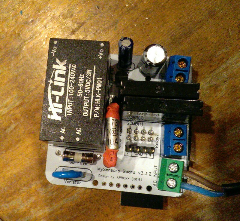
The Aproxx's board has Thermal Cutoffs, and i didn't see that in your project -
@tonnerre33 yep. you're right, it's cms I'm sorry :disappointed: I think.. good luck to fit everything with arduino mini in wall.
About the cutoff, I replaced this by a simple temperature sensor for monitoring. imho, i have two fuses onboards + varistor, enough for me comparing to some commercial products. If it burns you have a big problem somewhere!! But sure it's better to know what you do, thermal fuses is good ;) -
@tonnerre33 yep. you're right, it's cms I'm sorry :disappointed: I think.. good luck to fit everything with arduino mini in wall.
About the cutoff, I replaced this by a simple temperature sensor for monitoring. imho, i have two fuses onboards + varistor, enough for me comparing to some commercial products. If it burns you have a big problem somewhere!! But sure it's better to know what you do, thermal fuses is good ;)@scalz don't be sorry, i just need to learn to weld cms xd But for not disturb this project, i'll continue ta ask my questions in your topic project ;)
-
@tonnerre33 said:
But for command up/down, and in order to do an hardware protection, we can use an inversor relay.
I don't know if we need an inversor relay. For sure it will be hard to find another relay as small as these SSRs
Maybe I'm wrong but I from what I know roller shutter motors have a common ground and then you connect the phase for the direction you want to use. I think it can be done in software, with hardware it cannot be done on this PCB because of the way the SSRs are connected.@scalz on your board you use relays that are much bigger than those tiny SSRs, in the end it probably gives the same result for the space used on the board, and as you have the radio on the other side the depth difference is not very big, just 2mm from the plastic at the base of the connectors.
-
Hi I did everything according to the project and I have problem "error sending the switch command check device / hardware"
One change for me is 10nF capacitor instead of 100nF (I dont have now
)
Could this be the reasons this error?!
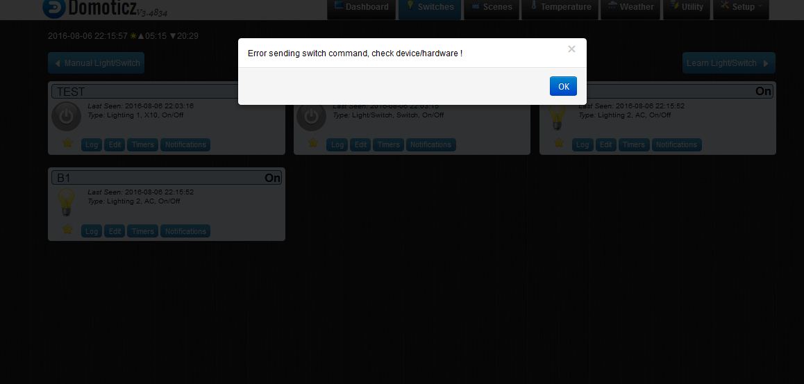
@okos if you have the device in Domoticz it means it could run, and send data to the gateway controller.
Did you change anything in hardware of software between the moment you added the node/sensor to Domoticz and the moment you tried to activate it ?
Are you sure your settings for the ACK are ok ? Maybe you are not sending one in the node but waiting from one in Domoticz ? Check the "Ack" column in Domoticz and if it's true try to change it to false. -
Aproxx you roxx. It works! Not sure what to do with it yet, but likely it will end up in a wall sometime soon on light duties. Thanks for sharing such a great design :-)
Hmm just pulled some switches, they are mostly SPDT jobbies on multiple switches, no idea how to hood this bad-boy up =( -
Hi everyone,
First I would like to thank the OP for sharing this great project :)
Then I would like to ask what would happen if the node cannot connect to the gateway on startup? It would still be possible to use the switch?
Thank you,
MySensors rules my home :)