Multisensor PIR based on IKEA Molgan
-
Think I have to visit ikea tomorrow, and bring home a couple of samples :)
Only about 5$...
-
7€ here...french conversion :angry:
it's at one hour from my home..but I think I will visit too this weekend. well done, now I can't wait :) -
Hi,
is it possible to describe, how to wire the original PIR, with the Arduino?I have some Molgan's here and want to mod them, if i can use the original PIR, it would be perfect :)
Maybe an HowTo?
Many Thanks
@Floca hi the Original Ikea Pir, I kind of destroyed during the "investigation". I my previous post I have posted a picture of the pir inside. I would feed the pir with either 2 or 3 batteries. (3/4,5v) after that you can either use the signal directly after the chip. Th is is 1,8v but I don't know if the arduino takes that as high..? If not you can take the signal at the resistors of the LEDs. The voltage level here is depending on your battery infeed. So either 3v or 4,5v. Don't think both will be a problem for the arduino. To eliminate the led you can take away one or more resistors.
Maybe somebody can say more
About the allowable Voltage levels. For battery live a 3v pro mini would be better. For ease of use a 5v version would be better -
I now have a fresh supply of Molgan to be modified. And I will post my modification of the existing board soon. Status I can now use the input of the existing PIR signal. And I have discovered that by sending out a high or low on one of the arduino pins I can switch the existing LED on / off. Of course I can use a relay function to control but as it is running on batteries the sensor has to sleep. I was thinking of sending out a parameter (true / false) which enables the sensor to activate the LED on a trigger of the PIR. How could I send over this parameter? Any (creative) idea's as the sensor is sleeping most of the time?
Now I am thinking of it, could it be possible that such a value is read by the sensor when the sensor is getting out of the sleep function.
-
In development branch there is a smartsleep function for receiving while sleeping (if I get it right)
-
In development branch there is a smartsleep function for receiving while sleeping (if I get it right)
@rollercontainer I could use the wait function
/**- Wait for a specified amount of time to pass or until specified message received. Keeps process()ing.
- This does not power-down the radio nor the Arduino.
- Because this calls process() in a loop, it is a good way to wait
- in your loop() on a repeater node or sensor that listens to messages.
- @param ms Number of milliseconds to sleep.
- @param cmd Command of incoming message.
- @param msgtype Message type.
*/
void wait(unsigned long ms, uint8_t cmd, uint8_t msgtype);
And wait for a message, which is send out by the controller (by a rule) after receiving the PIR trigger. But it is a kind of waste of energy to wait for a signal which is not frequently used. As far as I can read in the code this is exactly what smart sleep does. But can how can prepare a reply by the gateway that will respond to such a heartbeat?
-
@rollercontainer I could use the wait function
/**- Wait for a specified amount of time to pass or until specified message received. Keeps process()ing.
- This does not power-down the radio nor the Arduino.
- Because this calls process() in a loop, it is a good way to wait
- in your loop() on a repeater node or sensor that listens to messages.
- @param ms Number of milliseconds to sleep.
- @param cmd Command of incoming message.
- @param msgtype Message type.
*/
void wait(unsigned long ms, uint8_t cmd, uint8_t msgtype);
And wait for a message, which is send out by the controller (by a rule) after receiving the PIR trigger. But it is a kind of waste of energy to wait for a signal which is not frequently used. As far as I can read in the code this is exactly what smart sleep does. But can how can prepare a reply by the gateway that will respond to such a heartbeat?
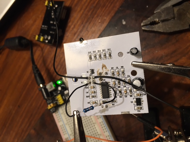
It is unfortunately not a full How-To yet. But basically the IKEA PIR is ready for operation.-
The PIR Runs on 3 Volt. There is a power regulator (U1). I am going to keep the 3 AAA batteries so I keep the regulator on the board.
-
I have removed the resistor (R17) and attached two wires to both the Original ends on the board. The one closest to the BISS0001 is your PIR signal. 3V when high and 0V for low. The other wire can be used to control the lights on the board. The wire is connected to the Q1 NPN transistor. Basically 3V high is on and 0V is off. But maybe you will also be able to dim the lights.
-
You also need to remove Resistor R11. The Original value is about 620 K and this will result in 30 seconds of ON after triggering. I have replaced it with 100 K and now it is about 5 seconds, a further reduction whill shorten this time lineair. So 10K = 0,5 sec. The PIR itself is retriggered.
-
With resistor R10 is controlling the time that the PIR cannot be triggered after a trigger. It is now approx 10K = 0,5 sec. So no need to change.
-
You need also to remove the photodiode on the front. Otherwise the PIR is only triggered when it is dark.
-
The powerconsumption of the PIR when not triggered is approx. 60 uA and when triggered 160 uA. So this is about the same as the standard PIR's. When the lights are activated the consumption is about 36 mA.
-
The PIR (without the hood) is quite sensitive. Even the slightest movement is already triggering the PIR.
-
It is unfortunately not a full How-To yet. But basically the IKEA PIR is ready for operation.-
The PIR Runs on 3 Volt. There is a power regulator (U1). I am going to keep the 3 AAA batteries so I keep the regulator on the board.
-
I have removed the resistor (R17) and attached two wires to both the Original ends on the board. The one closest to the BISS0001 is your PIR signal. 3V when high and 0V for low. The other wire can be used to control the lights on the board. The wire is connected to the Q1 NPN transistor. Basically 3V high is on and 0V is off. But maybe you will also be able to dim the lights.
-
You also need to remove Resistor R11. The Original value is about 620 K and this will result in 30 seconds of ON after triggering. I have replaced it with 100 K and now it is about 5 seconds, a further reduction whill shorten this time lineair. So 10K = 0,5 sec. The PIR itself is retriggered.
-
With resistor R10 is controlling the time that the PIR cannot be triggered after a trigger. It is now approx 10K = 0,5 sec. So no need to change.
-
You need also to remove the photodiode on the front. Otherwise the PIR is only triggered when it is dark.
-
The powerconsumption of the PIR when not triggered is approx. 60 uA and when triggered 160 uA. So this is about the same as the standard PIR's. When the lights are activated the consumption is about 36 mA.
-
The PIR (without the hood) is quite sensitive. Even the slightest movement is already triggering the PIR.
@dynamite Nice work!
I'm currently working on the following Molgan hack: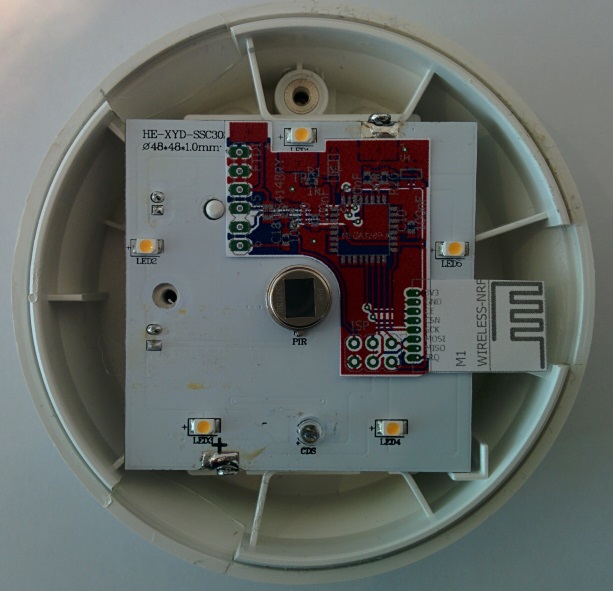
It is a small PCB (the red board) that overlays the original Molgan PCB.
The original PIR & electronics stay in place.
LEDs will remain functional (if you want) or can be partially removed to improve battery life, or completely to turn it into a motion-sensor only.
It uses an SMD nRF24 module, has a mounting spot for SHA204A, FTDI and ISP connectors.The layout is currently at the board house.
I'll report back when I get the PCBs and build one!http://yveaux.blogspot.nl
-
-
@dynamite Nice work!
I'm currently working on the following Molgan hack:It is a small PCB (the red board) that overlays the original Molgan PCB.
The original PIR & electronics stay in place.
LEDs will remain functional (if you want) or can be partially removed to improve battery life, or completely to turn it into a motion-sensor only.
It uses an SMD nRF24 module, has a mounting spot for SHA204A, FTDI and ISP connectors.The layout is currently at the board house.
I'll report back when I get the PCBs and build one! -
@Yveaux NICE! Can I get the files for the board as a sneak preview? Do you get the PIR signal / Light control from the same place as I was indicating?
@dynamite Send me your email in a chat and it comes your way.
I'll probably post it all on openhardware.io when it's finished and proven to work.
Fun thing is I tried the power usage of the original PIR with and without the regulator, and the power usage was actually less with the regulator than without :yum:
I'll use two of the three batteries to also power my addon board.
The trigger is taken from the top led, just below the battery cover screw in the picture.
I could take it from before the transistor, but this way I needed no extra wire.http://yveaux.blogspot.nl
-
@dynamite Send me your email in a chat and it comes your way.
I'll probably post it all on openhardware.io when it's finished and proven to work.
Fun thing is I tried the power usage of the original PIR with and without the regulator, and the power usage was actually less with the regulator than without :yum:
I'll use two of the three batteries to also power my addon board.
The trigger is taken from the top led, just below the battery cover screw in the picture.
I could take it from before the transistor, but this way I needed no extra wire. -
@Yveaux Sent you a DM with my email adress. Can't you use the voltage level after the regulator? The regulator is rated up to 30 mA.
Hello! It looks like you're interested in this conversation, but you don't have an account yet.
Getting fed up of having to scroll through the same posts each visit? When you register for an account, you'll always come back to exactly where you were before, and choose to be notified of new replies (either via email, or push notification). You'll also be able to save bookmarks and upvote posts to show your appreciation to other community members.
With your input, this post could be even better 💗
Register Login