Multisensor PIR based on IKEA Molgan
-
In development branch there is a smartsleep function for receiving while sleeping (if I get it right)
-
In development branch there is a smartsleep function for receiving while sleeping (if I get it right)
@rollercontainer I could use the wait function
/**- Wait for a specified amount of time to pass or until specified message received. Keeps process()ing.
- This does not power-down the radio nor the Arduino.
- Because this calls process() in a loop, it is a good way to wait
- in your loop() on a repeater node or sensor that listens to messages.
- @param ms Number of milliseconds to sleep.
- @param cmd Command of incoming message.
- @param msgtype Message type.
*/
void wait(unsigned long ms, uint8_t cmd, uint8_t msgtype);
And wait for a message, which is send out by the controller (by a rule) after receiving the PIR trigger. But it is a kind of waste of energy to wait for a signal which is not frequently used. As far as I can read in the code this is exactly what smart sleep does. But can how can prepare a reply by the gateway that will respond to such a heartbeat?
-
@rollercontainer I could use the wait function
/**- Wait for a specified amount of time to pass or until specified message received. Keeps process()ing.
- This does not power-down the radio nor the Arduino.
- Because this calls process() in a loop, it is a good way to wait
- in your loop() on a repeater node or sensor that listens to messages.
- @param ms Number of milliseconds to sleep.
- @param cmd Command of incoming message.
- @param msgtype Message type.
*/
void wait(unsigned long ms, uint8_t cmd, uint8_t msgtype);
And wait for a message, which is send out by the controller (by a rule) after receiving the PIR trigger. But it is a kind of waste of energy to wait for a signal which is not frequently used. As far as I can read in the code this is exactly what smart sleep does. But can how can prepare a reply by the gateway that will respond to such a heartbeat?
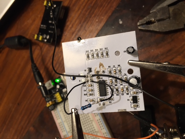
It is unfortunately not a full How-To yet. But basically the IKEA PIR is ready for operation.-
The PIR Runs on 3 Volt. There is a power regulator (U1). I am going to keep the 3 AAA batteries so I keep the regulator on the board.
-
I have removed the resistor (R17) and attached two wires to both the Original ends on the board. The one closest to the BISS0001 is your PIR signal. 3V when high and 0V for low. The other wire can be used to control the lights on the board. The wire is connected to the Q1 NPN transistor. Basically 3V high is on and 0V is off. But maybe you will also be able to dim the lights.
-
You also need to remove Resistor R11. The Original value is about 620 K and this will result in 30 seconds of ON after triggering. I have replaced it with 100 K and now it is about 5 seconds, a further reduction whill shorten this time lineair. So 10K = 0,5 sec. The PIR itself is retriggered.
-
With resistor R10 is controlling the time that the PIR cannot be triggered after a trigger. It is now approx 10K = 0,5 sec. So no need to change.
-
You need also to remove the photodiode on the front. Otherwise the PIR is only triggered when it is dark.
-
The powerconsumption of the PIR when not triggered is approx. 60 uA and when triggered 160 uA. So this is about the same as the standard PIR's. When the lights are activated the consumption is about 36 mA.
-
The PIR (without the hood) is quite sensitive. Even the slightest movement is already triggering the PIR.
-
It is unfortunately not a full How-To yet. But basically the IKEA PIR is ready for operation.-
The PIR Runs on 3 Volt. There is a power regulator (U1). I am going to keep the 3 AAA batteries so I keep the regulator on the board.
-
I have removed the resistor (R17) and attached two wires to both the Original ends on the board. The one closest to the BISS0001 is your PIR signal. 3V when high and 0V for low. The other wire can be used to control the lights on the board. The wire is connected to the Q1 NPN transistor. Basically 3V high is on and 0V is off. But maybe you will also be able to dim the lights.
-
You also need to remove Resistor R11. The Original value is about 620 K and this will result in 30 seconds of ON after triggering. I have replaced it with 100 K and now it is about 5 seconds, a further reduction whill shorten this time lineair. So 10K = 0,5 sec. The PIR itself is retriggered.
-
With resistor R10 is controlling the time that the PIR cannot be triggered after a trigger. It is now approx 10K = 0,5 sec. So no need to change.
-
You need also to remove the photodiode on the front. Otherwise the PIR is only triggered when it is dark.
-
The powerconsumption of the PIR when not triggered is approx. 60 uA and when triggered 160 uA. So this is about the same as the standard PIR's. When the lights are activated the consumption is about 36 mA.
-
The PIR (without the hood) is quite sensitive. Even the slightest movement is already triggering the PIR.
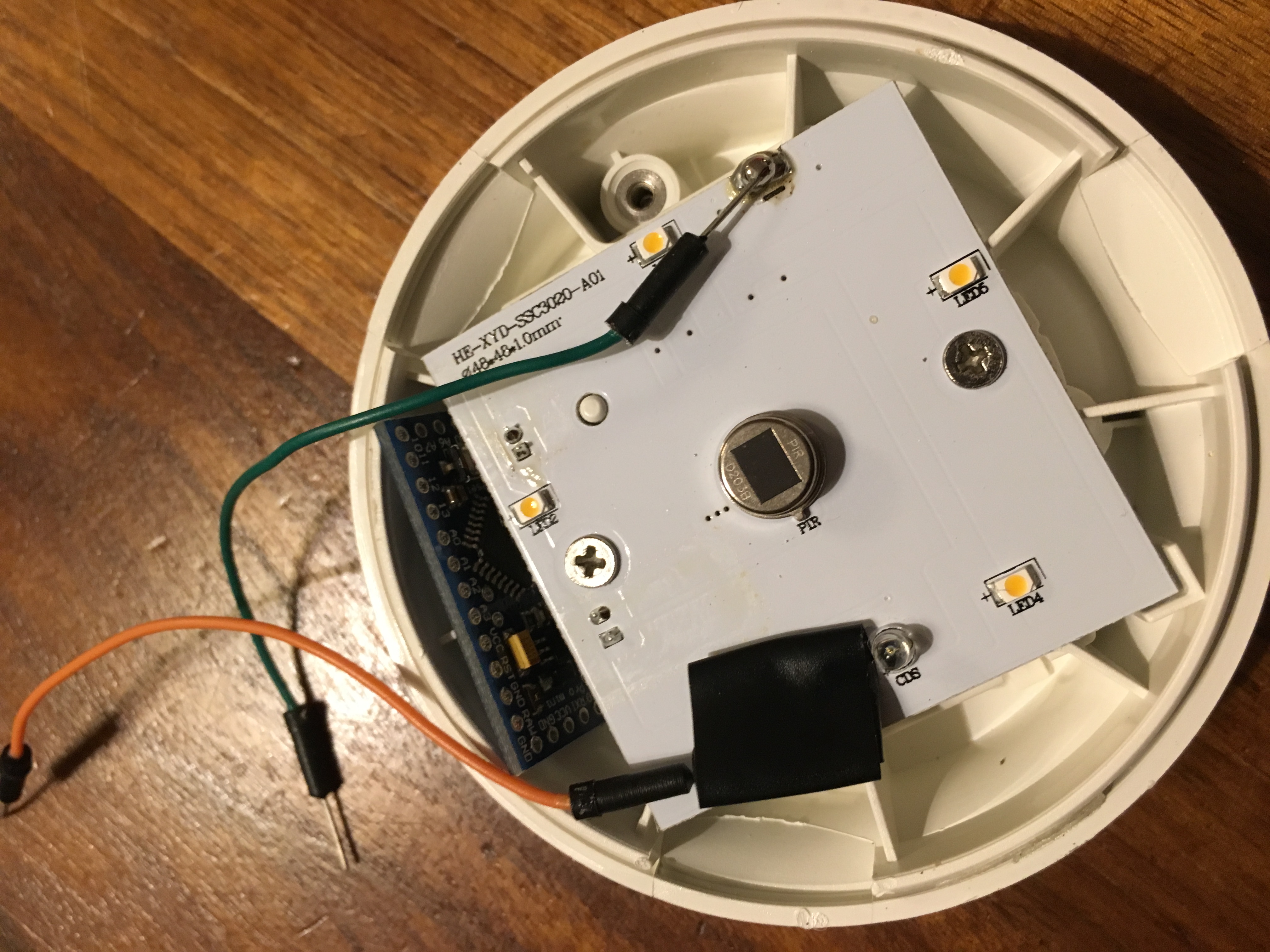
@dynamite Nice work!
I'm currently working on the following Molgan hack: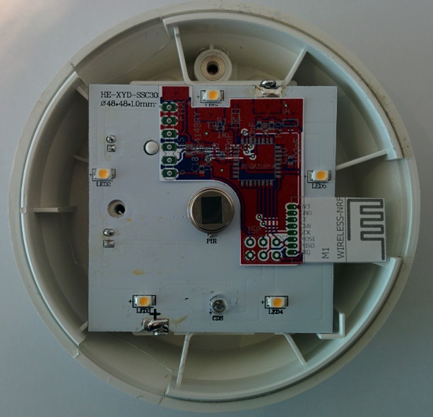
It is a small PCB (the red board) that overlays the original Molgan PCB.
The original PIR & electronics stay in place.
LEDs will remain functional (if you want) or can be partially removed to improve battery life, or completely to turn it into a motion-sensor only.
It uses an SMD nRF24 module, has a mounting spot for SHA204A, FTDI and ISP connectors.The layout is currently at the board house.
I'll report back when I get the PCBs and build one!http://yveaux.blogspot.nl
-
-
@dynamite Nice work!
I'm currently working on the following Molgan hack:It is a small PCB (the red board) that overlays the original Molgan PCB.
The original PIR & electronics stay in place.
LEDs will remain functional (if you want) or can be partially removed to improve battery life, or completely to turn it into a motion-sensor only.
It uses an SMD nRF24 module, has a mounting spot for SHA204A, FTDI and ISP connectors.The layout is currently at the board house.
I'll report back when I get the PCBs and build one! -
@Yveaux NICE! Can I get the files for the board as a sneak preview? Do you get the PIR signal / Light control from the same place as I was indicating?
@dynamite Send me your email in a chat and it comes your way.
I'll probably post it all on openhardware.io when it's finished and proven to work.
Fun thing is I tried the power usage of the original PIR with and without the regulator, and the power usage was actually less with the regulator than without :yum:
I'll use two of the three batteries to also power my addon board.
The trigger is taken from the top led, just below the battery cover screw in the picture.
I could take it from before the transistor, but this way I needed no extra wire.http://yveaux.blogspot.nl
-
@dynamite Send me your email in a chat and it comes your way.
I'll probably post it all on openhardware.io when it's finished and proven to work.
Fun thing is I tried the power usage of the original PIR with and without the regulator, and the power usage was actually less with the regulator than without :yum:
I'll use two of the three batteries to also power my addon board.
The trigger is taken from the top led, just below the battery cover screw in the picture.
I could take it from before the transistor, but this way I needed no extra wire. -
@Yveaux Sent you a DM with my email adress. Can't you use the voltage level after the regulator? The regulator is rated up to 30 mA.
-
This have to be posted on http://www.ikeahackers.net/ when done also.
-
@hek Will do just nice, next to the AK47 Hemma Lamp :flushed:
-
Did someone succeed in fitting a pro mini and radio in the Molgan while still using the original pir?
It looks to me there isn't enough room for the additional components and I'm not sure what part of the pcb I can saw off while still being able to use the original pir.Does anyone have an idea?
-
Did someone succeed in fitting a pro mini and radio in the Molgan while still using the original pir?
It looks to me there isn't enough room for the additional components and I'm not sure what part of the pcb I can saw off while still being able to use the original pir.Does anyone have an idea?
-
Bought 3 pcs. to open / modify / try fitting things in it. The thing is that this housing is really perfect to place it on the ceiling or to fit things in. Better than a black box.
What I'm going to try is remove all the plastic inside including the batteryhousing but not the "click"-system to mount it.
I'm going to try to make it 230 volt compatible with a HLK-PM01 so that I can use it as a PIR, Temp and door sensor and connect it at the ceiling.Let you know how things are working out!
-
@Sander-Stolk said:
door sensor and connect it at the ceiling
???
My house has its doors in the walls...@Yveaux said:
@Sander-Stolk said:
door sensor and connect it at the ceiling
???
My house has its doors in the walls...Well... connect a very small white wire in the hallway to the top of the door with a magnet.
With white ceilings you can put little cables like out of sight -
@Yveaux said:
@Sander-Stolk said:
door sensor and connect it at the ceiling
???
My house has its doors in the walls...Well... connect a very small white wire in the hallway to the top of the door with a magnet.
With white ceilings you can put little cables like out of sight -
@Sander-Stolk ah, OK. I think you can even run it all on batteries if you want
@Yveaux Yes it can BUT...
I have 0 succesfull attempts with a APM with removed regulator on 2 AA batteries. For some reason it draws power and within 3 days my batteries are dead. It's something that I will ask on the forum in a while but for now this works all the time so for it is the easy way :)