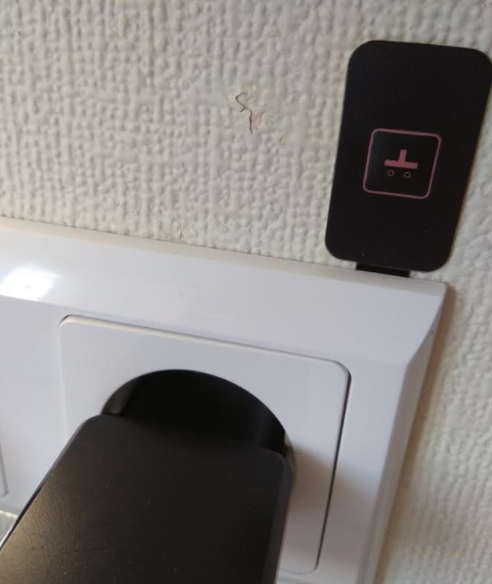
π¬ Wall Socket Insertable Node
-
bump! did you receive those?
-
Unfortunately everything that could go wrong went wrong.
So sample transformers are ready, sample boards are ready too. But I am expecting package with all my new boards and components only next week and hope to start testing soon.
-
Hi, will it also measure voltage or just current? Because to calculate power you need voltage as well? Is it possible to add dht22 and one wire temperature sensor to it as well, then it could replace all the temperature controllers for heating cables.
-
@skatun said:
Hi, will it also measure voltage or just current? Because to calculate power you need voltage as well? Is it possible to add dht22 and one wire temperature sensor to it as well, then it could replace all the temperature controllers for heating cables.
Hello. RFM69 module has built-in temperature sensor. If you look on the board carefully you will find a lot if arduino pins. You can use it for any sensors if it is critical for you.
What controllers are you referencing to?
About voltage... I think you know voltage in your sockets without any sensors with enough accuracyBoards and components are under customs clearance now... Expecting
-
@Koresh
Check out this interesting topic on accursy for power measurement:
GregDo you have data on the inbuilt temperature sensor?
-
@skatun said:
@Koresh
Check out this interesting topic on accursy for power measurement:
GregDo you have data on the inbuilt temperature sensor?
Frankly speaking I had added current sensor last night before test board production and I had no goal to measure power very accurate. The main goal of this sensor is ability to check fact of load (forget iron for example :)). Of course I can improve it in further versions, but it is not the main feature now.
I tested this temperature sensor and it works fine. I'am not sure mysensors library supports it. If it doesn't support it I will try to add this ability after hardware testing.
-
@Koresh Ok, I am looking forward to hear how your board turns out. So what I am looking for is something to replace this temperature controller. I was thinking about using esp8266 wifi chip instead of the radio, since power is not a big issue since its connected to the power line. Then people like my parents can use it with IFTTT and do not have to add a gateway. I was also thinking about adding a connector for a nextion display, just in case you want to display the temperature, use it as input to set temperature etc. It should also have a better temperature and humidity chip then the one inbuilt I think. Screw terminal to connect floor temperature sensor. Measure power accurately. Well if you would like to cooperate on version2 of your board let me know. I would like to make 20 units or so for now.
-
I'm having first success with this board. Power supply works!
-
@Koresh great work! You can still make July 30th :bowtie: no pressure :neckbeard:
-
And some photos after soldering of the main components and slight washing.
Relay trick
-
Hi Koresh. Interesting project ! Are you planning to sell some assembled parts too ?
-
I just bumped into these too:
https://www.openhardware.io/view/102/Wall-Switch-Insertable-Node#tabs-instructions
So interesting ! will these be sold too ?
-
@Sander-Teunissen
I will make a small presentation of new boards tomorrow in Breda. Of course I will try to start mass production asap You can check estimated prices of all boards in button size radionode thread.
-
Hi, it's a very intersting project but what about the protections of the switching power supply ?
I see a varistor but neither fuse nor Thermal Cutoffs.
-
@tonnerre33 do not worry. It will be in final version + we can use temperature sensor in rfm modult to switch of the relay.
-
Very nice to see this device today live in Breda
-
Very nice project. Looking forward to buy it. It would be nice to have possibility to trigger switch via local button (as in Fibaro) and not only via radio. It's possible from software point of view but board should be modified slightly. Is it in your todo list @Koresh?
-
@fisher are you referring to touch sensor button or momentary push button?
-
@yury yes
-
@fisher said:
Very nice project. Looking forward to buy it. It would be nice to have possibility to trigger switch via local button (as in Fibaro) and not only via radio. It's possible from software point of view but board should be modified slightly. Is it in your todo list @Koresh?
Thanks! We thought about this feature, thanks for your reminder. I've successully added pins for button. You can see new JST connector for button on the screenshot below. I hope this solution is reliable enough
I almost forgot... Now this board contains SPI flash which implements OTA upgrade ability
-
@Koresh Perfect! Do you know when the modules will be ready for sale? How they will be sold? Direct sale, ebay, ...?
Do you have further development plans, ex. dimmers, wall node with two relays, blind controllers?
-
@Koresh Another thing I forgot. Are you considering to design and sale any plastic case to your modules? Putting raw electronics to tight wall socket is not the safest solution
-
@fisher said:
@Koresh Another thing I forgot. Are you considering to design and sale any plastic case to your modules? Putting raw electronics to tight wall socket is not the safest solution
We plan to supply small plastic case because without this case it is impossible to get CE mark (it must be on the case). After buying you can extract the board and put it under socket if you want. But I do not agree with your thesis about safety. We tried to explain it in our presentation in Breda. The safest case - no case Do not forget this module will have all of fuses (thermal cutt off, overvoltage varistor, slow fuse) and of course we will do all possible steps to isolate danger points.
-
@Koresh Is there any video from Breda meeting?
-
@fisher said:
Putting raw electronics to tight wall socket is not the safest solution
We think to use as "standalone case" this one:
As for safety in "tight wall socket", the point here is:
- All those wall socket boxes is really safe Ip 20 or 44 certified together with socket itself.
- If something happens inside this crimped space will stay there.
This node will have thermal fuse, Over-voltage varistor, and if you short cut the relay - ACS 712 has build in "fuse".
So I think inside a wall is still much safer. How to put it safely there - it is another topic. At least you have to have experience in fixing things at home and for sure cut off power!
I tried to burn this thing many times as we tested it. so far most impressive was relay short cut test. Re-soldering new ACS712 fixed thing back. Relay survived also.
Traces of the test on the case. Not even melting traces, just smoked out:
-
Would it be possible for the diameter of the box to be smaller? In Germany the standard wall sockets are 68mm. So 60-65 mm fot the box would be ideal.
-
is the smallest. will get them soon. not sure if the thing will fit inside though.
So far we a bit stuck with our PCBA contractor. Negotiating hard for better prices.
-
Any update on your progress ? I am really watching out for this one !
-
@Sander-Teunissen Thanks for your attention to this project. There are Chinese national holidays until 8 october. So there are no updates now.
-
@Koresh This project looks super cool and very small. Thanks to the open hardware. Can you post SMPS transformer design specifications?
-
Hello, great project! I'm very intrested in it and waiting for testing results
One quick question: in this and also in other your profects with RFM69 you are don't using antenna for it. Is it not necessary, becose in introduction about radios (https://www.mysensors.org/build/connect_radio) there is note:
IMPORTANT: You MUST attach an antenna to the board. Aside from not working without an antenna, transmitters can be damaged if they transmit without an antenna present.
So does antenna for RFM69 is necessary?
Thanks!
-
@jacikaas Thanks for your attention. Of course antenna is necessary, I use 17cm wire as antenna for all projects (so flexible antenna :))
Unfortunately I was extremely busy last months. I became a father and I had a rush job with my work projects . But I hope I will have a little more time. Now I am waiting for the boards for the first relatively large batch of all my projects. I am waiting for the large pack of components too Also I found a reliable pcba partner (I hope). So I really hope to introduce my boards (preassembled) for purchase soon.
Latest version of this board, for example looks as these screenshots:
I also have very interesting new modifications of this and other boards (it is secret for now , but I will show it soon ).
-
I was looking for a gateway for the rfm69 chip. I just learned it is available in different frequencies. On which one of this component operating?
-
@Sander-Teunissen depend which rfm69 you will order. For example i have choosen 868Mhz, that's why i'll choose this frequency for all my nodes and my gateway
-
@Sander-Teunissen
315/433/868/915 MHz. I plan to mount 433Mhz for the first batch but it is easy to solder another if it necessary.
-
@Koresh thanks. I guess
https://www.openhardware.io/view/102/Wall-Switch-Insertable-Node
Will be 433 too then ?
-
@Sander-Teunissen Yes. Very soon I hope. This board (switch) contains only 0603 components now (without 0402 components), so it will be avaliable as kit for soldering funs too
12/06/2016 2:47 P.M. Your package is at the clearing agency awaiting final release.
It is components package... So I hope I will mount boards soon.
-
@Koresh great! Looking forward to it!
-
@tonnerre33 said:
@Sander-Teunissen depend which rfm69 you will order. For example i have choosen 868Mhz, that's why i'll choose this frequency for all my nodes and my gateway
I guess that's true when you do the board yourself.... But I am not tech savvy enough (or too lazy ) to do the board myself. I hope to buy them from Koresh directly...
-
Any update on this? This would scratch my latest itch!
-
@shabba said:
Any update on this? This would scratch my latest itch!
Both versions of this board are under intensive testing now. I've tuned it a little these days for working in very cold enveronment (it is very cold now in my country, up to -25-30C).
-
Great - Keep us informed!
-
@Koresh
Which type of transformer You are using (tr1)? type or order link?
THX,
MiKa
-
Hi Koresh,
Thanks for the last update and congratulations on finishing the design. You mentionned some time earlier that you wanted to sell these (and also CE approval?). Could you tell us the status of this?
Thanks,
Pierre
-
@PierreSt Many thanks for you attention to this project. I will add all assembled boards to Ebay next week. My devices successfully passed all safety tests. But unfortunatelly I have no enough resources to complete CE certification yet.
-
Hi @Koresh - Brilliant! I can't wait to order a whole pile of your boards!
Please shout when there are available!
-
Found it on ebay - is it yours Koresh?
http://www.ebay.com/usr/easysensors
For now there is only Wall Socket insertable node on stock, more boards will come soon I hope
-
Hi @fisher yes this is Koresh board. Hope to upload others soon... We did production and testing with him together.
-
@Koresh I'd like to repeat the question @MiKa asked on Januari 10th; can you share details on the transformer you used? Or a hint on where you got the inspiration for the power supply for the board?
-
@DavidZH Sorry for such long delay with this question. I will try to explain it carefully now.
I think it is not possible to buy ready transformer on ali or anywhere else. You can only derive it yourself according to your schematic and produce it at any factory according to your requirements.
This board has flyback power supply so you can use any flyback transformer design guide, or use as similar as possible reference design. I used EBC10010 reference design to produce the required transformer.
The main difficulty is the difference between theoretical transformers and produced transformers, so we should tune our schematic to produced transformer a little. Now I have a small batch of transformers almost all of which are soldered on the boards. When I place an order for the next batch of transformers (may be a larger one), I can who send it to anyone who is interested (of course with a tuned schematic if the next batch is different).
-
@Koresh Thanks for the explanation.
I've been searching for a power solution for my nodes. And that's quite the task.... For now I'm working with the HLK, but that's a tight squeeze. And when I want to make a dimmer, I could use a zero cross circuit. I've been looking into Vigortronix, who have a supply similar to the HLK, but with an extra pulse output for the zero-X. Too bad they are WIDE. They won't leave any proper room for a relay or connection terminal.
I'll take a look at your link and see if I can make that work in my case, and may come back to you for some magnetics.
-
Unfortunately I can't open my ebay shop right now. While I'm trying to open it, you can buy this board here: https://www.ebid.net/eu/for-sale/arduino-ide-compatible-low-profile-220v-10a-relay-rfm69hw-433-mhz-radio-156694939.htm
-
in case you want to use the wall plug manually when a device is connected (without mysensors), it will not work at all in case the relay has been switched ? How do you manage external usage ?
-
Assume you need to use it with some kind of momentary or rocker switch in case you lose connection to the gateway. Use JST connector and enable A2 internall pullup. JST connector pins are A2 and ground.
-
@yury i have built a system quite simular but still big mess in the connections. However, i am trying to have a detection when an equipment is plugged in into the wall plug to automatically activate the relay?
You may ask why? Simple reason. At home my wife doesnt use the automation system. If she plug in a device (charger, coffee machine, etc, it should work automatically without to have to switch the node via the mysensors controller. Normal usage of the plug should in my case be working.
-
@jeremushka In my opinion you should have two modes - automatic (with mysensors) and manualy (without). In manualy case the wall plug must be always under the voltage and you don't need detect plug a device. But how are you going to switch mode - this is a question...
-
@kalina said in Wall Socket Insertable Node:
But how are you going to switch mode - this is a question...
Long button pressure for example
-
@kalina agree with you. By pressing a button in that case better not to insert the system in the wall. To get outside plug. Something like the fibaro plug which is working with these two modes.
-
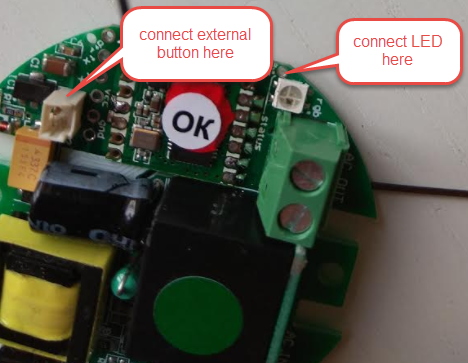
make sense?
sketch is here
https://github.com/EasySensors/WallSocketInsertableNode/blob/master/WallSocketInsertableNode.inobut no LED support there, but easy to add.
Yes, it will work if no gateway around.
-
@yury Yes, this is perfect Great job !!!
Have you ever had feature as power meter?
-
@jeremushka said in Wall Socket Insertable Node:
Have you ever had feature as power meter?
there is ACS712ELCTR-20A AC current sensing chip on the board. but Atmega ADC not very accurate at low currents reported from ACS712 - 20A. 15W loads or less can be difficult to recognize.
BTW another idea for LED indication . There is installed pixel LED on-board. check pictures. it is bright enough
-
@yury What do you think about capacitive button "On/Off" to the right corner from led? Look at the pic below...
-
@yury said in Wall Socket Insertable Node:
ACS712ELCTR-20A AC current
That will be great! for the current sensor, i am trying to check accurancy with another component HLW8012, it is used by Xiaomi as well. I don't know if it is good or not yet.
-
@jeremushka said in Wall Socket Insertable Node:
HLW8012
Very interesting solution. Except for one thing... According to HLW8012 appnote we need additional 5V power supply if we want to implement safety isolation between low voltage arduino circuit and high voltage circuit.
-
@Koresh could we reuse the 5V DC at the output of the transformer ? We have the isolation at this point. and the current will be enough for the the circuit.
-
@jeremushka Sorry but I don't understand... In current version of board ACS712 uses 5v DC from the transformer, but ACS output and power circuit are isolated from measure circuit. HLW8012 outputs and power are not isolated from measure circuit, so we should use circuit like this:
And of cource we need additional power supply.
-
@kalina said in Wall Socket Insertable Node:
@yury What do you think about capacitive button "On/Off" to the right corner from led? Look at the pic below...
Looks cool! Do you have experience with capacities switches? I did not play much with them. afraid to use close to AC interference though...
-
@yury I have a little experience with AD7148 and 7150 chips in one of my projects . You are right, there wasn't a high voltage traces.
-
@koresh Hi, I'm interested in the transformers. Do you have some to spare? I like your design very much because is so low profile. I will try to assemble some on my own to test the design but I have no idea where to find/order adequate transformer for it (you mentioned that you order them custom made). Thank you very much for the answer.
-
@yury said in Wall Socket Insertable Node:
Looks cool! Do you have experience with capacities switches? I did not play much with them. afraid to use close to AC interference though...
You need to use a capacitive IC with active shielding, basically you have an extra electrode around your touch electrode and the touch IC will compare capacitive change of the touch electrode with capacitive change from the shield electrode. If the change is due to electrical interference then both electrodes will be changed in a similar way and the IC will not trigger.