Solar Powered Soil Moisture Sensor
-
I think the problem is the nimh battery, this kind of partial charge/discharge cycles is more suitable for a li-ion battery. It's ok when used as a garden light because the battery will discharge completely during the night and will not have a memory effect, but with the low power usage of a sensor it will lose capacity quickly.
Also if the solar panel is 1.2V like one your picture I don't understand how it could have enough voltage to charge the battery after the voltage drop of the diode ? On the garden light I bought the solar panel is 2V so it's possible to charge the battery to 100% at 1.4V+
@Nca78
Yes it can be the NiMh battery, but it is actually run for days maybe weeks with out any problem.
Today I disconnect the power to ATmega and put it back directly and it started to work.
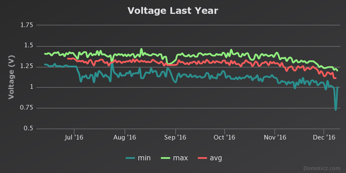
If the power goes below 0.8-0.9 it seems that I have to disconnect the step-up otherwise the solar panel cannot charge the battery.Solar panel is 1.4V and battery is 1.2V it seems to work and I have around 1.2-1.3 V during night
-
@breimann
It have been in use since I write this post.
I have had many problems with the nodes. I don't know if the problem is with my repeater node/GW.
Time to time is stop sending and then suddenly without restarting the node, it start to send again.
I have restarted the nodes sometimes also.
Maybe it is to "small" solar panel so it takes time for it to recharge the battery?
If you will do a solar panel node, go for a big panel with high mA output and also a big battery(1000mA), I am using 1.2 v battery. I think it is much better to use at least 2.5 volt battery then you don't need the step-up. -
@Nca78
Yes it can be the NiMh battery, but it is actually run for days maybe weeks with out any problem.
Today I disconnect the power to ATmega and put it back directly and it started to work.
If the power goes below 0.8-0.9 it seems that I have to disconnect the step-up otherwise the solar panel cannot charge the battery.Solar panel is 1.4V and battery is 1.2V it seems to work and I have around 1.2-1.3 V during night
guys seriously this is just yet another reason to write your reporting interval based on battery voltage and time and not on time alone.
You are using extremely cheap systems with cheap batteries of unknown age that are likely very prone to incur reduced capacity over shorter times and memory from discharge cycles.
See the posts above. This really is one of the greatest ideas I have seen for monitoring, just needs a tweak
With these findings I would set a floor voltage around 1-1.1 V for the arduino to go into sleep mode (find your own floor voltage by looking at your sleep discharge rate and length of night time).
-
Hi all, I was so impressed by this thread that I decided to build my own. I must have spent maybe £6 or so - I really pushed the boat out. :smiley:
It's been running successfully for a few weeks now, so I thought I'd share my code and a few pics. I upgraded the original code to v2.0. I've kept the update frequency high and it's running just fine, but we'll see how it goes in winter with less sun.
Pics!
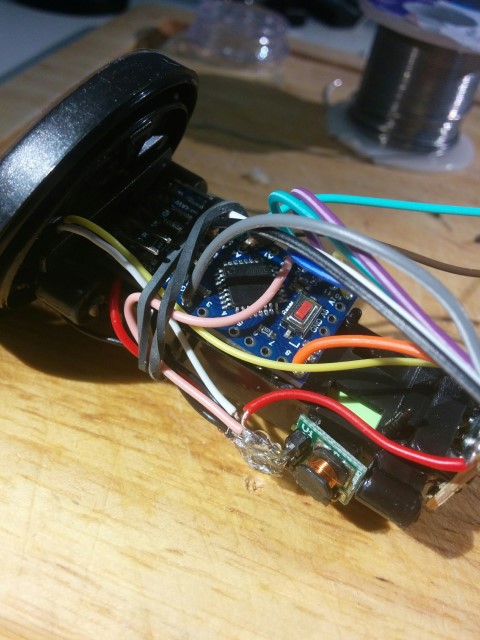
Here you can see the boost converter and the Arduino pro mini.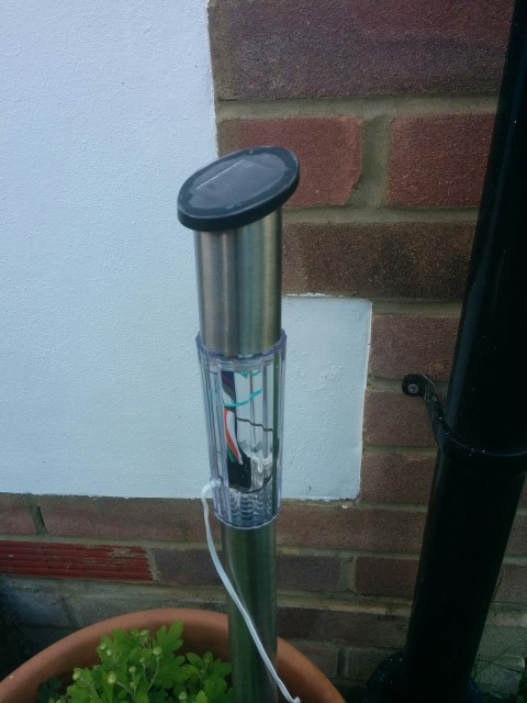
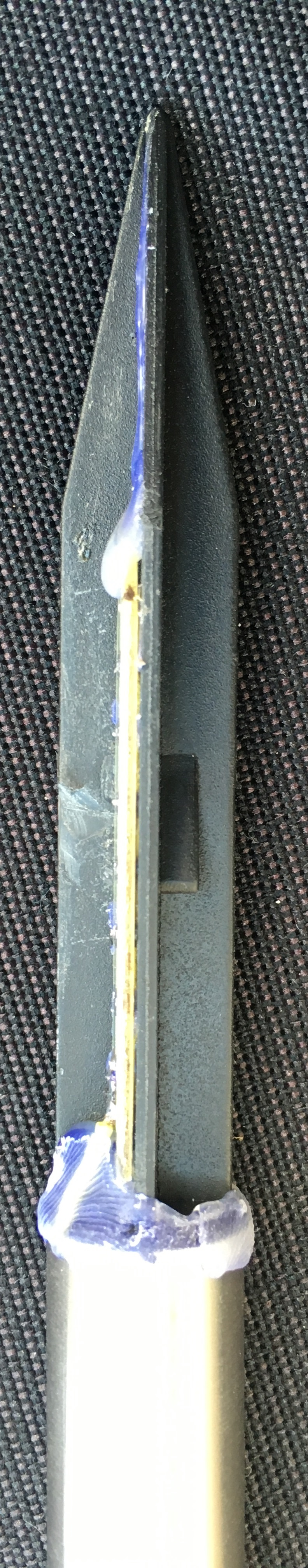
Here you can see the finished product in its natural environment. The RF radio sits in the plastic area, as I figured the metal collar at the top (where the arduino + battery sits) would have blocked/reduced the RF transmission.Code to follow.
-
I meant to mention that the wires coming out of the bottom are the wires that go to the soil moisture probes.
Here's the code in case anyone else would like it:
// Updated to v2.0 of Mysensors

// Enable debug prints
#define MY_DEBUG
#define MY_RADIO_NRF24

#include <MySensors.h>
#include <SPI.h>

#define round(x) ((x)>=0?(long)((x)+0.5):(long)((x)-0.5))
#define N_ELEMENTS(array) (sizeof(array)/sizeof((array)[0]))

#define CHILD_ID_MOISTURE 0
#define CHILD_ID_BATTERY 1
#define SLEEP_TIME 10000 // Sleep time between reads (in milliseconds), was 10000
#define THRESHOLD 1.1 // Only make a new reading with reverse polarity if the change is larger than 10%.
#define STABILIZATION_TIME 1000 // Let the sensor stabilize before reading default BOD settings
const int SENSOR_ANALOG_PINS[] = {A4, A5}; // Sensor is connected to these two pins. Avoid A3 if using ATSHA204. A6 and A7 cannot be used because they don't have pullups.

// MySensor gw;   //removed for v2.0
MyMessage msg(CHILD_ID_MOISTURE, V_HUM);
MyMessage voltage_msg(CHILD_ID_BATTERY, V_VOLTAGE);
long oldvoltage = 0;
byte direction = 0;
int oldMoistureLevel = -1;
float batteryPcnt;
float batteryVolt;
int LED = 5;

void setup()
{
  pinMode(LED, OUTPUT);
  digitalWrite(LED, HIGH);
  delay(200);
  digitalWrite(LED, LOW);
  delay(200);
  digitalWrite(LED, HIGH);
  delay(200);
  digitalWrite(LED, LOW);

  //  gw.begin(); //Removed for v2.0
  for (int i = 0; i < N_ELEMENTS(SENSOR_ANALOG_PINS); i++) {
    pinMode(SENSOR_ANALOG_PINS[i], OUTPUT);
    digitalWrite(SENSOR_ANALOG_PINS[i], LOW);
  }
}

void presentation(){  //created for v2.0
  sendSketchInfo("Plant moisture w solar", "1.0");
  present(CHILD_ID_MOISTURE, S_HUM);
  delay(250);
  present(CHILD_ID_BATTERY, S_MULTIMETER);
}


void loop()
{
  int moistureLevel = readMoisture();

  // Send rolling average of 2 samples to get rid of the "ripple" produced by different resistance in the internal pull-up resistors
  // See http://forum.mysensors.org/topic/2147/office-plant-monitoring/55 for more information
  if (oldMoistureLevel == -1) { // First reading, save current value as old
    oldMoistureLevel = moistureLevel;
  }
  if (moistureLevel > (oldMoistureLevel * THRESHOLD) || moistureLevel < (oldMoistureLevel / THRESHOLD)) {
    // The change was large, so it was probably not caused by the difference in internal pull-ups.
    // Measure again, this time with reversed polarity.
    moistureLevel = readMoisture();
  }
  send(msg.set((moistureLevel + oldMoistureLevel) / 2.0 / 10.23, 1));
  oldMoistureLevel = moistureLevel;

  int sensorValue = analogRead(A0);
  Serial.print("--Sensor value:");Serial.println(sensorValue);
  float voltage=sensorValue*(3.3/1023);
  Serial.print("--Voltage:");Serial.println(voltage);
  batteryPcnt = (sensorValue - 248) * 0.72;
  Serial.print("--Battery %:");Serial.println(batteryPcnt);
  batteryVolt = voltage;
  sendBatteryLevel(batteryPcnt);
  resend((voltage_msg.set(batteryVolt, 3)), 10);
  //send(voltage_msg.set(batteryVolt), 3);

  //flash led to indicate send
  digitalWrite(LED, HIGH);
  delay(200);
  digitalWrite(LED, LOW);

  sleep(SLEEP_TIME);
}

void resend(MyMessage &msg, int repeats)
{
  int repeat = 1;
  int repeatdelay = 0;
  boolean sendOK = false;

  send(msg);
/*
  while ((sendOK == false) and (repeat < repeats)) {
    if (send(msg)) {
      sendOK = true;
    } else {
      sendOK = false;
      Serial.print("Error ");
      Serial.println(repeat);
      repeatdelay += 500;
    } repeat++; delay(repeatdelay);
  }*/
}


int readMoisture() {
  pinMode(SENSOR_ANALOG_PINS[direction], INPUT_PULLUP); // Power on the sensor
  analogRead(SENSOR_ANALOG_PINS[direction]);// Read once to let the ADC capacitor start charging
  sleep(STABILIZATION_TIME);
  int moistureLevel = (1023 - analogRead(SENSOR_ANALOG_PINS[direction]));

  // Turn off the sensor to conserve battery and minimize corrosion
  pinMode(SENSOR_ANALOG_PINS[direction], OUTPUT);
  digitalWrite(SENSOR_ANALOG_PINS[direction], LOW);

  direction = (direction + 1) % 2; // Make direction alternate between 0 and 1 to reverse polarity which reduces corrosion
  return moistureLevel;
}
My thanks to flopp for the cool idea and to everyone else on the thread for the contributions.
-
Interesting project. To what degree, if any, has corrosion been a problem after you switched to soldered connections? Obviously the operating environment (near the ground outdoors) can be intrinsically humid.
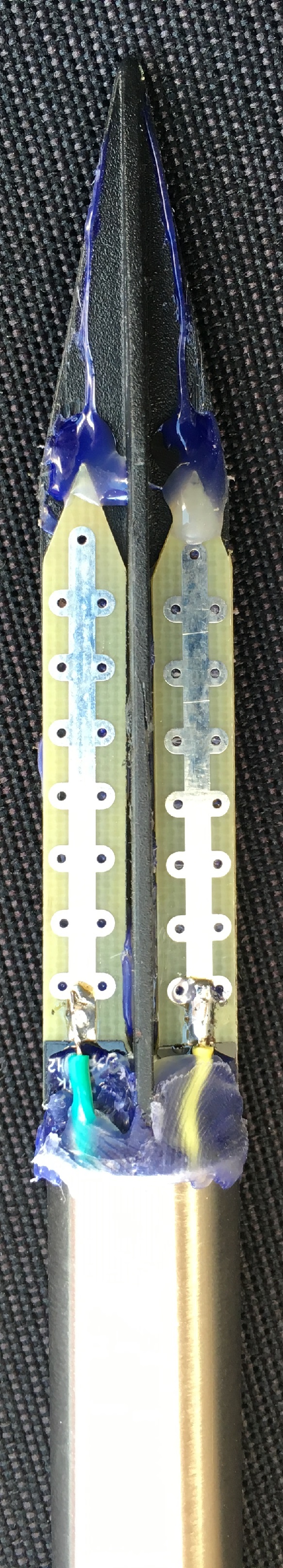
Also, can someone please post a larger photo of how the sensor is attached at the base? The area of interest on the photo provided is miniscule, and it's too grainy if I try to enlarge it to a better size:
-
Interesting project. To what degree, if any, has corrosion been a problem after you switched to soldered connections? Obviously the operating environment (near the ground outdoors) can be intrinsically humid.
Also, can someone please post a larger photo of how the sensor is attached at the base? The area of interest on the photo provided is miniscule, and it's too grainy if I try to enlarge it to a better size:
By the way, I notice this guy has a rather interesting soil moisture sensor that appears to go beyond measuring mere electrical conductance: https://www.tindie.com/products/Power_Modules/fdr-100mhz-plant-soil-sensor-mineral-transparency/
-
@flopp Can you please include the pictures in your posting as the "tinypic.com" is rather intrusive, thanks...
-
Interesting project. To what degree, if any, has corrosion been a problem after you switched to soldered connections? Obviously the operating environment (near the ground outdoors) can be intrinsically humid.
Also, can someone please post a larger photo of how the sensor is attached at the base? The area of interest on the photo provided is miniscule, and it's too grainy if I try to enlarge it to a better size:
@NeverDie said:
Interesting project. To what degree, if any, has corrosion been a problem after you switched to soldered connections? Obviously the operating environment (near the ground outdoors) can be intrinsically humid.
I have not checked how the sensor look like now, but I have only run it for 6 months. I have always used soldered connections.
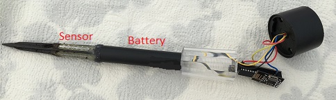
Also, can someone please post a larger photo of how the sensor is attached at the base?
-
By the way, I notice this guy has a rather interesting soil moisture sensor that appears to go beyond measuring mere electrical conductance: https://www.tindie.com/products/Power_Modules/fdr-100mhz-plant-soil-sensor-mineral-transparency/
-
@NeverDie said:
Interesting project. To what degree, if any, has corrosion been a problem after you switched to soldered connections? Obviously the operating environment (near the ground outdoors) can be intrinsically humid.
I have not checked how the sensor look like now, but I have only run it for 6 months. I have always used soldered connections.
Also, can someone please post a larger photo of how the sensor is attached at the base?
@flopp
Perfect! Thanks a bunch. I like it. Very clever.I think you were wise to cover the insulated wire with the silicon. Despite the appearance of being waterproof, I've noticed that regular wire insulation isn't waterproof/vaporproof, and regular wires used outdoors don't survive well (especially "copper" wires from China, which tend to have a high iron content and thus literally rust their way to failure). I don't know that silicon is sufficient, but if it isn't it might at least slow down the degradation process. It takes some effort to put these things together, so plainly you want them to last as long as possible.
Nice work!
-
WARNING!!!
I opened one of my items which didn't worked since many weeks ago.
I putted it on a table and should just open the stuff when I saw some brown water coming out from the pole.
My first guess was that it was water mixed with mud but the smell was strange. It can be that the battery has leaked.If you will build this item please seal the battery to 100%. I just put the battery in the pole but unfortunately water came in and what I think destroyed the battery!
Be careful
-
@flopp is your code should work with new version of gateway 2.1.1?
Just maked using this tutorial my gateway https://www.mysensors.org/build/raspberry and I'm getting nothing in debug...pi@raspberrypi:~/MySensors $ sudo ./bin/mysgw -d mysgw: Starting gateway... mysgw: Protocol version - 2.1.1 mysgw: MCO:BGN:INIT GW,CP=RNNG---,VER=2.1.1 mysgw: TSM:INIT mysgw: TSF:WUR:MS=0 mysgw: !TSM:INIT:TSP FAIL mysgw: TSM:FAIL:CNT=1 mysgw: TSM:FAIL:PDT mysgw: TSM:FAIL:RE-INITIn node I used your newest code for gw2.0 - is this because version mismatch or something different in my setup?
Could you update your code to work with new version? -
@flopp is your code should work with new version of gateway 2.1.1?
Just maked using this tutorial my gateway https://www.mysensors.org/build/raspberry and I'm getting nothing in debug...pi@raspberrypi:~/MySensors $ sudo ./bin/mysgw -d mysgw: Starting gateway... mysgw: Protocol version - 2.1.1 mysgw: MCO:BGN:INIT GW,CP=RNNG---,VER=2.1.1 mysgw: TSM:INIT mysgw: TSF:WUR:MS=0 mysgw: !TSM:INIT:TSP FAIL mysgw: TSM:FAIL:CNT=1 mysgw: TSM:FAIL:PDT mysgw: TSM:FAIL:RE-INITIn node I used your newest code for gw2.0 - is this because version mismatch or something different in my setup?
Could you update your code to work with new version?