💬 In Wall AC/DC Pcb (with Relay) for MySensors (SMD)
-
Hi folks, I manage to solder all the tiny pieces together and now I need some advice on uploading some code/sketch. To start with... is there any instruction for dummies on internet how to upload sketch through ICSP ? I have one arduino which can be programmer, but I don't know how to do it. Then there is question about powering circuit during uploading code.... is it OK if it's connect to AC power during uploading code? And finally, can anyone post some simple sketch for this board to check if everythiing is working? Thanks for help.
@nightbodom Arduino have a tutorial for this https://www.arduino.cc/en/Tutorial/ArduinoISP
-
@hugch thanks for info. I also find this: https://www.arduino.cc/en/Tutorial/ArduinoToBreadboard for burning bootloader. And after that... how should I upload sketch?
-
@hugch thanks for info. I also find this: https://www.arduino.cc/en/Tutorial/ArduinoToBreadboard for burning bootloader. And after that... how should I upload sketch?
@nightbodom you connect it to a ISP programmer to the port. This will take care of 5v and Gnd as well so don't connect to AC during upload
-
@sundberg84 so I use ISP programmer for burning bootloader... but after that how can i upload sketch... usualy I use FTDI programmer for proMINI ect. but here I don't see TX/RX... so how do you upload sketch?
-
@sundberg84 so I use ISP programmer for burning bootloader... but after that how can i upload sketch... usualy I use FTDI programmer for proMINI ect. but here I don't see TX/RX... so how do you upload sketch?
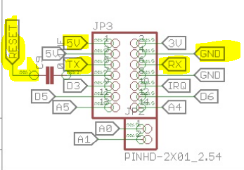
@nightbodom / either you use the isp to program the sketch without the bootloader or you can use the MysX connector where you will find all the necessary pins for ftdi.
-
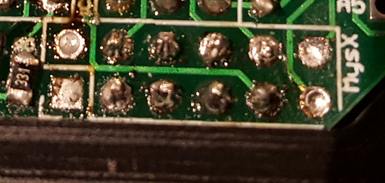
@sundberg84 thanks for advice... I successfully load bootloader through ISP with spare Uno as programmer, then I try to load a sketch with ftdi but it didn't recognize PCB. I also try with arduino uno as ISP and it goes without problem. I use node manager sketch with relay and connect it to AC wires...and nothing!
After visual checking of PCB I check fuses and notice that thermal fuse is dead. So I think I burn it with soldering. Any advice how to solder it? -
@sundberg84 thanks for advice... I successfully load bootloader through ISP with spare Uno as programmer, then I try to load a sketch with ftdi but it didn't recognize PCB. I also try with arduino uno as ISP and it goes without problem. I use node manager sketch with relay and connect it to AC wires...and nothing!
After visual checking of PCB I check fuses and notice that thermal fuse is dead. So I think I burn it with soldering. Any advice how to solder it?@nightbodom - this can be a bit tricky. Some suggest cooling pincers or tongs to hold it while soldering. Myself I solder as normal and wait it to cool down before continue. As long as you are quick and not heat it up to much it should work.
If you power the pcb with FTDI it should work without the fuse though. But I guess you power it through AC->HLK and use only RX/TX/GND and Rst from ftdi?
-
@sundberg84 thanks for advice... I successfully load bootloader through ISP with spare Uno as programmer, then I try to load a sketch with ftdi but it didn't recognize PCB. I also try with arduino uno as ISP and it goes without problem. I use node manager sketch with relay and connect it to AC wires...and nothing!
After visual checking of PCB I check fuses and notice that thermal fuse is dead. So I think I burn it with soldering. Any advice how to solder it?@nightbodom I use crocodile clips and get fairly good results with very few dead fuses....
-
-
Hi sundberg84,
can you maybe take a look on my board. I have rebuild it so you can use it with rfm69 and NRF24 moduls. I have build an adapter, which will stand vertical behin the HLK-PM01.
But how can I upload a picture?@grave Sure, you can just copy it into the message box.
-
@grave - at first it looks really good. Hard for me on a image to check every connection but I can not see any errors.