Scene Controller
-
Can i use Arduino Uno to make scene controller? If okie, please teach me to do it? thanks
Yes, but you cannot use the touch screen. Here is a couple of example of scene activators using buttons:
http://forum.mysensors.org/topic/1018/contest-3d-printed-battery-powered-wall-remote-control
http://forum.mysensors.org/topic/93/weather-station-with-scene-activator -
Bringing back an old thread. As you can tell, I'm not much of a developer. ..... apologies....
I'm updating all of my sensors to 1.5 but am having issues with this one. When I compile (using IDE 1.6.5) and a new libraries directory, I get the following error.
Any ideas?
TouchDisplaySceneControllerSensor:67: error: no matching function for call to 'MySensor::MySensor(int, int)' TouchDisplaySceneControllerSensor.ino:67:18: note: candidates are: In file included from TouchDisplaySceneControllerSensor.ino:37:0: C:\Users\tbully\Documents\Arduino\libraries\MySensors/MySensor.h:158:2: note: MySensor::MySensor(MyTransport&, MyHw&) MySensor(MyTransport &radio =*new MyTransportNRF24(), MyHw &hw=*new MyHwDriver() ^ C:\Users\tbully\Documents\Arduino\libraries\MySensors/MySensor.h:158:2: note: no known conversion for argument 1 from 'int' to 'MyTransport&' C:\Users\tbully\Documents\Arduino\libraries\MySensors/MySensor.h:149:7: note: MySensor::MySensor(const MySensor&) class MySensor ^ C:\Users\tbully\Documents\Arduino\libraries\MySensors/MySensor.h:149:7: note: candidate expects 1 argument, 2 provided no matching function for call to 'MySensor::MySensor(int, int)' -
Thanks @awi. I meant to come back and correct my post. I did see that after going back and looking at the old 1.4 API (you are correct). It has been many months since I've looked at this sketch. However, I'm not using the default PINs here so I guess I have to change MyConfig for this sketch?
/********************************** * NRF24L01 Driver Defaults ***********************************/ #define RF24_CE_PIN 9 #define RF24_CS_PIN 10 -
Thanks @awi. I meant to come back and correct my post. I did see that after going back and looking at the old 1.4 API (you are correct). It has been many months since I've looked at this sketch. However, I'm not using the default PINs here so I guess I have to change MyConfig for this sketch?
/********************************** * NRF24L01 Driver Defaults ***********************************/ #define RF24_CE_PIN 9 #define RF24_CS_PIN 10@tbully The new API uses a separate radio class initiator Something like (from one of my own 'learnings' , Ceech board in this case)
MyTransportNRF24 transport(7, 8); // Sensoduino (8,7) Ceech board, 3.3v (7,8) (pin default 9,10) MySensor gw(transport); -
Bringing back this old thread as I am building the scene controller now.
I am having a problem with a lot of garbage like this:send: 7-7-0-0 s=255,c=3,t=15,pt=2,l=2,sg=0,st=ok:0 send: 7-7-0-0 s=255,c=0,t=17,pt=0,l=5,sg=0,st=ok:1.5.2 send: 7-7-0-0 s=255,c=3,t=6,pt=1,l=1,sg=0,st=ok:0 read and drop: 7-7-0 s=255,c=3,t=6,pt=1,l=1,sg=0:0 read and drop: 0-224-0 s=0,c=0,t=0,pt=0,l=0,sg=0: ver mismatch read and drop: 0-224-0 s=0,c=0,t=0,pt=0,l=0,sg=0: ver mismatch ..... goes on and onI do not have different MySensors GW/nodes. All of my GW/Nodes have MYS 1.5.2 Where does ver mismatch come from? Also time is not getting pulled into the scene controller from the controller (Domoticz).
Cannot get time from the controller either... -
Bringing back this old thread as I am building the scene controller now.
I am having a problem with a lot of garbage like this:send: 7-7-0-0 s=255,c=3,t=15,pt=2,l=2,sg=0,st=ok:0 send: 7-7-0-0 s=255,c=0,t=17,pt=0,l=5,sg=0,st=ok:1.5.2 send: 7-7-0-0 s=255,c=3,t=6,pt=1,l=1,sg=0,st=ok:0 read and drop: 7-7-0 s=255,c=3,t=6,pt=1,l=1,sg=0:0 read and drop: 0-224-0 s=0,c=0,t=0,pt=0,l=0,sg=0: ver mismatch read and drop: 0-224-0 s=0,c=0,t=0,pt=0,l=0,sg=0: ver mismatch ..... goes on and onI do not have different MySensors GW/nodes. All of my GW/Nodes have MYS 1.5.2 Where does ver mismatch come from? Also time is not getting pulled into the scene controller from the controller (Domoticz).
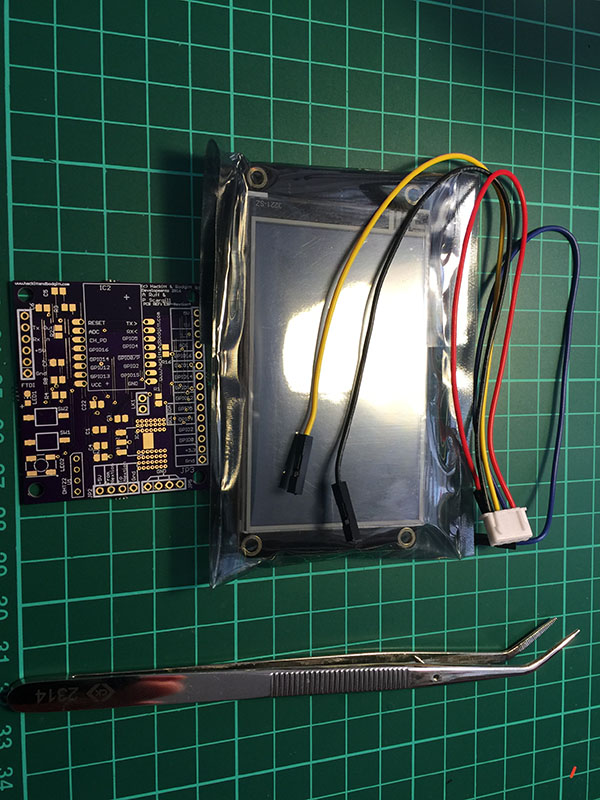
Cannot get time from the controller either...OK, just to revive this project, I decided to modify it as follows:
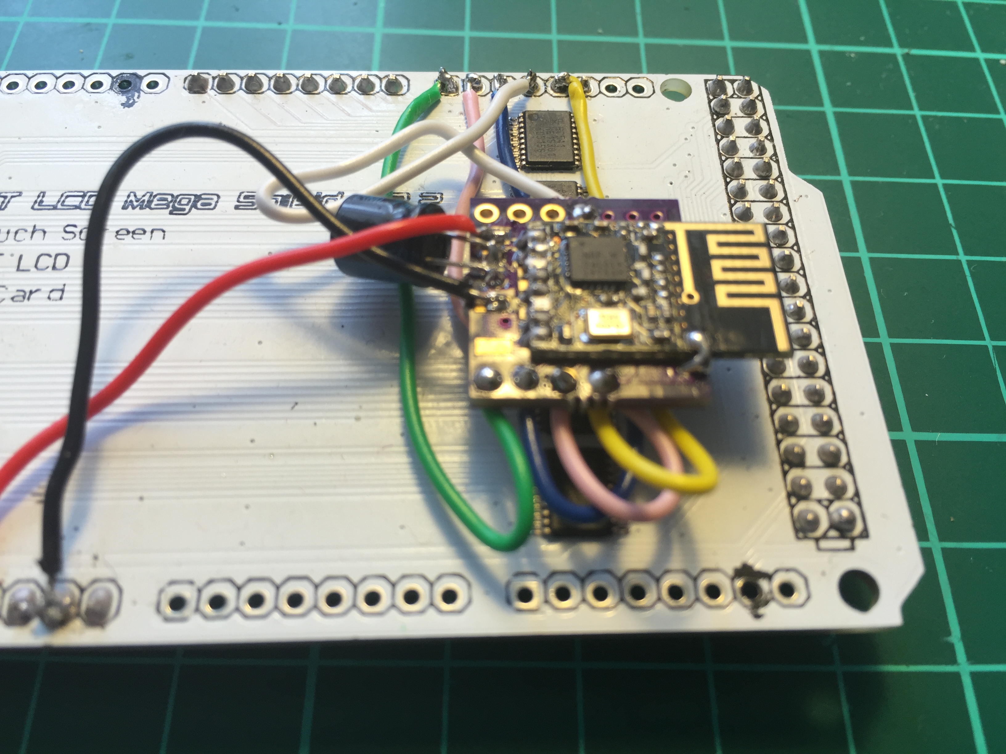
This would make the transmitter fit between the screen and the adapter
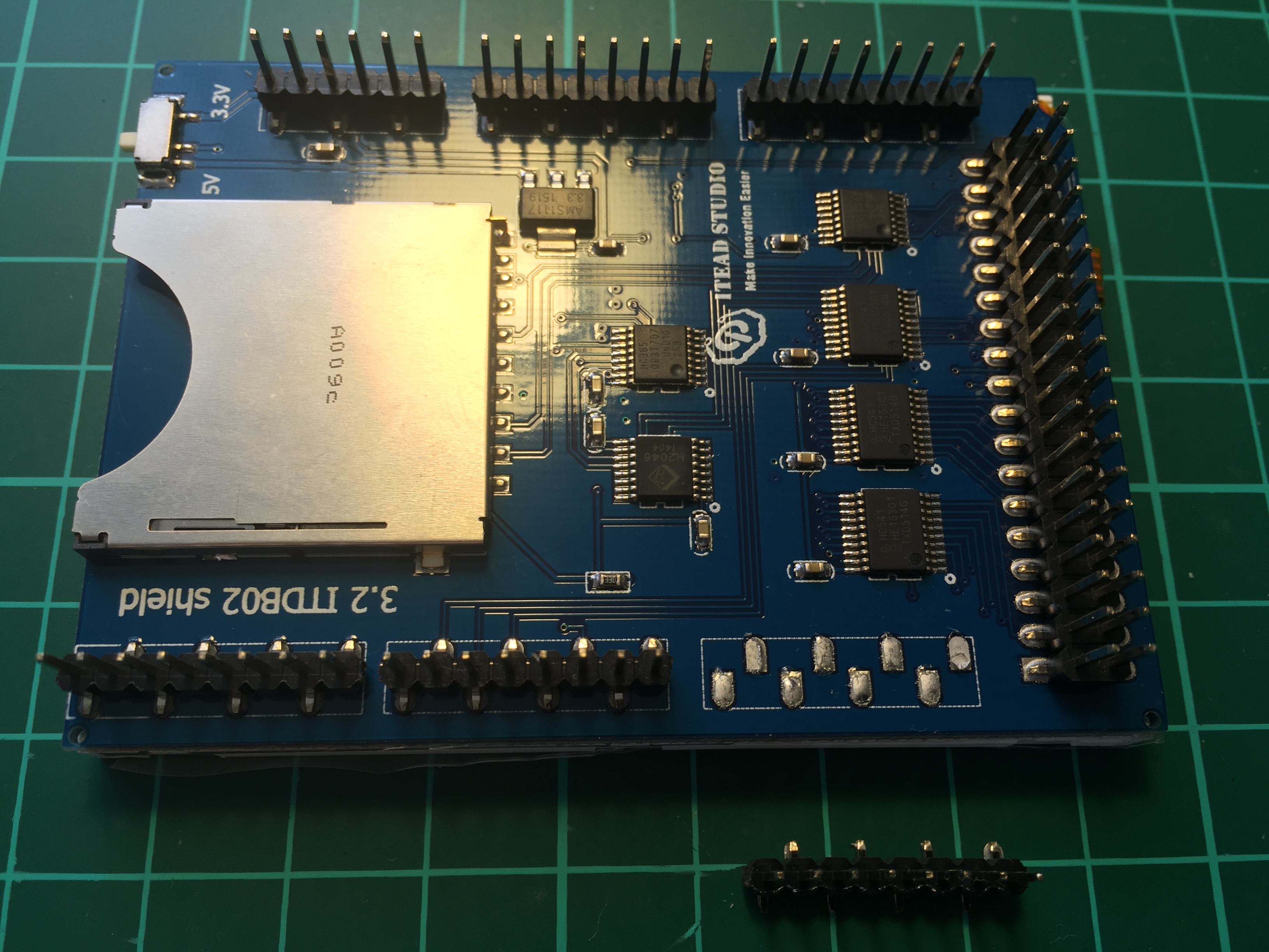
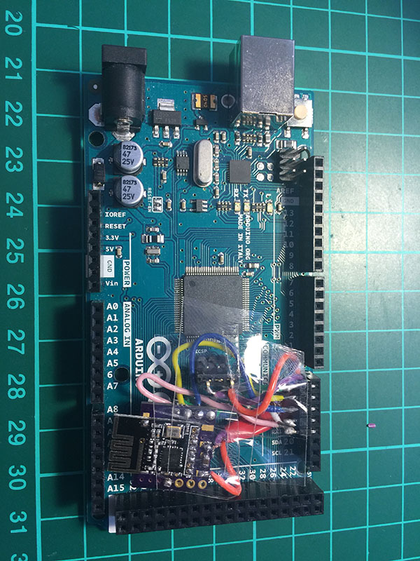
The problem is that this sandwich is super thick. So I got a new screen from itead studio, which can be used without the adapter. In this photo I desoldered D14-D21 pins as they are not used in order to hook up nrf24l01+:
-
OK, just to revive this project, I decided to modify it as follows:
This would make the transmitter fit between the screen and the adapter
The problem is that this sandwich is super thick. So I got a new screen from itead studio, which can be used without the adapter. In this photo I desoldered D14-D21 pins as they are not used in order to hook up nrf24l01+:
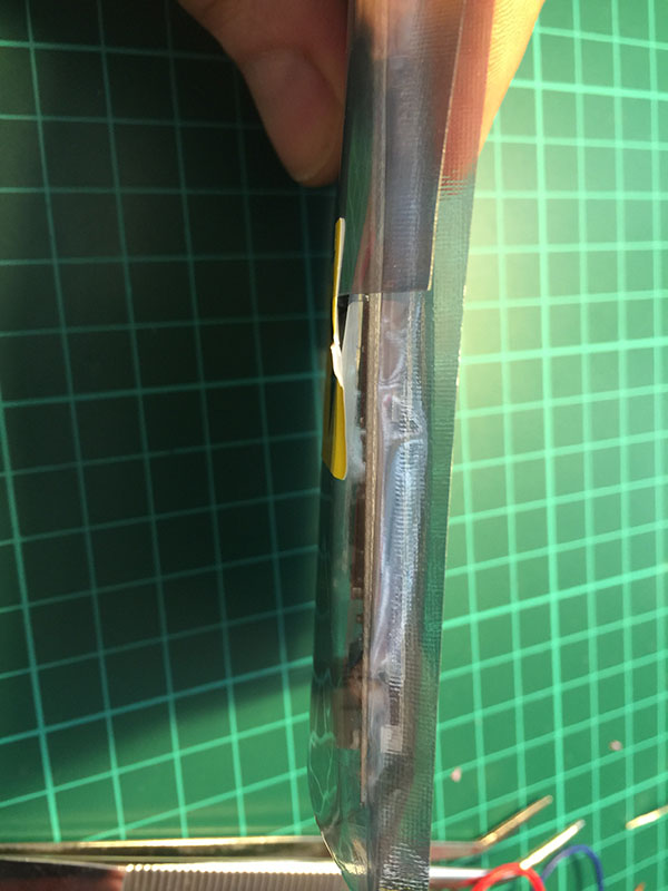
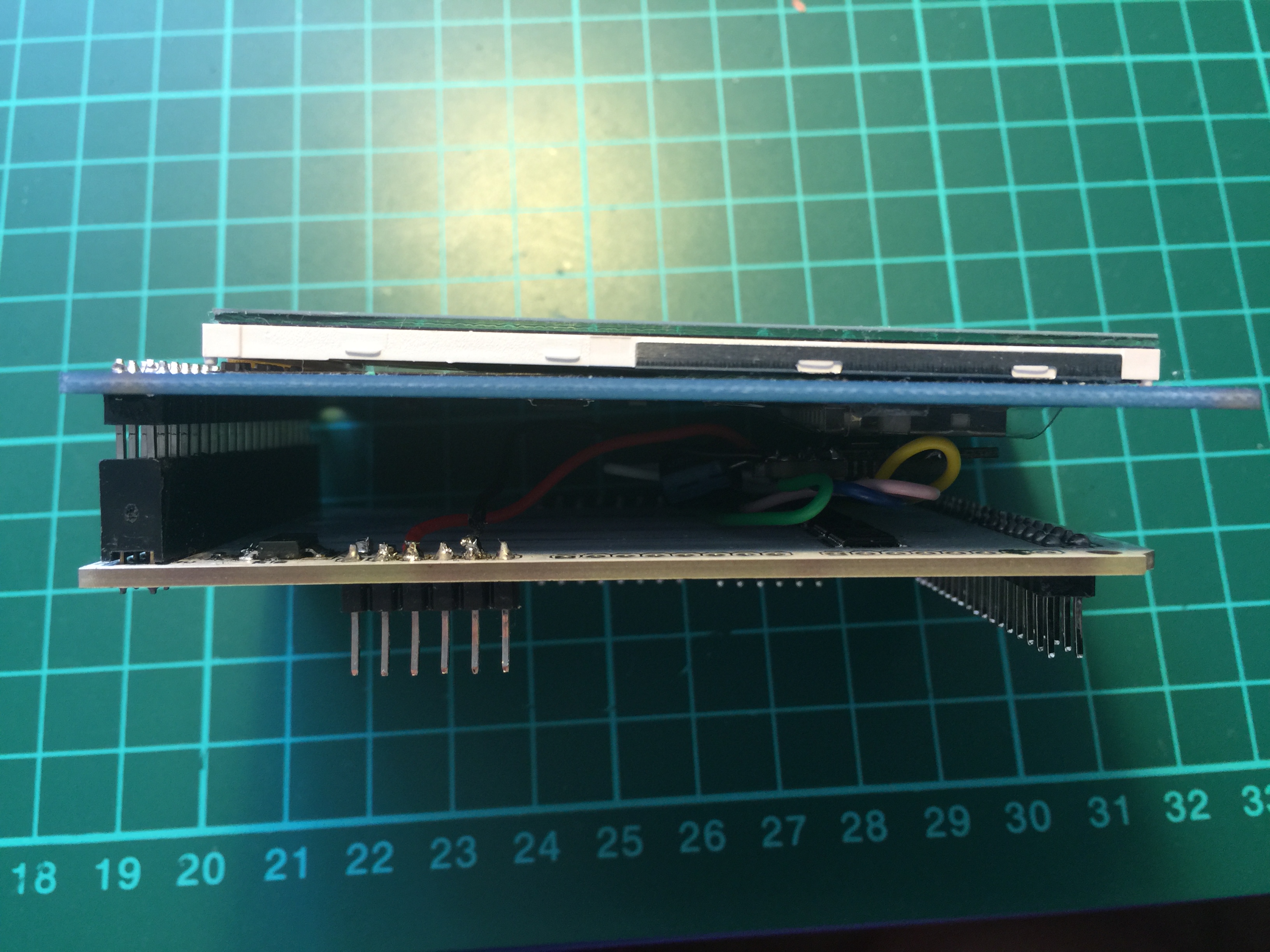
This is a semi finished project. The power is fed via ICSP through 662k (under the red tape):
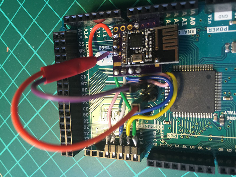
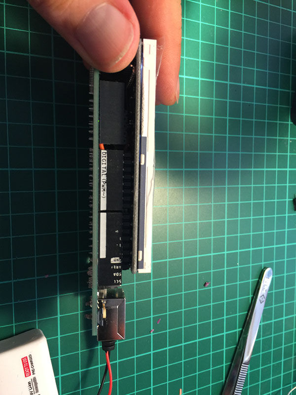
Now I need to isolate everything:
This is how Mega + the screen looks:
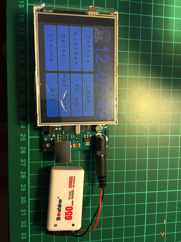
Now I need to figure out how to stick the battery between the screen and Mega :)
Any suggestions welcome! -
This is a semi finished project. The power is fed via ICSP through 662k (under the red tape):
Now I need to isolate everything:
This is how Mega + the screen looks:
Now I need to figure out how to stick the battery between the screen and Mega :)
Any suggestions welcome! -
@alexsh1
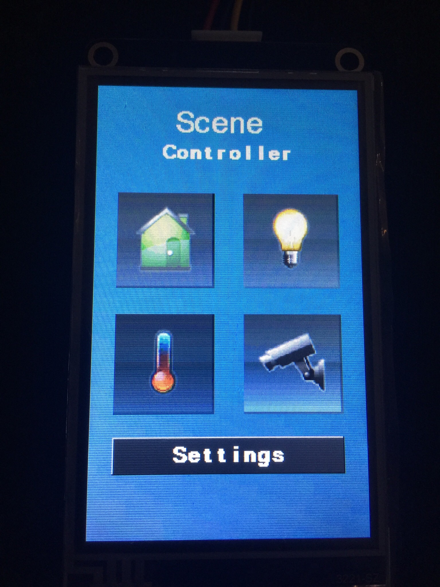
cool ;) I made one like this some time ago https://forum.mysensors.org/topic/2766/an-esp8266-nextion-scene-controller/5
but it's not with the new nextion rev. i like these hmi screens, easy to use. -
@alexsh1
cool ;) I made one like this some time ago https://forum.mysensors.org/topic/2766/an-esp8266-nextion-scene-controller/5
but it's not with the new nextion rev. i like these hmi screens, easy to use.@scalz Yeah, I saw your post a few months ago and it made me think seriously about getting my hands dirty with ESP8266. I have just started so do not expect to come up with anything fully working tomorrow as there are many peculiarities concerning ESP8266 from firmware to programming.
You have fully finished integration of your thermostat/scene controller with the controller?
Are you using Domoticz? -
@alexsh1 i'm using mqtt and jeedom for this (jeedom has plugin for thermostat etc..) and i have another board which does energy monitoring+heater management. just for curiosity, i have enough pcb lol, but where did you buy your pcb for nextion? or maybe you did it?
-
@alexsh1 i'm using mqtt and jeedom for this (jeedom has plugin for thermostat etc..) and i have another board which does energy monitoring+heater management. just for curiosity, i have enough pcb lol, but where did you buy your pcb for nextion? or maybe you did it?
@scalz I am not that smart yet to design my own boards. Having said that I have made a good progress on C++ and MySensors over a year. So designing my own PCB is a next logical step.
The problem is that my home has been fully automated. I have to challenge myself with a more difficult projects or move on to automate my neighbours house lol :-)
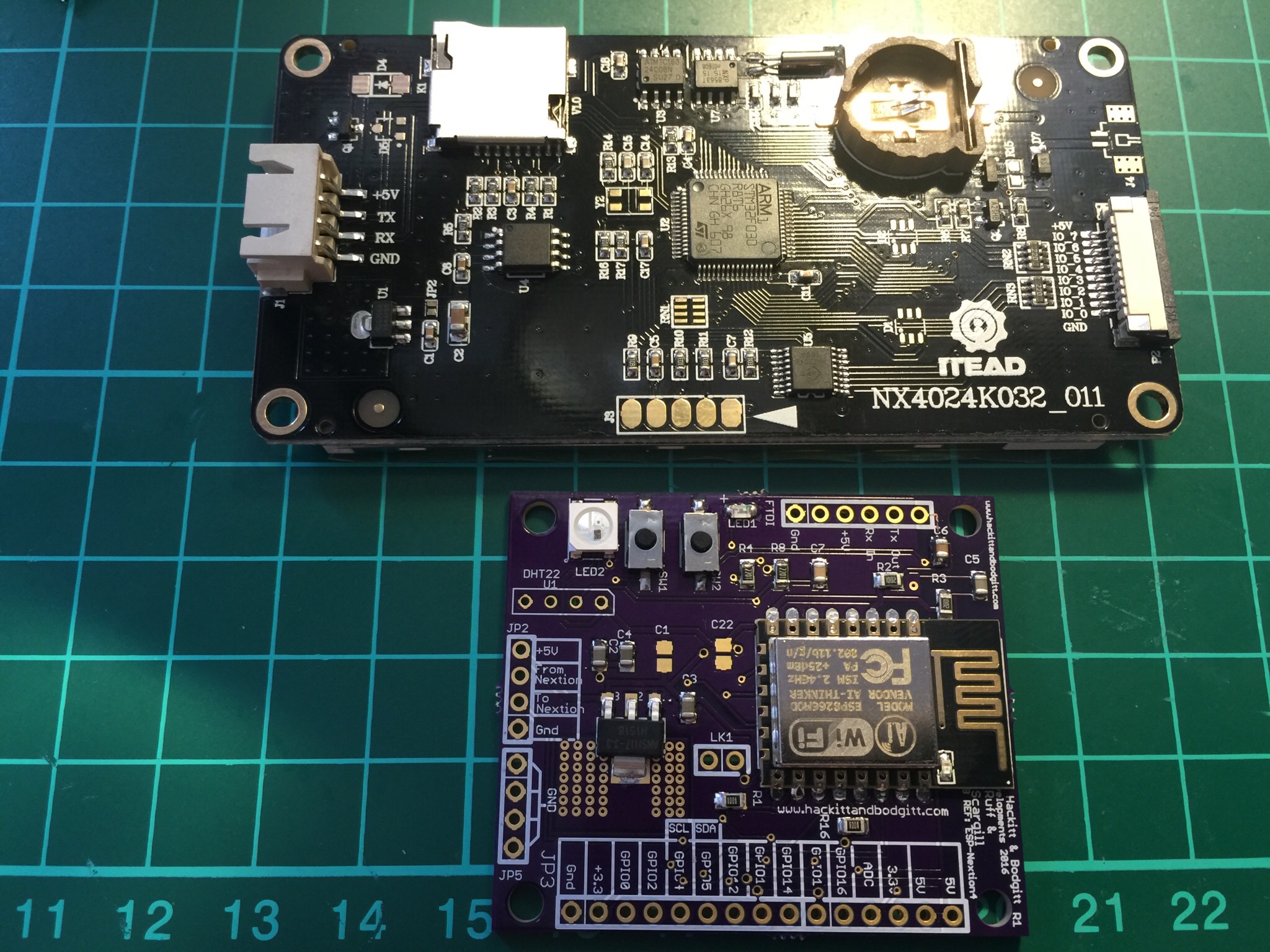
The most difficult part though is finding the right case. Printing on 3D printer is not cheap as I do not have one and finding something of the shelf is literally impossible.Talking about the PCB, I took the one design by
Peter and Aidan:http://tech.scargill.net/new-pcb/
However, I'm redesigning the software part to make it a multi functioning scene controller for Domoticz.