💬 Battery Powered Sensors
-
@sineverba thanks, I got it working and it's up and running. Still have to desolder the led and remove the regulator, will do that later.
Regarding the BOD, what happens if I disable it? Will it run for longer as it does not shutdown? Or is any voltage below 1.8v bad for the arduino?A bit off topic maybe, but I was wondering how the 'pros' around here make the sensor small and sturdy for Arduino's with Si7021+ 2xAA battery pack. My DuPont wires seem a bit loose, so I'm wondering whether I should solder them. And perhaps someone 3d printed a case for an Arduino+Batterypack or some sorts.
@Sebex said in 💬 Battery Powered Sensors:
Regarding the BOD, what happens if I disable it? Will it run for longer as it does not shutdown? Or is any voltage below 1.8v bad for the arduino?
1.8V is the minimum voltage according to the atmega328 datasheet. Below that it might work, but it might also do all sorts of strange things. We've seen reports of nodes getting stuck on continuous transmit, blasting radio signals all the time which blocks all other nodes from communicating. So keeping the bod at 1.8V is probably a good idea. 2xAA have almost no power left at 1.8V anyway. See https://www.avrfreaks.net/forum/aa-alkaline-discharge-curve-5ma for some discharge curves.
-
@Sebex said in 💬 Battery Powered Sensors:
Regarding the BOD, what happens if I disable it? Will it run for longer as it does not shutdown? Or is any voltage below 1.8v bad for the arduino?
1.8V is the minimum voltage according to the atmega328 datasheet. Below that it might work, but it might also do all sorts of strange things. We've seen reports of nodes getting stuck on continuous transmit, blasting radio signals all the time which blocks all other nodes from communicating. So keeping the bod at 1.8V is probably a good idea. 2xAA have almost no power left at 1.8V anyway. See https://www.avrfreaks.net/forum/aa-alkaline-discharge-curve-5ma for some discharge curves.
@mfalkvidd thanks makes sense, eventually I will switch to NiMh. Had a look at the different cases, gives some good inspiration thanks for pointing in the right direction!
Now that I want to desolder the regulator and LED on the Nano, I just want to verify something, since the video shown is about the mini pro.
(1) Is the circled part in the image below, indeed the regulator on the Nano?
(2) On the battery powered sensor page, step 4 states to cutout the Vout pin. Why does this lower power consumption, and how can I locate this on the Nano? -
@mfalkvidd thanks makes sense, eventually I will switch to NiMh. Had a look at the different cases, gives some good inspiration thanks for pointing in the right direction!
Now that I want to desolder the regulator and LED on the Nano, I just want to verify something, since the video shown is about the mini pro.
(1) Is the circled part in the image below, indeed the regulator on the Nano?
(2) On the battery powered sensor page, step 4 states to cutout the Vout pin. Why does this lower power consumption, and how can I locate this on the Nano?@Sebex I have never tried to run a Nano on battery, so I don't know but that looks like a regulator.
The Nano operates at 5V and consumes much more power than a 3.3V Pro Mini.
Yes, the regulator will consume power if it is not disconnected.
-
@Sebex I have never tried to run a Nano on battery, so I don't know but that looks like a regulator.
The Nano operates at 5V and consumes much more power than a 3.3V Pro Mini.
Yes, the regulator will consume power if it is not disconnected.
The big chip to the left is also a serial-usb converter which needs to be removed, making it not possible to program from the usb socket. Along with these components there are resistors and other components that might blead current so i dont think its that easy compared to just doing it to a Pro Mini.
Controller: Proxmox VM - Home Assistant
MySensors GW: Arduino Uno - W5100 Ethernet, Gw Shield Nrf24l01+ 2,4Ghz
MySensors GW: Arduino Uno - Gw Shield RFM69, 433mhz
RFLink GW - Arduino Mega + RFLink Shield, 433mhz -
The big chip to the left is also a serial-usb converter which needs to be removed, making it not possible to program from the usb socket. Along with these components there are resistors and other components that might blead current so i dont think its that easy compared to just doing it to a Pro Mini.
-
@Sebex - i think thats the easiest way, but sometimes its fun to try to create something new - its not impossible, but I would try to reverse engineer the nano (already done - search arduino nano schematic) and there you have to identify all "not essential" components and remove those (ie, making it a big pro-mini) to be able to get the current down as much as possible.
-
@sineverba thanks, I got it working and it's up and running. Still have to desolder the led and remove the regulator, will do that later.
Regarding the BOD, what happens if I disable it? Will it run for longer as it does not shutdown? Or is any voltage below 1.8v bad for the arduino?A bit off topic maybe, but I was wondering how the 'pros' around here make the sensor small and sturdy for Arduino's with Si7021+ 2xAA battery pack. My DuPont wires seem a bit loose, so I'm wondering whether I should solder them. And perhaps someone 3d printed a case for an Arduino+Batterypack or some sorts.
@Sebex said in 💬 Battery Powered Sensors:
A bit off topic maybe, but I was wondering how the 'pros' around here make the sensor small and sturdy for Arduino's with Si7021+ 2xAA battery pack. My DuPont wires seem a bit loose, so I'm wondering whether I should solder them. And perhaps someone 3d printed a case for an Arduino+Batterypack or some sorts.
You may want to try wire wrapping. It’s faster than soldering, sturdier than DuPont and you can connect multiple wires on same pin. Works wonders for gnd and vcc. Of course if the project is yanked harder, the wire wraps come out.
I made this small video for my home automation group in India. - hence prices for the wire wraps and tool are mentioned in local currency. I leant about this amazing technique from Andreas Spiess
my video
guy with Swiss accent -
@Puneit-Thukral Both DuPont and wirewrap are generally considered as prototyping methods. For final device build and production more secure connections should be implemented.
@skywatch Agree with every word of yours. Not justifying myself here but wirewraps are deployed all over my house. I pour some hot glue to ensure that they don’t come loose. And then a 3D printed enclosure takes care of the elements.
Also, it helps me to quickly repurpose the hardware.
It’s just another approach.
In an ideal world - where PCB shipments never arrive from China and locally they are a but expensive , this is my poor man’s alternative.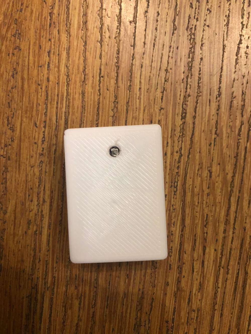
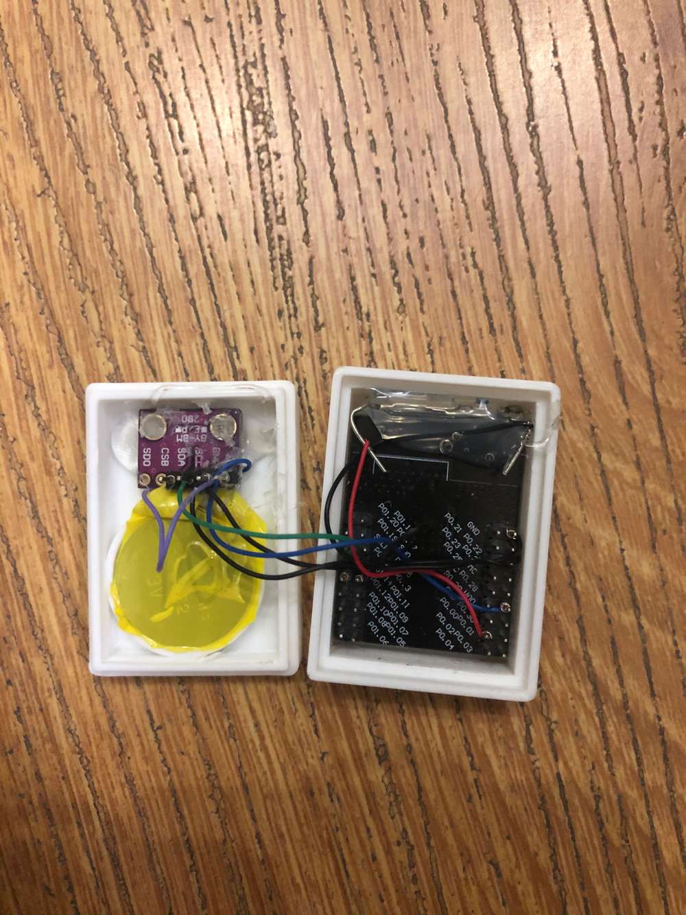 Example photos. The coin cell holder is diy. Used shaving blades and wrapped wires and taped to create a circuit.
 -
@skywatch Agree with every word of yours. Not justifying myself here but wirewraps are deployed all over my house. I pour some hot glue to ensure that they don’t come loose. And then a 3D printed enclosure takes care of the elements.
Also, it helps me to quickly repurpose the hardware.
It’s just another approach.
In an ideal world - where PCB shipments never arrive from China and locally they are a but expensive , this is my poor man’s alternative. Example photos. The coin cell holder is diy. Used shaving blades and wrapped wires and taped to create a circuit.@Puneit-Thukral I understand 'poor mans alternative' soooo well! ;)
Glue on the wirewraps will help keep them in place and mitigate thermal stress to some degree and also stop dust and moisture. But over time the glue will change and shrink/crack and things will start to become strange with that arrangement.
It's hard to beat a good soldered joint in the end, that's why all the commercial kit is done that way.
Nice case BTW. I also am working on 3D printed cases for some nodes. Another 6 weeks of lockdown and I should have started on them! ;)
-
@Sebex said in 💬 Battery Powered Sensors:
A bit off topic maybe, but I was wondering how the 'pros' around here make the sensor small and sturdy for Arduino's with Si7021+ 2xAA battery pack. My DuPont wires seem a bit loose, so I'm wondering whether I should solder them. And perhaps someone 3d printed a case for an Arduino+Batterypack or some sorts.
You may want to try wire wrapping. It’s faster than soldering, sturdier than DuPont and you can connect multiple wires on same pin. Works wonders for gnd and vcc. Of course if the project is yanked harder, the wire wraps come out.
I made this small video for my home automation group in India. - hence prices for the wire wraps and tool are mentioned in local currency. I leant about this amazing technique from Andreas Spiess
my video
guy with Swiss accent -
@Puneit-Thukral interesting! Seems as a better option than Dupont, I'm gonna look into it.
You mention hot glueing the wires yourself as extra protection. But I imagine you can also put a layer of solder on it right? -
@Sebex yes, of course. I have done that as well. In case I need to repurpose something , removing solder completely away is a tougher job for me than peeling away a layer of glue. Guess, I am just lazy. 😃
@Puneit-Thukral haha okay I see.
Another question, your case that you use in the video snaps onto the pins perfectly it seems. Did you 3d print that yourself? I'm looking to 3D print a case for my pro mini and some other sensors that snaps in a similar way so that nothing moves around. However I'd rather copy a proven design than figuring out the tolerances myself.
-
@Puneit-Thukral haha okay I see.
Another question, your case that you use in the video snaps onto the pins perfectly it seems. Did you 3d print that yourself? I'm looking to 3D print a case for my pro mini and some other sensors that snaps in a similar way so that nothing moves around. However I'd rather copy a proven design than figuring out the tolerances myself.
@Sebex Yes, I 3D printed on my ender 3 and I am using this on nodemcu running ESPhome. But I did not design it. Here is the Thingiverse link to it.
Nodemcu caseI would love to do similar case and a larger case like this to fit other boards. Its rock solid. I do not have skills to make a linear pattern like this. I think I should figure out how to do it.
-
@Puneit-Thukral cool, from what I read the pins are the same size as on Arduino's. I'll use this design to create one for myself.
-
@Sebex Do share the STL - it will be great and if you use Fusion360, then may I request for the F3D file.. I am semi-skilled when it comes to designing
@Puneit-Thukral Will do!
After closer inspection the pins of the NodeMCU seem to be a lot bigger in size. However I am struggling to find the correct sizing of Arduino Pro Mini pins (width/thickness). The spacing between pins and length of them are easy to find but I cannot find the thickness at all. Do you have an idea? -
@Puneit-Thukral Will do!
After closer inspection the pins of the NodeMCU seem to be a lot bigger in size. However I am struggling to find the correct sizing of Arduino Pro Mini pins (width/thickness). The spacing between pins and length of them are easy to find but I cannot find the thickness at all. Do you have an idea?@Sebex Will this help
https://grabcad.com/library/arduino-pro-mini-1
and should we move this conversation to another topic /PM as this is not relevant to this thread. -
@mfalkvidd, on the image I see the following marking in red

VCC ==> N/C
Do you know what the meaning is?
This VCC pin and the other VCC pin at the bottom of the image are connected. I verified with the multimeter.
So, what's the purpose of this remark?These pins at the right are used to program the pro mini. I had no problems to program after removing the led and the power regulator. The programmer used the VCC to power the pro mini without any problem...
-
@mfalkvidd, on the image I see the following marking in red
VCC ==> N/C
Do you know what the meaning is?
This VCC pin and the other VCC pin at the bottom of the image are connected. I verified with the multimeter.
So, what's the purpose of this remark?These pins at the right are used to program the pro mini. I had no problems to program after removing the led and the power regulator. The programmer used the VCC to power the pro mini without any problem...
@evb I believe that the reason is to physically (and electrically) isolate the voltage regulator from the circuit. Then only VCC will work and not RAW.
Essentially the same as removing the led or it's series resistor (only one or the other will do) and the regulator from the board.