💬 Battery Powered Sensors
-
@Puneit-Thukral interesting! Seems as a better option than Dupont, I'm gonna look into it.
You mention hot glueing the wires yourself as extra protection. But I imagine you can also put a layer of solder on it right? -
@Sebex yes, of course. I have done that as well. In case I need to repurpose something , removing solder completely away is a tougher job for me than peeling away a layer of glue. Guess, I am just lazy. 😃
@Puneit-Thukral haha okay I see.
Another question, your case that you use in the video snaps onto the pins perfectly it seems. Did you 3d print that yourself? I'm looking to 3D print a case for my pro mini and some other sensors that snaps in a similar way so that nothing moves around. However I'd rather copy a proven design than figuring out the tolerances myself.
-
@Puneit-Thukral haha okay I see.
Another question, your case that you use in the video snaps onto the pins perfectly it seems. Did you 3d print that yourself? I'm looking to 3D print a case for my pro mini and some other sensors that snaps in a similar way so that nothing moves around. However I'd rather copy a proven design than figuring out the tolerances myself.
@Sebex Yes, I 3D printed on my ender 3 and I am using this on nodemcu running ESPhome. But I did not design it. Here is the Thingiverse link to it.
Nodemcu caseI would love to do similar case and a larger case like this to fit other boards. Its rock solid. I do not have skills to make a linear pattern like this. I think I should figure out how to do it.
-
@Puneit-Thukral cool, from what I read the pins are the same size as on Arduino's. I'll use this design to create one for myself.
-
@Sebex Do share the STL - it will be great and if you use Fusion360, then may I request for the F3D file.. I am semi-skilled when it comes to designing
@Puneit-Thukral Will do!
After closer inspection the pins of the NodeMCU seem to be a lot bigger in size. However I am struggling to find the correct sizing of Arduino Pro Mini pins (width/thickness). The spacing between pins and length of them are easy to find but I cannot find the thickness at all. Do you have an idea? -
@Puneit-Thukral Will do!
After closer inspection the pins of the NodeMCU seem to be a lot bigger in size. However I am struggling to find the correct sizing of Arduino Pro Mini pins (width/thickness). The spacing between pins and length of them are easy to find but I cannot find the thickness at all. Do you have an idea?@Sebex Will this help
https://grabcad.com/library/arduino-pro-mini-1
and should we move this conversation to another topic /PM as this is not relevant to this thread. -
@mfalkvidd, on the image I see the following marking in red

VCC ==> N/C
Do you know what the meaning is?
This VCC pin and the other VCC pin at the bottom of the image are connected. I verified with the multimeter.
So, what's the purpose of this remark?These pins at the right are used to program the pro mini. I had no problems to program after removing the led and the power regulator. The programmer used the VCC to power the pro mini without any problem...
-
@mfalkvidd, on the image I see the following marking in red
VCC ==> N/C
Do you know what the meaning is?
This VCC pin and the other VCC pin at the bottom of the image are connected. I verified with the multimeter.
So, what's the purpose of this remark?These pins at the right are used to program the pro mini. I had no problems to program after removing the led and the power regulator. The programmer used the VCC to power the pro mini without any problem...
@evb I believe that the reason is to physically (and electrically) isolate the voltage regulator from the circuit. Then only VCC will work and not RAW.
Essentially the same as removing the led or it's series resistor (only one or the other will do) and the regulator from the board.
-
@evb I believe that the reason is to physically (and electrically) isolate the voltage regulator from the circuit. Then only VCC will work and not RAW.
Essentially the same as removing the led or it's series resistor (only one or the other will do) and the regulator from the board.
@skywatch, you mean that in normal conditions with the power regulator, we connect the power supply (max 16VDC) to the raw pin and can take 3.3V or 5V, depending on which version, at the pin VCC?
And that now it isn't possible anymore with the regulator removed?I would propose to change the picture :
- there are 2 VCC pins, so the current picture is confusing
- adapt the drawing and mention to connect the battery (2xAA) 3V directly to VCC pin at the bottom (not the VCC pin in the programming row of contacts!)
@skywatch and @mfalkvidd, what do you think?
-
@skywatch, you mean that in normal conditions with the power regulator, we connect the power supply (max 16VDC) to the raw pin and can take 3.3V or 5V, depending on which version, at the pin VCC?
And that now it isn't possible anymore with the regulator removed?I would propose to change the picture :
- there are 2 VCC pins, so the current picture is confusing
- adapt the drawing and mention to connect the battery (2xAA) 3V directly to VCC pin at the bottom (not the VCC pin in the programming row of contacts!)
@skywatch and @mfalkvidd, what do you think?
@evb said in 💬 Battery Powered Sensors:
@skywatch, you mean that in normal conditions with the power regulator, we connect the power supply (max 16VDC) to the raw pin and can take 3.3V or 5V, depending on which version, at the pin VCC?
And that now it isn't possible anymore with the regulator removed?Yes, because the regulator will drain batteries faster using raw than connecting an appropriate voltage to VCC....
I would propose to change the picture :
- there are 2 VCC pins, so the current picture is confusing
- adapt the drawing and mention to connect the battery (2xAA) 3V directly to VCC pin at the bottom (not the VCC pin in the programming row of contacts!)
@skywatch and @mfalkvidd, what do you think?
I think it is up to the user to decide what pins they want to connect to and why.
-
@skywatch, you mean that in normal conditions with the power regulator, we connect the power supply (max 16VDC) to the raw pin and can take 3.3V or 5V, depending on which version, at the pin VCC?
And that now it isn't possible anymore with the regulator removed?I would propose to change the picture :
- there are 2 VCC pins, so the current picture is confusing
- adapt the drawing and mention to connect the battery (2xAA) 3V directly to VCC pin at the bottom (not the VCC pin in the programming row of contacts!)
@skywatch and @mfalkvidd, what do you think?
@evb I don't know what the N/C text means. Presumably N/C stands for Not Connected, but I don't understand what isn't (or shouldn't?) be connected, so I can't say anything about that part unfortunately.
The device can be powered through any of the two Vcc pins. Use the one that is most convenient.
I am not aware of any Arduinos that can handle 16V input on the raw pin. Most clones don't even handle 12V.
If the regulator is removed, the Arduino can no longer be powered through the raw pin.
-
@evb I don't know what the N/C text means. Presumably N/C stands for Not Connected, but I don't understand what isn't (or shouldn't?) be connected, so I can't say anything about that part unfortunately.
The device can be powered through any of the two Vcc pins. Use the one that is most convenient.
I am not aware of any Arduinos that can handle 16V input on the raw pin. Most clones don't even handle 12V.
If the regulator is removed, the Arduino can no longer be powered through the raw pin.
@mfalkvidd That's why I propose to adapt the article and image :-)
If even experienced people like you don't know what it means, what should beginners think?
I was confused and did some extra research on schematics, etc on the internet and measurements on my pro mini, afraid to blow up my only TTL to USB programmer after the modification of the pro mini for saving power consumption :sweat:The 16V was found on a schematics from the arduino.cc (https://www.arduino.cc/en/uploads/Main/Arduino-Pro-Mini-schematic.pdf). I use typically a 9V power adapter to be safe.
@skywatch You are right that the user finally decides what VCC pins he or she will connect, but we can help him and give a hint : if he uses the right VCC pin to solder his battery wire, he will have a hard time to connect his TTL to USB programmer...
-
@mfalkvidd That's why I propose to adapt the article and image :-)
If even experienced people like you don't know what it means, what should beginners think?
I was confused and did some extra research on schematics, etc on the internet and measurements on my pro mini, afraid to blow up my only TTL to USB programmer after the modification of the pro mini for saving power consumption :sweat:The 16V was found on a schematics from the arduino.cc (https://www.arduino.cc/en/uploads/Main/Arduino-Pro-Mini-schematic.pdf). I use typically a 9V power adapter to be safe.
@skywatch You are right that the user finally decides what VCC pins he or she will connect, but we can help him and give a hint : if he uses the right VCC pin to solder his battery wire, he will have a hard time to connect his TTL to USB programmer...
@evb yes I see your point. But changing things without understanding the background is troublesome, in my experience. Whoever created the original image probably had a good reason to write the N/C part. Therefore, I would prefer if any of the "Ancients" (i.e. people who joined the project before me) could chip in.
-
@mfalkvidd That's why I propose to adapt the article and image :-)
If even experienced people like you don't know what it means, what should beginners think?
I was confused and did some extra research on schematics, etc on the internet and measurements on my pro mini, afraid to blow up my only TTL to USB programmer after the modification of the pro mini for saving power consumption :sweat:The 16V was found on a schematics from the arduino.cc (https://www.arduino.cc/en/uploads/Main/Arduino-Pro-Mini-schematic.pdf). I use typically a 9V power adapter to be safe.
@skywatch You are right that the user finally decides what VCC pins he or she will connect, but we can help him and give a hint : if he uses the right VCC pin to solder his battery wire, he will have a hard time to connect his TTL to USB programmer...
@evb MySensors is a a technical project that involves both hardware, software and firmare. It is not that easy for everyone to follow a single example and then get all that they want.
Think of it as a leanring curve. You already found something that is not the way you want it to be for your use. Many others will agree with that. Some want it a different way.
The main objective is to learn all you can (or need) to get your projects to where you want them. Some out there won't have a single battery node at all, some will be more advanced in battery power conservation than the case in this thread.
I flagged a faulty 'build' example more than 2 years ago, but it is still there and still wrong. But mine works as it should because I studied the data sheets and did it the right way. Change does not come quickly it seems.
You have to put time and a lot of effort into this unless you already work in such an area or have a degree in associated methodolgy.
-
@evb MySensors is a a technical project that involves both hardware, software and firmare. It is not that easy for everyone to follow a single example and then get all that they want.
Think of it as a leanring curve. You already found something that is not the way you want it to be for your use. Many others will agree with that. Some want it a different way.
The main objective is to learn all you can (or need) to get your projects to where you want them. Some out there won't have a single battery node at all, some will be more advanced in battery power conservation than the case in this thread.
I flagged a faulty 'build' example more than 2 years ago, but it is still there and still wrong. But mine works as it should because I studied the data sheets and did it the right way. Change does not come quickly it seems.
You have to put time and a lot of effort into this unless you already work in such an area or have a degree in associated methodolgy.
@skywatch unfortunately, that is also the impression I have, the documentation is not always up to date and it is a laborious process to get it improved. :-(
MySensors is a great project, but the learning curve is not negligible. Making it easier for beginners with real-world examples might make that learning curve a bit easier.
I've already mentioned it, but one example is the workflow of the open source project Home Assistant. The setup of the documentation and the possible pull requests for improvement are easier to get accepted.
If @mfalkvidd now manages to find and to wake up the 'Ancients', this article might be able to be improved anyway :grinning: :+1:
-
@evb yes I see your point. But changing things without understanding the background is troublesome, in my experience. Whoever created the original image probably had a good reason to write the N/C part. Therefore, I would prefer if any of the "Ancients" (i.e. people who joined the project before me) could chip in.
@mfalkvidd Don't know if I'm qualified, but I've vague memory (or a wild guess). I think there were some pro-mini models that lost connection to one vcc-pin if you made the cut after the voltage regulator. And btw I never really know why the cutting method was so popular.
-
@mfalkvidd Don't know if I'm qualified, but I've vague memory (or a wild guess). I think there were some pro-mini models that lost connection to one vcc-pin if you made the cut after the voltage regulator. And btw I never really know why the cutting method was so popular.
@m26872, your memory is correct. There are or were pro-mini models who lost connection on the VCC pin at the right if you removed the power regulator. (https://forum.pimatic.org/topic/383/tips-battery-powered-sensors/2).
My batch of chinese pro mini's are not loosing their connection with the VCC pin at the right.
@mfalkvidd, you can maybe adapt the wiki article with this extra info?
-
Meanwhile I found following forum topic : https://forum.mysensors.org/topic/2067/my-slim-2aa-battery-node. Thanks @m26872 :-)
@mfalkvidd, I insist ;-) , if modifying these 'official' site articles turns out to be so difficult, can't a new section not be added like for example 'User experiences' or 'Advanced use' or 'Real world examples' or ... ?
Now we are obliged to read through hours of forum topics, hoping to find more information somewhere.
On one hand, this is of course instructive, but on the other hand it also wastes a lot of time looking for answers.
If we already had a starting list of some topics from experienced users, the learning curve would already be smaller.I started my battery crusade months ago by ordering some Arduino Pro Mini's from our Chinese supplier AliExpress following the official site article.
Because I could not obtain the given consumption of current, I began to search further.
Today after hours of searching and reading on the forum, I realize that this choice was actually not the right one.
I probably had better ordered the custom PCB from @m26872 and used a barebone 328P, or a Moteino or a Canique or...As far as the current of my pro mini is concerned, I'm stuck at a minimum of 133µA.
- pro mini without power led and power regulator
- refused using the MiniCore packet to 1.8V BOD and 1MHz internal
- board : ATmega328
- clock : internal 1 MHz
- BOD : BOD 1.8V
- EEPROM : EEPROM retained
- Variant : 328P / 328PA
- Bootloader : Yes (UART0)
- only one open or closed contact on pin D3 with external pull-up of 1M ohm
- radio is a RFM69HW
- sketch is using the mysensors sleep function with interrupt wake up (MySensors lib version 2.3.2).
To test if it was the radio module not completely sleeping and causing this consumption, I tested the same on a other pro mini (no power led and no power regulator, same refusing), without any external hardware, using the LowPower sketch from https://andreasrohner.at/posts/Electronics/How-to-modify-an-Arduino-Pro-Mini-clone-for-low-power-consumption/
==>same measurement : 133µA
So the radio module is not the raison!So what is the cause of this higher consumption?
The quality of the Chinese clone boards?
Or is there still external hardware on the board consuming some current? The external crystal still present for example?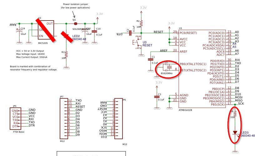
On the pro mini, there is a led connected to the SCK pin. I think that will add an extra of +-1mA when the radio is active?
But it has nothing to do with the sleep current of 133µA... -
Meanwhile I found following forum topic : https://forum.mysensors.org/topic/2067/my-slim-2aa-battery-node. Thanks @m26872 :-)
@mfalkvidd, I insist ;-) , if modifying these 'official' site articles turns out to be so difficult, can't a new section not be added like for example 'User experiences' or 'Advanced use' or 'Real world examples' or ... ?
Now we are obliged to read through hours of forum topics, hoping to find more information somewhere.
On one hand, this is of course instructive, but on the other hand it also wastes a lot of time looking for answers.
If we already had a starting list of some topics from experienced users, the learning curve would already be smaller.I started my battery crusade months ago by ordering some Arduino Pro Mini's from our Chinese supplier AliExpress following the official site article.
Because I could not obtain the given consumption of current, I began to search further.
Today after hours of searching and reading on the forum, I realize that this choice was actually not the right one.
I probably had better ordered the custom PCB from @m26872 and used a barebone 328P, or a Moteino or a Canique or...As far as the current of my pro mini is concerned, I'm stuck at a minimum of 133µA.
- pro mini without power led and power regulator
- refused using the MiniCore packet to 1.8V BOD and 1MHz internal
- board : ATmega328
- clock : internal 1 MHz
- BOD : BOD 1.8V
- EEPROM : EEPROM retained
- Variant : 328P / 328PA
- Bootloader : Yes (UART0)
- only one open or closed contact on pin D3 with external pull-up of 1M ohm
- radio is a RFM69HW
- sketch is using the mysensors sleep function with interrupt wake up (MySensors lib version 2.3.2).
To test if it was the radio module not completely sleeping and causing this consumption, I tested the same on a other pro mini (no power led and no power regulator, same refusing), without any external hardware, using the LowPower sketch from https://andreasrohner.at/posts/Electronics/How-to-modify-an-Arduino-Pro-Mini-clone-for-low-power-consumption/
==>same measurement : 133µA
So the radio module is not the raison!So what is the cause of this higher consumption?
The quality of the Chinese clone boards?
Or is there still external hardware on the board consuming some current? The external crystal still present for example?On the pro mini, there is a led connected to the SCK pin. I think that will add an extra of +-1mA when the radio is active?
But it has nothing to do with the sleep current of 133µA...@evb sorry for the late reply. I noticed your post earlier, but quickly realized I would need some time to catch up and grasp the full discussion. Now, when I finally have time to try to catch up, I realize that this is way beyond my capability of understanding. But if you provide instructions, I can paste them into the pages you deem relevant.