💬 Battery Powered Sensors
-
Does enabled myDebug and some Serial.print statements (with serial port disconnected) affect power consumption of the node?
-
Does enabled myDebug and some Serial.print statements (with serial port disconnected) affect power consumption of the node?
-
If I remember correctly, writing to the serial port takes about 10s / baud rate for a single byte. That's a little unter 90µs at 115200 baud (common for Arduinos clocking 16 MHz at 5V) or about 1ms at 9600 baud (1MHz for 3V or less).
Imagine we are transmitting two messages per wake cycle and print another few custom lines to the serial port as well, that may result in about 500 bytes total. This would then add another 45ms on a fast clocking Arduino (115200 baud) or 0.5s (9600 baud) - plus likely some overhead - to the time the microcontroller spends in an active state.
According to the datasheet (p.312), an ATmega328P clocking at 1MHz consumes about 0.5mA in an active state at about 3V. So, from here on, you could calculate how drastically (or not) an additional ~0.1 - 0.7s of active time per wake cycle would impact the runtime of the battery.
Since it's possible to run a node for a year or much longer off a set of batteries if it doesn't send lots of messages every few minutes, I doubt you would be able to notice a difference between disabling debug prints or keeping them.
It is usually much more important to keep the current consumption during the power down phase as low as possible, than shedding off a few ms of active time.
-
@evb Hello. I am the maker of the Canique MK2 boards. I started just like you with the website from Andreas Rohner, desoldering the LED and desoldering the voltage regulator from such a chinese board until I realized this is the wrong way round.
As far as I recall, I've seen voltage regulators consume something in the order of 100uA when reverse powered. So that might be a hint.
The external crystal should not be drawing that much current. Using a 16MHz oscillator current can go as low as 4uA with watchdog enabled - in theory and on boards built with minimum consumption as a design goal.To your question regarding the SCK pin: yes, if it is connected to a LED every clock pulse on the SCK pin (when SPI is enabled) will make the LED draw current.
You also have these kinds of troubles (SPI drawing too much current when active or inactive) with chinese boards having a BME280 on them for example. If you have high quality standards, the stock chinese boards won't fit your needs.
-
Meanwhile I found following forum topic : https://forum.mysensors.org/topic/2067/my-slim-2aa-battery-node. Thanks @m26872 :-)
@mfalkvidd, I insist ;-) , if modifying these 'official' site articles turns out to be so difficult, can't a new section not be added like for example 'User experiences' or 'Advanced use' or 'Real world examples' or ... ?
Now we are obliged to read through hours of forum topics, hoping to find more information somewhere.
On one hand, this is of course instructive, but on the other hand it also wastes a lot of time looking for answers.
If we already had a starting list of some topics from experienced users, the learning curve would already be smaller.I started my battery crusade months ago by ordering some Arduino Pro Mini's from our Chinese supplier AliExpress following the official site article.
Because I could not obtain the given consumption of current, I began to search further.
Today after hours of searching and reading on the forum, I realize that this choice was actually not the right one.
I probably had better ordered the custom PCB from @m26872 and used a barebone 328P, or a Moteino or a Canique or...As far as the current of my pro mini is concerned, I'm stuck at a minimum of 133µA.
- pro mini without power led and power regulator
- refused using the MiniCore packet to 1.8V BOD and 1MHz internal
- board : ATmega328
- clock : internal 1 MHz
- BOD : BOD 1.8V
- EEPROM : EEPROM retained
- Variant : 328P / 328PA
- Bootloader : Yes (UART0)
- only one open or closed contact on pin D3 with external pull-up of 1M ohm
- radio is a RFM69HW
- sketch is using the mysensors sleep function with interrupt wake up (MySensors lib version 2.3.2).
To test if it was the radio module not completely sleeping and causing this consumption, I tested the same on a other pro mini (no power led and no power regulator, same refusing), without any external hardware, using the LowPower sketch from https://andreasrohner.at/posts/Electronics/How-to-modify-an-Arduino-Pro-Mini-clone-for-low-power-consumption/
==>same measurement : 133µA
So the radio module is not the raison!So what is the cause of this higher consumption?
The quality of the Chinese clone boards?
Or is there still external hardware on the board consuming some current? The external crystal still present for example?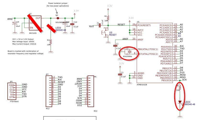
On the pro mini, there is a led connected to the SCK pin. I think that will add an extra of +-1mA when the radio is active?
But it has nothing to do with the sleep current of 133µA...@evb little info regarding the LED on the SCK pin.
Assuming it is a red LED with a forward voltage of 1.8V, considering the chip is powered with 3.3V and considering the 330 Ohm resistor in series with the LED, the additional current draw when SCK goes high should be about 4.5mA. -
@canique you confirm my suspicions. For the moment I have 3 working battery nodes with the pro mini and the RFM69HW. We will see how long the batteries are going to last. Normally it should be one year.
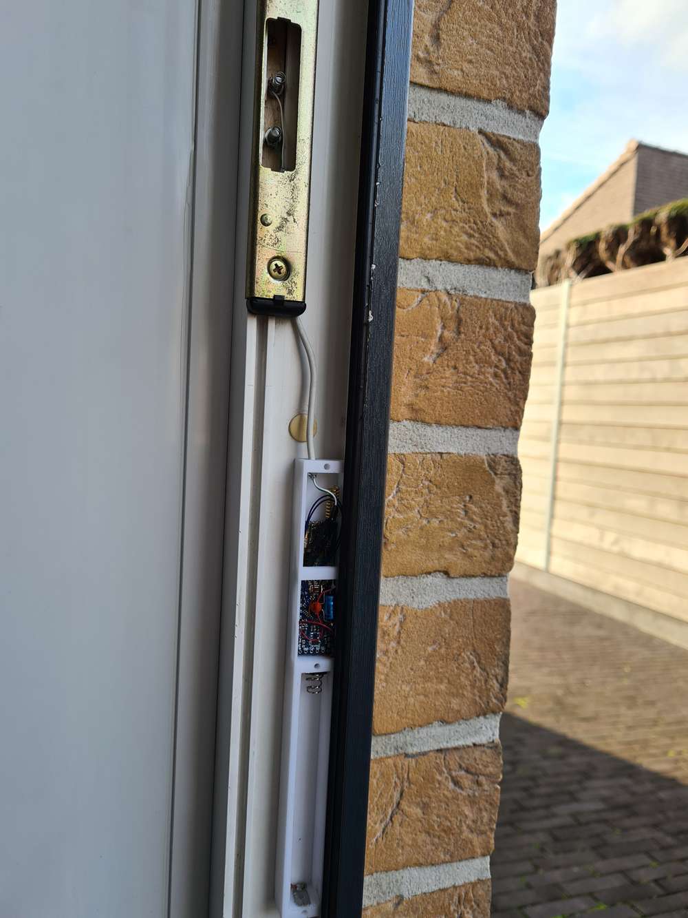
I'm constrained by the maximum dimensions of the sensor node. The case must go inside the PVC door frame, so it can be maximum 20mm width on 17mm height, the length is not a constraint. :-)
I had to solder the RFM69HW in line with the pro mini.
The MK2 boards are unfortunately too wide. -
@canique you confirm my suspicions. For the moment I have 3 working battery nodes with the pro mini and the RFM69HW. We will see how long the batteries are going to last. Normally it should be one year.
I'm constrained by the maximum dimensions of the sensor node. The case must go inside the PVC door frame, so it can be maximum 20mm width on 17mm height, the length is not a constraint. :-)
I had to solder the RFM69HW in line with the pro mini.
The MK2 boards are unfortunately too wide.@evb I can't see it clearly on the picture but this seems like a reed sensor to me.
Well, usually the transmitter does not have to be at some specific location. There are reed sensors based on magnets (connected with 2 wires to the transmitter). As soon as the magnets are close to each other, a small current flows (or vice versa). They are just attached to the window/door with some sticky adhesive. The transmitter can well be a meter away.I can say from experience with Atmega328P, that when drawing ~24uA in sleep and sending every 30 seconds a single battery lasts ~ 1 year.
This can all be calculated (rough estimates).
A basic online calculator for this kind of stuff can be found @ https://oregonembedded.com/batterycalc.htm -
@evb how's the range of your node? Being enclosed in aluminum will definitely reduce range.
@Yveaux It is not a aluminium door frame, but a PVC door frame (plastic).
The problem is that my gateway is in the extension of the brick wall, about 15m away in the garage at the backyard. So I have a 5m brick wall between de node and the gateway :-(
This means that the reliability of the connection is not good, so I had to place a repeater node between them. -
@evb I can't see it clearly on the picture but this seems like a reed sensor to me.
Well, usually the transmitter does not have to be at some specific location. There are reed sensors based on magnets (connected with 2 wires to the transmitter). As soon as the magnets are close to each other, a small current flows (or vice versa). They are just attached to the window/door with some sticky adhesive. The transmitter can well be a meter away.I can say from experience with Atmega328P, that when drawing ~24uA in sleep and sending every 30 seconds a single battery lasts ~ 1 year.
This can all be calculated (rough estimates).
A basic online calculator for this kind of stuff can be found @ https://oregonembedded.com/batterycalc.htm@canique no, the purpose of the node is to know when the door is locked by the bolt, not only closed. What you see are simply 2 battery springs and the bolt of the lock closes the contact.
I can move the node more upwards the door frame (and I will do it if the radio connection is still not reliable with the repeater).
In order to preserve domestic peace, I placed the nodes in the door frame, invisible when the door is closed: no visible dangling wires and no visible boxes.Maybe an idea for a MK3 version of your board as wide as the RFM69HW ;-)
-
Hello
I created battery powered node running on 2x 1.5V AA batteries with DC-DC step up booster. But the step up booster makes audible noise (very tiny beeping) when the radio is transmitting.
It is this step up booster https://www.laskarduino.cz/step-up-boost-menic-s-me2108-33v-480ma/
Is there any way to solve it?
Thanks
Tomas
@tssk There is a name for this noise: it is called "coil whine". In German "Spulenfiepen". It stems from the inductor - I wouldn't know any way to get rid of it.
My mainboard or power supply on my PC creates similar noise when the CPU goes in certain doze modes. -
Hello
I created battery powered node running on 2x 1.5V AA batteries with DC-DC step up booster. But the step up booster makes audible noise (very tiny beeping) when the radio is transmitting.
It is this step up booster https://www.laskarduino.cz/step-up-boost-menic-s-me2108-33v-480ma/
Is there any way to solve it?
Thanks
Tomas
@tssk I heard that people got rid of or at least reduced the coil whine by coating the windings of an audible inductor with non-conductive materials like epoxy resin or even hot glue to reduce the vibrations.
Of course, I woudn't mess with expensive PC hardware, but I guess there's not much to loose with a cheap boost module like this.
-
@tssk I heard that people got rid of or at least reduced the coil whine by coating the windings of an audible inductor with non-conductive materials like epoxy resin or even hot glue to reduce the vibrations.
Of course, I woudn't mess with expensive PC hardware, but I guess there's not much to loose with a cheap boost module like this.
Thanks all for the response.
@BearWithBeard I will start googling about such solution.
Do you think using different step up booster might help? Could someone recommend something?
-
I am biased since I run that website but I can recommend https://www.canique.com/boost
I've never heard it making noise. -
I am biased since I run that website but I can recommend https://www.canique.com/boost
I've never heard it making noise. -
@canique Thanks for the recommendation if I do not find fix for the model I am using I will consider buying it.
I will try to hot glue the side with the coil as I found on some pages. Any ideas / warnings? :)
@tssk Most of these boosters have a grounded backplane, perhaps trying to re-orientate the inductor so the backplane acts a shield to direct RF may be an option to try ?
If the noise in on the power line I've heard of some managing to block it with a VR circuit if the voltage drop is acceptable, but never tried it.