💬 Battery Powered Sensors
-
@tssk the led blinks because it is connected to the same pin as the SCK pin used by the nrf24.
@mfalkvidd You are right :) I did not know that.
SPI: 10 (SS), 11 (MOSI), 12 (MISO), 13 (SCK). These pins support SPI communication, which, although provided by the underlying hardware, is not currently included in the Arduino language.
LED: 13. There is a built-in LED connected to digital pin 13. When the pin is HIGH value, the LED is on, when the pin is LOW, it's off.https://www.arduino.cc/en/pmwiki.php?n=Main/ArduinoBoardProMini
Should I remove the LED to save power? Or it is marginal?
-
@mfalkvidd Thanks.
-
Hello
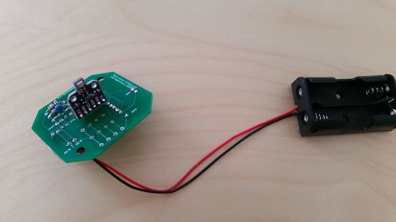
I would like to ask for help with passive battery powered node I created with following components:
- Arduino pro mini 8MHz - voltage regulator and power LED removed
- SX1276 based 868MHz LoRa radio
- BME680 sensor
- DC-DC 3.3V step-up booster
I created a battery measuring circuit according to scheme on this page ( https://www.mysensors.org/build/battery ).
The problem is the two fresh new AA batteries lasted less than 14 days and stopped when the circuit measured 36%.
2x1.5V AA Aerocell following start and end values:
09.02.2021 16:45 102% (start) : 1.610V and 1.610V
22.02.2021 04:15 36% (end) : 1.001V and -0.150V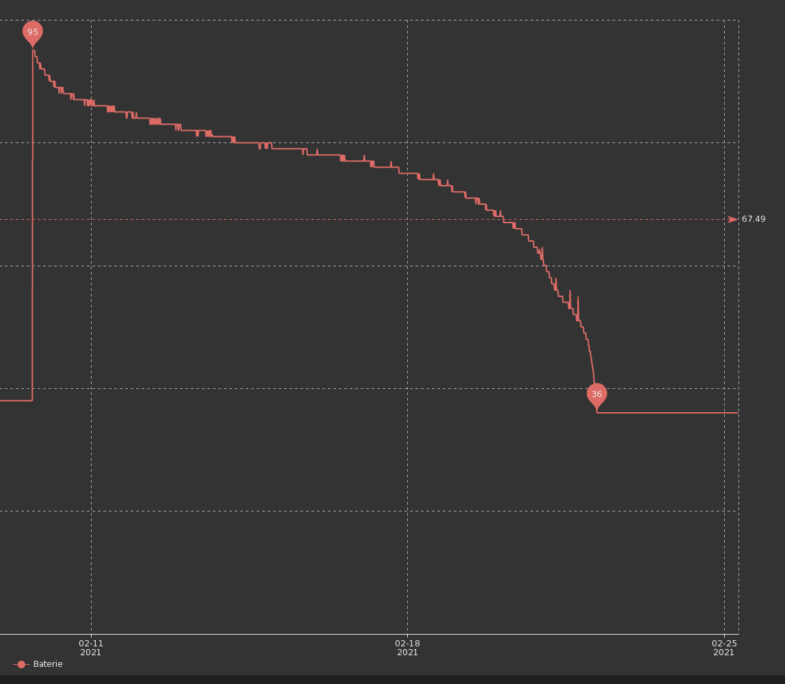
The node code is sleeping for 6 minutes between each sensing and sending data.
sleep(180000);14 days seems very short to me. Is that normal? Is there something I can to make it last longer?
Thanks
-
Hello
I would like to ask for help with passive battery powered node I created with following components:
- Arduino pro mini 8MHz - voltage regulator and power LED removed
- SX1276 based 868MHz LoRa radio
- BME680 sensor
- DC-DC 3.3V step-up booster
I created a battery measuring circuit according to scheme on this page ( https://www.mysensors.org/build/battery ).
The problem is the two fresh new AA batteries lasted less than 14 days and stopped when the circuit measured 36%.
2x1.5V AA Aerocell following start and end values:
09.02.2021 16:45 102% (start) : 1.610V and 1.610V
22.02.2021 04:15 36% (end) : 1.001V and -0.150VThe node code is sleeping for 6 minutes between each sensing and sending data.
sleep(180000);14 days seems very short to me. Is that normal? Is there something I can to make it last longer?
Thanks
@tssk could you post your sketch? Some things that could draw power:
- bme not turned off properly when sleeping the node
- lora transmits can take a long time, depending on which settings are used
Which booster are you using? A good booster will use almost no power when the node is sleeping. A bad booster will consume almost as much as if the node was not sleeping, so the performance of the booster will make a huge difference.
-
Hello
I would like to ask for help with passive battery powered node I created with following components:
- Arduino pro mini 8MHz - voltage regulator and power LED removed
- SX1276 based 868MHz LoRa radio
- BME680 sensor
- DC-DC 3.3V step-up booster
I created a battery measuring circuit according to scheme on this page ( https://www.mysensors.org/build/battery ).
The problem is the two fresh new AA batteries lasted less than 14 days and stopped when the circuit measured 36%.
2x1.5V AA Aerocell following start and end values:
09.02.2021 16:45 102% (start) : 1.610V and 1.610V
22.02.2021 04:15 36% (end) : 1.001V and -0.150VThe node code is sleeping for 6 minutes between each sensing and sending data.
sleep(180000);14 days seems very short to me. Is that normal? Is there something I can to make it last longer?
Thanks
@tssk Sending 240 messages a day is quite a lot for a battery node. I think you will need higher capacity batteries with that frequency of sending (is it really essential to send that often I wonder?).
Anyway, I am also testing battery nodes and as far as I can see the lora and bme are likely taking a lot of power. They must be 'put to sleep' as much as possible. AFAIK lora is an abbreviation of 'long range' and therefore means 'more power'. Can you test the current drawn by just the radio in sleep and transmitting?
Also, bootloader - I highly recommend using the minicore bootloader with internal 8MHz, bod as you wish (I ususally disable) and try again. My sleeping nodes use less than 5uA in sleep and I am trying to get that even lower this week.
Also check the value of pull-upresistors on the boards, they can be on the low side and perhaps better with higher value external ones (something I hope to test tomorrow as it happens).
Also temperature and humidity will have an effect. I put one test node on a colder NE facing window which has slept all the time except a twice daily battery check and send value only if changed. It is the only node to have changed from 100% to 99% in a week, so the colder window is clearly having an effect on the battery life in this situation.
As @mfalkvidd implied I would get rid of the stepup booster if at all possible, they are not so efficient and can produce a lot of noise on the power line. Can you go to 3xAA batteries? What about an 18650 li-on or two in parallel?
Finally check solder joints. A dry joint or cold joint may look OK but measure them with a meter just to make sure.
-
@tssk could you post your sketch? Some things that could draw power:
- bme not turned off properly when sleeping the node
- lora transmits can take a long time, depending on which settings are used
Which booster are you using? A good booster will use almost no power when the node is sleeping. A bad booster will consume almost as much as if the node was not sleeping, so the performance of the booster will make a huge difference.
-
I did not know that I need to turn BME off ů how to do that?
-
Only thing I found is that Arduino has deepSleep() - but I am not sure if I can use it.
-
I am using the default Bw125Cr45Sf128 but thinking about testing Bw125Cr48Sf4096 to achieve greater range.
-
Booster is the whining one - https://www.laskarduino.cz/step-up-boost-menic-s-me2108-33v-480ma/
-
Is there a way I can measure power draw with multimeter?
// Enable debug prints //#define MY_DEBUG // Enable passive mode #define MY_PASSIVE_NODE // Passive mode requires static node ID #define MY_NODE_ID 100 // Enable and select radio type attached //#define MY_RADIO_RF24 //#define MY_RADIO_NRF5_ESB //#define MY_RADIO_RFM69 #define MY_RADIO_RFM95 //#define MY_DEBUG_VERBOSE_RFM95 #define MY_RFM95_FREQUENCY (RFM95_868MHZ) //#define MY_RFM95_MODEM_CONFIGRUATION RFM95_BW31_25CR48SF512 #define MY_RFM95_CS_PIN 8 #define MY_RFM95_IRQ_PIN 2 #include <MySensors.h> #include <Wire.h> #include <SPI.h> #include <Adafruit_Sensor.h> #include "Adafruit_BME680.h" #define BME_SCK 13 #define BME_MISO 12 #define BME_MOSI 11 #define BME_CS 10 //#define SEALEVELPRESSURE_HPA (1013.25) // Initialize general message MyMessage msgTemp( 1, V_TEMP ); MyMessage msgHumi( 2, V_HUM ); MyMessage msgAirq( 3, V_LEVEL ); //Adafruit_BME680 bme; // I2C Adafruit_BME680 bme(BME_CS); // hardware SPI //Adafruit_BME680 bme(BME_CS, BME_MOSI, BME_MISO, BME_SCK); void setup() { analogReference(INTERNAL); if (!bme.begin()) { Serial.println( "ERR: BME680 not found" ); while (1); } // Set up oversampling and filter initialization bme.setTemperatureOversampling(BME680_OS_8X); //bme.setPressureOversampling(BME680_OS_4X); bme.setHumidityOversampling(BME680_OS_2X); bme.setIIRFilterSize(BME680_FILTER_SIZE_3); bme.setGasHeater(320, 150); // 320*C for 150 ms delay(2000); } void presentation() { // Send the sketch version information to the gateway and controller sendSketchInfo("Room sensor", "4.0"); // Register all sensors to gw (they will be created as child devices) wait(100); present( 1, S_TEMP ); wait(100); present( 2, S_HUM ); wait(100); present( 3, S_AIR_QUALITY ); } void loop() { int batt = analogRead( A3 ); // 1M, 470K divider across battery and using internal ADC ref of 1.1V // Sense point is bypassed with 0.1 uF cap to reduce noise at that point // ((1e6+470e3)/470e3)*1.1 = Vmax = 3.44 Volts // 3.44/1023 = Volts per bit = 0.003363075 int battP = batt / 10; #ifdef MY_DEBUG float battV = batt * 0.003363075; Serial.print( "Battery Voltage: " ); Serial.print( battV ); Serial.println(" V"); Serial.print( "Battery percent: " ); Serial.print( battP ); Serial.println(" %"); #endif wait(100); sendBatteryLevel( battP ); if (! bme.performReading()) { Serial.println( "ERR: BME680 reading failed" ); return; } float temp = bme.temperature; #ifdef MY_DEBUG Serial.print( "DBG: Temperature = " ); Serial.print( temp ); Serial.println( " C" ); #endif wait(100); send(msgTemp.set( temp, 2 )); /* float pres = bme.pressure/100.00; #ifdef MY_DEBUG Serial.print( "DBG: Pressure = " ); Serial.print( pres ); Serial.println( " hPa" ); #endif wait(100); send(msgPres.set(pres,2)); */ float humi = bme.humidity; #ifdef MY_DEBUG Serial.print( "DBG: Humidity = " ); Serial.print( humi ); Serial.println( " %" ); #endif wait(100); send(msgHumi.set( humi, 2 )); /* float alti = bme.readAltitude(SEALEVELPRESSURE_HPA); #ifdef MY_DEBUG Serial.print( "DBG: Approx. Altitude = " ); Serial.print( alti ); Serial.println( " m" ); #endif wait(100); send(msgPosi.set(alti,2)); */ float airq = bme.gas_resistance / 1000.0; #ifdef MY_DEBUG Serial.print("DBG: Gas Resistance = "); Serial.print( gas ); Serial.println(" KOhms"); #endif wait(100); send(msgAirq.set( airq, 2 )); sleep(10000); //sleep(180000); } -
@tssk Sending 240 messages a day is quite a lot for a battery node. I think you will need higher capacity batteries with that frequency of sending (is it really essential to send that often I wonder?).
Anyway, I am also testing battery nodes and as far as I can see the lora and bme are likely taking a lot of power. They must be 'put to sleep' as much as possible. AFAIK lora is an abbreviation of 'long range' and therefore means 'more power'. Can you test the current drawn by just the radio in sleep and transmitting?
Also, bootloader - I highly recommend using the minicore bootloader with internal 8MHz, bod as you wish (I ususally disable) and try again. My sleeping nodes use less than 5uA in sleep and I am trying to get that even lower this week.
Also check the value of pull-upresistors on the boards, they can be on the low side and perhaps better with higher value external ones (something I hope to test tomorrow as it happens).
Also temperature and humidity will have an effect. I put one test node on a colder NE facing window which has slept all the time except a twice daily battery check and send value only if changed. It is the only node to have changed from 100% to 99% in a week, so the colder window is clearly having an effect on the battery life in this situation.
As @mfalkvidd implied I would get rid of the stepup booster if at all possible, they are not so efficient and can produce a lot of noise on the power line. Can you go to 3xAA batteries? What about an 18650 li-on or two in parallel?
Finally check solder joints. A dry joint or cold joint may look OK but measure them with a meter just to make sure.
-
This is room sensor and I would like to react to changes in temperature and airquality - I was thinking that I could prolong the interval up to 12min. What do you think is optimal measurements rate for room thermostat?
-
Is it possible / necessary to put the radio module to sleep? How to do that?
-
So far I did not mess with the Arduino bootloader but I would like to :) Any link that I could read about it? And specifically about the minicore you mention?
-
I do not understand what you mean by the pull-up resistors?
-
I have my node in the middle of the room around 20-24C that sould not be the problem. Actually it is it main purpose to provide data for optimal room temperature.
-
I included step up boosted based on recommendation on the https://www.mysensors.org/build/battery page. I thought it should use the batteries most efficiently. I think I could go with 3 AA batteries. Will I need to regulate the voltage or can I power the radio and bme modules directly?
-
-
-
This is room sensor and I would like to react to changes in temperature and airquality - I was thinking that I could prolong the interval up to 12min. What do you think is optimal measurements rate for room thermostat?
-
Is it possible / necessary to put the radio module to sleep? How to do that?
-
So far I did not mess with the Arduino bootloader but I would like to :) Any link that I could read about it? And specifically about the minicore you mention?
-
I do not understand what you mean by the pull-up resistors?
-
I have my node in the middle of the room around 20-24C that sould not be the problem. Actually it is it main purpose to provide data for optimal room temperature.
-
I included step up boosted based on recommendation on the https://www.mysensors.org/build/battery page. I thought it should use the batteries most efficiently. I think I could go with 3 AA batteries. Will I need to regulate the voltage or can I power the radio and bme modules directly?
-
-
@tssk I use a threshold. I measure every 30 - 60 seconds. If a change goes pass the threshold I report immediately. Else I report periodically. I think I've created a small lib for that some years ago
-
You might need to turn off the BME, but that depends on how it works and what the Adafruit library handles for you.
My Sensors will turn off the radio when the Arduino goes to sleep so you don't need to sleep the radio manually.
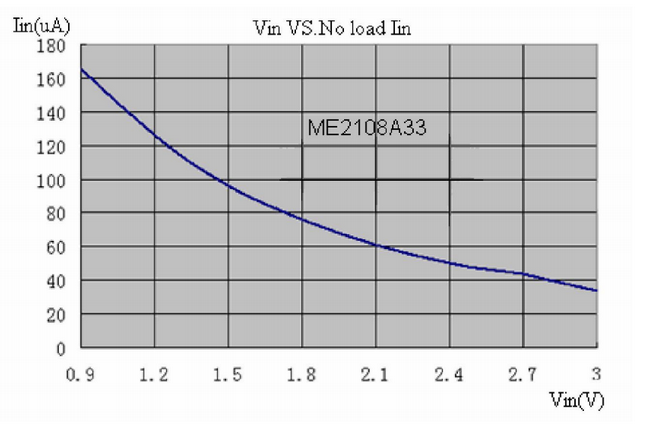
This diagram from the booster datasheet shows how much current it will consume with no load:
-
I hope I am measuring it correctly.
It shows 12.5 when in sleep and up to 90 when transmitting/measuring.
Any one can interpret that for me please? :)
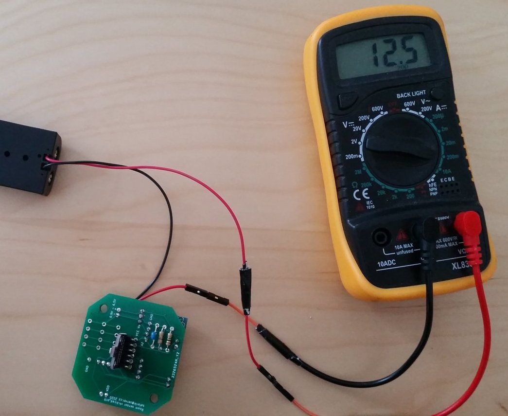
@tssk That is 12.5mA (12500uA) in sleep and up to 90mA (90000uA) in transmit mode. Compare that to my door/window sensor which is <5uA sleep and about 15uA transmit with nrf24l01+). Your current draw is too high for most 'normal' batteries to last very long as you have found out.
Minicore info and install instructions is here -- https://github.com/MCUdude/MiniCore.
Pull-up resistors are on the pcb and connect between data and Vcc as well as clock to Vcc. You won't gain a lot tampering with those with the figures you have posted so I would forget about those at the moment and concentrate on more productive things to get a lower current.
here is the bit of code to only send sensor variable when it has changed.....
if (int != oldint) {
    send(msgInt.set(int));
    oldint = int;
  }
This is used in my door sensor and can be used with any sensor variable name.
ALso of help would be to re-flash the node with MY_DEBUG to see how often your node is measuring and sending data. It shows if your prog is working as your expected it to (or not).
Anoother thought is that the sleep interval does not have to be fixed. You can vary it so that some times of day it is 20-30mins between read/send and at others you can reduce it if you think you need to.
-
@tssk That is 12.5mA (12500uA) in sleep and up to 90mA (90000uA) in transmit mode. Compare that to my door/window sensor which is <5uA sleep and about 15uA transmit with nrf24l01+). Your current draw is too high for most 'normal' batteries to last very long as you have found out.
Minicore info and install instructions is here -- https://github.com/MCUdude/MiniCore.
Pull-up resistors are on the pcb and connect between data and Vcc as well as clock to Vcc. You won't gain a lot tampering with those with the figures you have posted so I would forget about those at the moment and concentrate on more productive things to get a lower current.
here is the bit of code to only send sensor variable when it has changed.....
if (int != oldint) {
    send(msgInt.set(int));
    oldint = int;
  }
This is used in my door sensor and can be used with any sensor variable name.
ALso of help would be to re-flash the node with MY_DEBUG to see how often your node is measuring and sending data. It shows if your prog is working as your expected it to (or not).
Anoother thought is that the sleep interval does not have to be fixed. You can vary it so that some times of day it is 20-30mins between read/send and at others you can reduce it if you think you need to.
@skywatch said in 💬 Battery Powered Sensors:
@tssk That is 12.5mA (12500uA) in sleep and up to 90mA (90000uA) in transmit mode. Compare that to my door/window sensor which is <5uA sleep and about 15uA transmit with nrf24l01+
You mean 15mA transmit, right?
-
I removed the step up booster connected + directly to VCC but the node stopped working - only the arduino onboard led is constantly on.
I also tried to measure the step up booster alone and it is showing 0.05 at 20mA on multimeter settings.
I am now really confused and I am not sure what to conclude from that...
-
@skywatch said in 💬 Battery Powered Sensors:
@tssk That is 12.5mA (12500uA) in sleep and up to 90mA (90000uA) in transmit mode. Compare that to my door/window sensor which is <5uA sleep and about 15uA transmit with nrf24l01+
You mean 15mA transmit, right?
@mfalkvidd Yes - you got me ;)
I was confusing it with the battery pir which is 15-16uA in trigger mode. But yes, 15mA in Tx mode with a nrf24 module.
Maybe it is time for me to hibernate for a few months after all .....
-
I removed the step up booster connected + directly to VCC but the node stopped working - only the arduino onboard led is constantly on.
I also tried to measure the step up booster alone and it is showing 0.05 at 20mA on multimeter settings.
I am now really confused and I am not sure what to conclude from that...
@tssk said in 💬 Battery Powered Sensors:
I removed the step up booster connected + directly to VCC but the node stopped working - only the arduino onboard led is constantly on.
The problem was that the batteries I used were not completely fresh. I googled that Arduino pro mini need at least 2.7V to operate. Using fresh batteries the node is working. And it shows 6.0mA in sleep and 25.4mA when transmitting.
So using the stepup booster adds 6.5mA in sleep and 65mA when transmitting to consumption?
I also found LowPower library (https://github.com/rocketscream/Low-Power) but it seems to interfere with mysensors library (https://github.com/rocketscream/Low-Power/issues/80). Any experience?
-
@tssk said in 💬 Battery Powered Sensors:
I removed the step up booster connected + directly to VCC but the node stopped working - only the arduino onboard led is constantly on.
The problem was that the batteries I used were not completely fresh. I googled that Arduino pro mini need at least 2.7V to operate. Using fresh batteries the node is working. And it shows 6.0mA in sleep and 25.4mA when transmitting.
So using the stepup booster adds 6.5mA in sleep and 65mA when transmitting to consumption?
I also found LowPower library (https://github.com/rocketscream/Low-Power) but it seems to interfere with mysensors library (https://github.com/rocketscream/Low-Power/issues/80). Any experience?
The 2.7V is set in the fuses, you can go a lot lower if you disable Bod completely. I tested one with nrf24 and it worked down to 1.64V.
I think you will find that all the 'good stuff' from the low power library is included in mysensors sleep function anyway.
I suggest using minicore (it is easy to install and all works from within the arduino IDE you are used to) and set internal oscillator and disable BoD. You will need a programmer (a few dollars) or you can use another arduino as programmer. but that is more time consuming to set up and easier to mess up as well!
Good that you got rid of the booster!
-
The 2.7V is set in the fuses, you can go a lot lower if you disable Bod completely. I tested one with nrf24 and it worked down to 1.64V.
I think you will find that all the 'good stuff' from the low power library is included in mysensors sleep function anyway.
I suggest using minicore (it is easy to install and all works from within the arduino IDE you are used to) and set internal oscillator and disable BoD. You will need a programmer (a few dollars) or you can use another arduino as programmer. but that is more time consuming to set up and easier to mess up as well!
Good that you got rid of the booster!
@skywatch said in 💬 Battery Powered Sensors:
I think you will find that all the 'good stuff' from the low power library is included in mysensors sleep function anyway.
So when I use sleep() mysensors library overloads the generic arduino sleep?
I suggest using minicore (it is easy to install and all works from within the arduino IDE you are used to) and set internal oscillator and disable BoD. You will need a programmer (a few dollars) or you can use another arduino as programmer. but that is more time consuming to set up and easier to mess up as well!
I look at the git repo and I more confused now. I thought it is some kind of bootloader/firmware I flash. What is Arduino core? I never heard that term.
Good that you got rid of the booster!
I wonder why the booster is recommended here https://www.mysensors.org/build/battery ? Or did I misinterpreted?