💬 Battery Powered Sensors
-
@skywatch said in 💬 Battery Powered Sensors:
I suggest s simple node to test with, something like the door/window sensor with just one switch.
I'll do that, but for my thermal sensor the test cannot be more simple
......burn MiniCore bootloader with 9600 baud, 3.3V, 8MHz INTERNAL, BoD DISABLED.
I don't have the choice for the baud rate; Where is it located ?
Then add the radio module (you can try another if you have it
I swaped everything I could. (The radio modules that was connected to the single functionning sensor included)
what radio modules are you using? - A link or photo might help, there are bad ones and fakes that could be a problem for you).
Bought from Aliexpress;
Load your sketch and try again.
I have done the whole process hundreds and hundreds of time
You can measure the current to the whole set up and then just the radio to see if radio is not sleeping. ....
Yes I'll do that...
@Gilles-BILLARD It's in the sketch when you start serial interface. As an aside have you checked the baud rate the pro mini or uno you are using as a programmer - maybe it is 115200 and that is optimistic for a 3.3V board. Make sure the programmer is using 19200 just to be safe.
For inof I am using arduino ide 1.8.13 and musensors 2.3.2 with a £2 aliexpress serial prgrammer and have only encountered warnings about sck (which can safely be ignored)....
-
@skywatch said in 💬 Battery Powered Sensors:
I suggest s simple node to test with, something like the door/window sensor with just one switch.
I'll do that, but for my thermal sensor the test cannot be more simple
......burn MiniCore bootloader with 9600 baud, 3.3V, 8MHz INTERNAL, BoD DISABLED.
I don't have the choice for the baud rate; Where is it located ?
Then add the radio module (you can try another if you have it
I swaped everything I could. (The radio modules that was connected to the single functionning sensor included)
what radio modules are you using? - A link or photo might help, there are bad ones and fakes that could be a problem for you).
Bought from Aliexpress;
Load your sketch and try again.
I have done the whole process hundreds and hundreds of time
You can measure the current to the whole set up and then just the radio to see if radio is not sleeping. ....
Yes I'll do that...
-
@Gilles-BILLARD It's in the sketch when you start serial interface. As an aside have you checked the baud rate the pro mini or uno you are using as a programmer - maybe it is 115200 and that is optimistic for a 3.3V board. Make sure the programmer is using 19200 just to be safe.
For inof I am using arduino ide 1.8.13 and musensors 2.3.2 with a £2 aliexpress serial prgrammer and have only encountered warnings about sck (which can safely be ignored)....
@skywatch said in 💬 Battery Powered Sensors:
@Gilles-BILLARD It's in the sketch when you start serial interface. As an aside have you checked the baud rate the pro mini or uno you are using as a programmer - maybe it is 115200 and that is optimistic for a 3.3V board. Make sure the programmer is using 19200 just to be safe.
For inof I am using arduino ide 1.8.13 and musensors 2.3.2 with a £2 aliexpress serial prgrammer and have only encountered warnings about sck (which can safely be ignored)....
Ha, OKay; I've aslo supposed a pb from that, so I removed the sérial monitor and baud rate config.
And after the bootlaoder burning, the log is OKay.. the MEGA328P ID is also the good one and always the same for all 328 -
-
@Gilles-BILLARD It's in the sketch when you start serial interface. As an aside have you checked the baud rate the pro mini or uno you are using as a programmer - maybe it is 115200 and that is optimistic for a 3.3V board. Make sure the programmer is using 19200 just to be safe.
For inof I am using arduino ide 1.8.13 and musensors 2.3.2 with a £2 aliexpress serial prgrammer and have only encountered warnings about sck (which can safely be ignored)....
@skywatch said in 💬 Battery Powered Sensors:
...........have you checked the baud rate the pro mini or uno you are using as a programmer - maybe it is 115200 and that is optimistic for a 3.3V board.
The programmer is loaded with standard Arduino ISP sketch (19200 default baud rate)
-
@Gilles-BILLARD I understnad your frustration - I have been there myself.
I suggest s simple node to test with, something like the door/window sensor with just one switch.
Take your promini, remove leds and power regulator (or cut tracks) then burn MiniCore bootloader with 9600 baud, 3.3V, 8MHz INTERNAL, BoD DISABLED.
Then add the radio module (you can try another if you have it - what radio modules are you using? - A link or photo might help, there are bad ones and fakes that could be a problem for you). Load your sketch and try again.
You can measure the current to the whole set up and then just the radio to see if radio is not sleeping. ....
@skywatch said in 💬 Battery Powered Sensors:
@Gilles-BILLARD I understnad your frustration - I have been there myself.
I suggest s simple node to test with, something like the door/window sensor with just one switch.
I did that right away and the result is....
All's OKay without sleep(xxx):2021-04-10 17:38:22.898 Status: MySensors: Node: 52, Sketch Name: Temperature Sensor Sleep 2021-04-10 17:38:22.899 Status: MySensors: Node: 52, Sketch Version: GB.3.0 2021-04-10 17:40:25.515 (GiBi-Home) Light/Switch (Security Sensor) 2021-04-10 17:40:31.277 (GiBi-Home) Light/Switch (Security Sensor)Présentation then 2 minutes until I change the input twice
But with sleep() included...
2021-04-10 17:34:12.251 Status: MySensors: Node: 51, Sketch Name: Temperature Sensor Sleep
2021-04-10 17:34:12.251 Status: MySensors: Node: 51, Sketch Version: GB.3.0
2021-04-10 17:34:22.491 (GiBi-Home) Light/Switch (Security Sensor)
2021-04-10 17:34:22.486 Status: MySensors: Node: 51, Sketch Name: Temperature Sensor Sleep
2021-04-10 17:34:22.486 Status: MySensors: Node: 51, Sketch Version: GB.3.0
2021-04-10 17:34:32.561 (GiBi-Home) Light/Switch (Security Sensor)
2021-04-10 17:34:32.556 Status: MySensors: Node: 51, Sketch Name: Temperature Sensor Sleep
2021-04-10 17:34:32.556 Status: MySensors: Node: 51, Sketch Version: GB.3.0
2021-04-10 17:34:42.631 (GiBi-Home) Light/Switch (Security Sensor)
2021-04-10 17:34:42.626 Status: MySensors: Node: 51, Sketch Name: Temperature Sensor Sleep
2021-04-10 17:34:42.626 Status: MySensors: Node: 51, Sketch Version: GB.3.0
2021-04-10 17:34:52.701 (GiBi-Home) Light/Switch (Security Sensor)
2021-04-10 17:34:52.696 Status: MySensors: Node: 51, Sketch Name: Temperature Sensor Sleep
2021-04-10 17:34:52.696 Status: MySensors: Node: 51, Sketch Version: GB.3.0
2021-04-10 17:35:02.772 (GiBi-Home) Light/Switch (Security Sensor)
2021-04-10 17:35:02.767 Status: MySensors: Node: 51, Sketch Name: Temperature Sensor Sleep
2021-04-10 17:35:02.767 Status: MySensors: Node: 51, Sketch Version: GB.3.0
2021-04-10 17:35:12.842 (GiBi-Home) Light/Switch (Security Sensor)
2021-04-10 17:35:12.837 Status: MySensors: Node: 51, Sketch Name: Temperature Sensor Sleep
2021-04-10 17:35:12.837 Status: MySensors: Node: 51, Sketch Version: GB.3.0
2021-04-10 17:35:22.913 (GiBi-Home) Light/Switch (Security Sensor)
2021-04-10 17:35:22.908 Status: MySensors: Node: 51, Sketch Name: Temperature Sensor Sleep
2021-04-10 17:35:22.908 Status: MySensors: Node: 51, Sketch Version: GB.3.0
2021-04-10 17:35:32.984 (GiBi-Home) Light/Switch (Security Sensor)
2021-04-10 17:35:32.979 Status: MySensors: Node: 51, Sketch Name: Temperature Sensor Sleep
2021-04-10 17:35:32.980 Status: MySensors: Node: 51, Sketch Version: GB.3.0
2021-04-10 17:35:43.055 (GiBi-Home) Light/Switch (Security Sensor)
The same kind of reboot up to présentation()
So sad !
NOTA: The sketch is the one provided as an example in BinarySwitchSensor.ino sketch
I've just added sleep( 10000) a the very end. -
@skywatch said in 💬 Battery Powered Sensors:
@Gilles-BILLARD I understnad your frustration - I have been there myself.
I suggest s simple node to test with, something like the door/window sensor with just one switch.
I did that right away and the result is....
All's OKay without sleep(xxx):2021-04-10 17:38:22.898 Status: MySensors: Node: 52, Sketch Name: Temperature Sensor Sleep 2021-04-10 17:38:22.899 Status: MySensors: Node: 52, Sketch Version: GB.3.0 2021-04-10 17:40:25.515 (GiBi-Home) Light/Switch (Security Sensor) 2021-04-10 17:40:31.277 (GiBi-Home) Light/Switch (Security Sensor)Présentation then 2 minutes until I change the input twice
But with sleep() included...
2021-04-10 17:34:12.251 Status: MySensors: Node: 51, Sketch Name: Temperature Sensor Sleep
2021-04-10 17:34:12.251 Status: MySensors: Node: 51, Sketch Version: GB.3.0
2021-04-10 17:34:22.491 (GiBi-Home) Light/Switch (Security Sensor)
2021-04-10 17:34:22.486 Status: MySensors: Node: 51, Sketch Name: Temperature Sensor Sleep
2021-04-10 17:34:22.486 Status: MySensors: Node: 51, Sketch Version: GB.3.0
2021-04-10 17:34:32.561 (GiBi-Home) Light/Switch (Security Sensor)
2021-04-10 17:34:32.556 Status: MySensors: Node: 51, Sketch Name: Temperature Sensor Sleep
2021-04-10 17:34:32.556 Status: MySensors: Node: 51, Sketch Version: GB.3.0
2021-04-10 17:34:42.631 (GiBi-Home) Light/Switch (Security Sensor)
2021-04-10 17:34:42.626 Status: MySensors: Node: 51, Sketch Name: Temperature Sensor Sleep
2021-04-10 17:34:42.626 Status: MySensors: Node: 51, Sketch Version: GB.3.0
2021-04-10 17:34:52.701 (GiBi-Home) Light/Switch (Security Sensor)
2021-04-10 17:34:52.696 Status: MySensors: Node: 51, Sketch Name: Temperature Sensor Sleep
2021-04-10 17:34:52.696 Status: MySensors: Node: 51, Sketch Version: GB.3.0
2021-04-10 17:35:02.772 (GiBi-Home) Light/Switch (Security Sensor)
2021-04-10 17:35:02.767 Status: MySensors: Node: 51, Sketch Name: Temperature Sensor Sleep
2021-04-10 17:35:02.767 Status: MySensors: Node: 51, Sketch Version: GB.3.0
2021-04-10 17:35:12.842 (GiBi-Home) Light/Switch (Security Sensor)
2021-04-10 17:35:12.837 Status: MySensors: Node: 51, Sketch Name: Temperature Sensor Sleep
2021-04-10 17:35:12.837 Status: MySensors: Node: 51, Sketch Version: GB.3.0
2021-04-10 17:35:22.913 (GiBi-Home) Light/Switch (Security Sensor)
2021-04-10 17:35:22.908 Status: MySensors: Node: 51, Sketch Name: Temperature Sensor Sleep
2021-04-10 17:35:22.908 Status: MySensors: Node: 51, Sketch Version: GB.3.0
2021-04-10 17:35:32.984 (GiBi-Home) Light/Switch (Security Sensor)
2021-04-10 17:35:32.979 Status: MySensors: Node: 51, Sketch Name: Temperature Sensor Sleep
2021-04-10 17:35:32.980 Status: MySensors: Node: 51, Sketch Version: GB.3.0
2021-04-10 17:35:43.055 (GiBi-Home) Light/Switch (Security Sensor)
The same kind of reboot up to présentation()
So sad !
NOTA: The sketch is the one provided as an example in BinarySwitchSensor.ino sketch
I've just added sleep( 10000) a the very end.@Gilles-BILLARD Inoticed the following in the sketch you posted above...
  // ************Sleeping test ***************
    #ifdef MY_DEBUG
        delay(10000); // 10 secondes
    #else
        sleep(10000);
    #endif
}
Delay should be replaced by Wait in mysensors code to avoid blocking.
I always went by the old saying that when you are in a hole, stop digging. I have not seen the behaviour you show before. I can only suggest that you run the EEPROMclear sketch (file>examples>mysensors>cleareepromconfig) and try again. Check the voltage to the promini is stable and the radio has the recommended capacitor. You might be surprised at the difference a good clean power supply can make.
#is the gateway running on the same power supply? IS GW receiving messages? Please provide the FULL debug output on the serial monitor. That snippet doesn't help much.
-
Please, have a look at the time stamps:
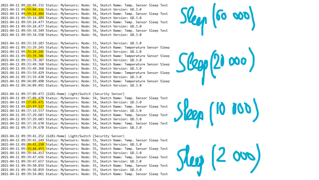
More or less 10 seconds if sleep time >= 10 000 ms
Only a little more than 3 sec if sleep time = 2 000 ms
Could it help ?@Gilles-BILLARD I would like to think along to help, but lost you many posts back...
All was ok, so what did you change (and why) and what is the real issue right now?
And as @skywatch indicates, post the full log, sketch and everything. Don't try to filter information yourself, you might miss something. -
Finally, I found it….
A big thank you to all those who helped;
Here's my report in case it could be usefull to others (so, they will not waste as much time as I did)
All began with my FTDI refusing to work with the MiniCore library, returning this classic error code: "avrdude: error: could not find USB device with vid-0x16c0 pid-0x5dc vendor'www.fischl.de' product'USBasp' when I wanted to reprogram a ProMini.
So I opted for programming via another ProMini (Arduino as ISP)
The first ProMini was able to receive the MiniCore bootloader and then my sketch without any problem, but the followings did’nt....No error message was reported; I spent 9 days trying hundreds of times changing only one thing at a time... unsuccessfully.
But this morning I tried again using version 2.0.0 of Arduino’s IDE, and here I received an error message; "Impossible to recognize the Arduino as ISP" !!!!
Eureka.... I had the idea to inject the MiniCore BootLoader + the “Arduino ISP” sketch in the 2nd via the IDE Arduino 1.8.13 and then use this very 2nd one to program others; At that moment, everything became normal; The tests were ok and went to "sleep" so I loaded my sketch and everything is good now.
So: If you try to use Arduino as ISP with MiniCore Both Arduinos sould have been burnt with MiniCore BootLoader
Thank you again.PS: Could the admin delete all my useless posts ?
-
@Gilles-BILLARD I would like to think along to help, but lost you many posts back...
All was ok, so what did you change (and why) and what is the real issue right now?
And as @skywatch indicates, post the full log, sketch and everything. Don't try to filter information yourself, you might miss something.@Yveaux said in 💬 Battery Powered Sensors:
.... All was ok, so what did you change (and why)
A the very beginning, hesitating with the procedure, I've probably burnt the Minicore bootloader in the programming ProMini without noticing it... That's the only explanation I see.
-
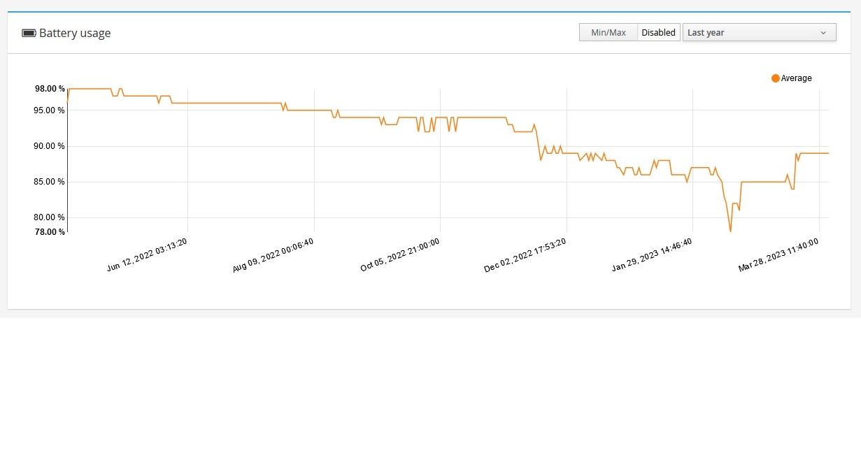
Just completed 1 year of operation of a PIR sensor in the house that trigger 100-200 times a day. It is powered by 2xAA batteries and here is a graph of battery level over the year.
-
@skywatch If your project is free and open, where i can look at it? At the moment i need to solve same problem. On your graph what will be 0% ? For mine devices it is minimum 1.9v, for few it is 2.2v
@nekitoss
I used 3.3V pro mini with regulator removed and powered by Vin pin. Also removed leds from the pro mini.I used minicore bootloader.
I used the small pir sensors and again removed the regulator to power directly from the pro mini outputs.
After that sleep the node and trigger on interrupt.
Send battery level once a day.
Use inbuilt battery level monitor and not external components that constantly drain power to get battery level.
1.8V is 0% on the graph (not visible yet!) but I have had nodes working below 1.7V It's a matter of luck with that it seems.
Hope this helps you on the right track. I'll try and help if you want.
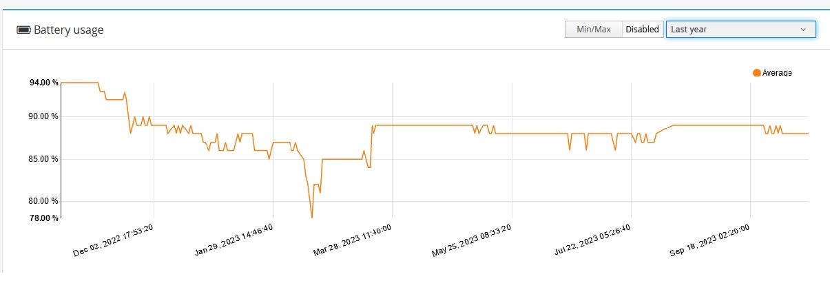
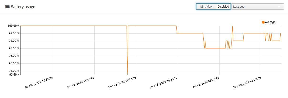
This is the latest image and still going strong after 18 months. Voltage is at 2.903V
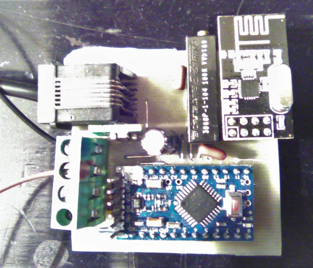
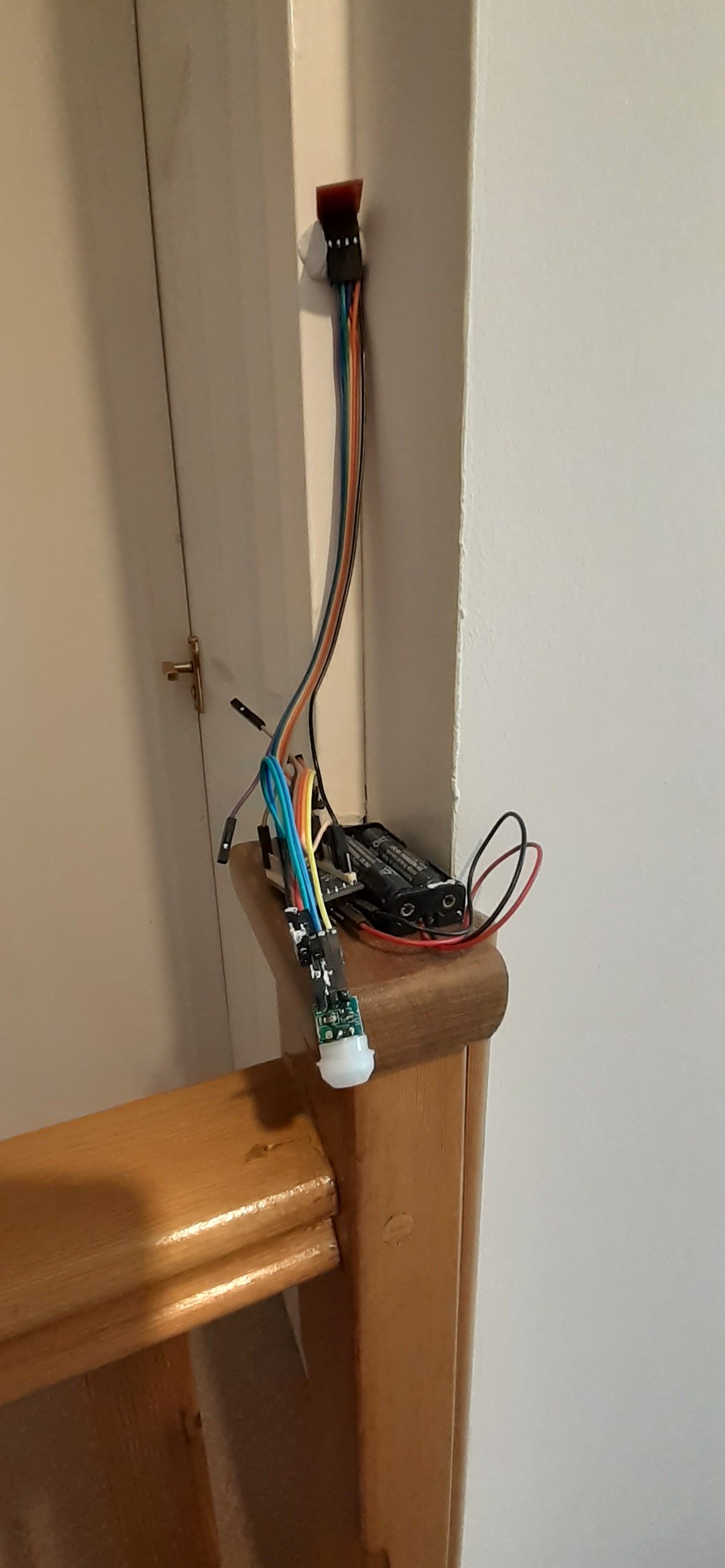
Here is photo of the test example - I need to make a case and produce more of them over winter.....
Here is the same build/code of a window sensor. Similar time frame but hardly triggered.....