Minimal design thoughts


  • Admin

    I'm thinking about spinning up the good old eagle cad program again, and start creating sensor boards (Like so many others here :))

    Only thing is, that unlike (almost) everyone else, that are using normal arduino micro boards, I'm thinking about skipping that part, and create my "own" arduino board, thinking about the following:

    1. use atmega 328 tqfp (That's doable for home soldering :))
    2. pads for a 32Khz crystal, for timing purposes
    3. Standard atmel programming header.
    4. ftdi header like on arduino mini, so could use arduino bootloader (could be some details about the baudrate though, as it's running off internal RC oscillator)
    5. Using Si7021 integrated humidity / temperature sensor, footprint for bmp180 barometric sensor
    6. skip power converters, run everything off a battery directly (disable brownout detection in atmel)
    7. SPI flash / e2prom onboard. Using same connections as moteino from lowpowerlabs, so should be able to use same bootloader for updates to firmware
    8. pinheader for connecting radio module
    9. Pinheader for D3-D7 on one side, and SDA/SCL + A0/A1 and power on the other side
    10. Formfactor is 30x17.5mm (almost same size as the NRF24 module).
    11. ATSHA204A sot23 footprint on board (Connected to A3). Can be used for SHA256 key exchange and verification
    12. status LED (on A2)

    Any thoughts about this? Or should I wait for the all in one mysensors battery sensor board? (When will that be available?)

    / Thomas

    (Spec updated January 28th, 2015)


  • Hero Member

    @Thomas-Bowman-Mørch Please open source the design if you do! Would be interesting to see how small you can make it.

    I'd still like to see space for a 3.3V regulator of some sort though. Even if it means a few more components, at the very least 2x capacitors and 1x inductor. And the nrf24 probably shouldn't hang right over the inductor, even if it is shielded, seeing as there have been so many iffy issue with that chip. Even if the atmel can run at really low voltages, many sensors, like the DS18B20 don't seem to be able to. With a regulator, we'd have much more freedom to choose from 1xAA/AAA or 2xAA/AAA etc.


  • Hero Member

    With a regulator you have indeed more freedom but it is less minimal and .. there are already other boards doing it that way.

    My question would be how exactly you like to power the board.

    I see the nRF24L01 can run from 1.9 Volts and the ATmega328 is said to work down to 1.8V but what about the sensors you are planning to use?


  • Admin

    I haven't been looking too deeply into the different sensor datasheets yet. But yes, it seems like the Dallas chip doesn't like voltages below 3V. What a bummer..

    Main purpose was actually to make things as small as possible, but still be able to hand solder things.

    / Thomas


  • Hero Member

    Have been thinking about this in the past and what could be done is (apart from searching another sensor) to only generate the 3V when the sensor is about to be read and switch it off afterward.

    Not really making things "as small as possible" but as making things as less power hungry as possible.


  • Mod

    @Thomas-Bowman-Mørch I am thinking about the same thing but with power converter.

    I have a board with a Mini Pro and flash memory chip right now but want to get rid of the Arduino (not the chrystal though based on input from several sources).

    I would even want to make the NRF24 on board instead of using a module.
    The same for the converter.

    Getting rid of the Arduino is a no-brainer imho but the on-board NRF24 and converter are less easy to do...


  • Hero Member

    I would even want to make the NRF24 on board instead of using a module.
    The same for the converter.

    That sounds good and will likely come with better reliability.

    The board layout for the NRF24 should not be too hard, I think you can get the design for the Nordim Semicondutor site. More problematic can be the soldering and tuning the RF, although I am not convinced the standard boards has good tuning done.

    What makes the convertor less easy you think?


  • Admin

    @marceltrapman Originally I was thinking about making everything on a single board (also with the nrf24 on board). But the modules are dirt cheap, and I don't like to hand solder the NRF chip (too small footprint).

    So that's the reason to just plug it in as a module.

    @daulagari Had been thinking about the exact same thing, after discovering the problem with DS18x20 and supply voltage. I stumbled uppon MCP1640 from microchip, which can go into pass-through when disabled. And then probably a TPS27081A from TI to disable power to the sensors, when in sleepmode.

    The thought was that when it powers up sensors for measuring, it also ramps up the supply voltage to the atmel. (Actually there is a application note describing this somewhere on microchips site)

    But then we are back to putting on inductors etc (and finding reliable sources for them). Damn, I sometimes miss my old job at a hardware design house, where we had a fairly large stock of 'generic' components in the house for experiments.

    / Thomas


  • Mod

    @daulagari said:

    What makes the convertor less easy you think?

    Thinking out loud (and for myself) I lack the skills to decide what components to use.

    @Thomas-Bowman-Mørch

    But the modules are dirt cheap

    I agree but there are pro's as well and if price is the only con I would go for it 🙂

    and I don't like to hand solder the NRF chip

    Use a rework blower. Works well...


  • Admin

    @marceltrapman

    I see "multiple" cons with embedding the nrf chip:

    1. Components too small to handsolder (yes you could use rework blower, but then you must buy one in order to populate the boards yourself).
    2. RF design is not for kids 🙂 antenna design, impedance matching etc. (There must be a reason to why we considered the RF guys as gurus, when I worked at the design house)
    3. They are still cheap 🙂

    the only pro to embedding it, is actually to make things relatively smaller, than with two modules packed together.

    And taking RF design into consideration, then I don't think it is possible to make things that much smaller, because the RF is as it should be, can't be smaller.. (other than maybe go with 4 layer boards, in order to get solid gnd plane) Placing components on both sides of the PCB. And then the price for the PCB goes up, comparing it to 2 layer pcb's

    / Thomas


  • Hero Member

    @Thomas-Bowman-Mørch

    it seems like the Dallas chip doesn't like voltages below 3V. What a bummer..

    Are you married with the Dallas chip? 😉

    Had a look at the Internet and there are at least low-voltage temperature sensors, see for example the DS75LV.

    The thought was that when it powers up sensors for measuring, it also ramps up the supply voltage to the atmel. (Actually there is a application note describing this somewhere on microchips site)

    Why also "power up" the Atmel?


  • Admin

    @daulagari said:

    Are you married with the Dallas chip? 😉

    Had a look at the Internet and there are at least low-voltage temperature sensors, see for example the DS75LV.

    DS75LV has an accuracy of +/- 2 degrees celcius, while DS18s20 have +/- 0.5 degrees. Also, I really like the ability to have as many sensors hanging on the same single wire, as you desire.

    I also had a look at the DHT22 (I know, there probably are other chips out there for doing combined humidity and temperature measurements) but that is also spec'ed to minimum 3.3V operating voltage.

    Why also "power up" the Atmel?

    To keep the logic levels the same for sensors and the atmel, And for switching to a higher working frequency when it wakes up for doing measurements (if necessary).


  • Hero Member

    DS75LV has an accuracy of +/- 2 degrees celcius, while DS18s20 have +/- 0.5 degrees.

    Yes also saw that and meant another IC, the DS620.

    Also, I really like the ability to have as many sensors hanging on the same single wire, as you desire.

    "For distributed-sensing applications, it is multidroppable with three address pins that allow up to eight DS620s to operate on a single bus."

    Why also "power up" the Atmel?

    To keep the logic levels the same for sensors and the atmel, And for switching to a higher working frequency when it wakes up for doing measurements (if necessary).

    That does not sound like a "minimal design" 😉


  • Admin

    @daulagari said:

    DS75LV has an accuracy of +/- 2 degrees celcius, while DS18s20 have +/- 0.5 degrees.

    Yes also saw that and meant another IC, the DS620.

    Also, I really like the ability to have as many sensors hanging on the same single wire, as you desire.

    "For distributed-sensing applications, it is multidroppable with three address pins that allow up to eight DS620s to operate on a single bus."

    Still it's i2c bus, which means 4 wires (GND, VCC, SDA, SCL), while DS18x20 is 2 wires (GND and Data/VCC)

    Why also "power up" the Atmel?

    To keep the logic levels the same for sensors and the atmel, And for switching to a higher working frequency when it wakes up for doing measurements (if necessary).

    That does not sound like a "minimal design" 😉

    I know, that kinda blew the 'minimal design' away (a little), because I discovered that the sensors that I had in mind need at least 3V (some even 3.3V). If the sensors need 3.3V, and I need a powerconverter onboard, then I might as well make it possible to ramp up the voltage to the atmel.

    Anyways, main design details is still in my head. Need to get it on paper soon..

    / Thomas


  • Mod

    This NRF24 module and even cheaper ones (also mini 10 pcs 6 USD) could be an addition/alternative for minimal radio design.


  • Admin

    @daulagari

    Why also "power up" the Atmel?

    To keep the logic levels the same for sensors and the atmel, And for switching to a higher working frequency when it wakes up for doing measurements (if necessary).

    That does not sound like a "minimal design" 😉

    I have studied the datasheets for a couple of sensors, and the atmega now, and come to the conclusion that if one needs to use 3.3V sensors, one need to boost the supply voltage to the atmega as well.

    Absolute maximum ratings on any input pin for the atmega is VCC + 0.5V. This means, that if bat voltage is 1.8V, maximum high voltage is 2.3V on the input pin of the atmega.

    Also, the minimum high voltage of ds18b20 (I know, I keep comming back to this one :)) is 3V (or 2.2V if running with local power). Which means that you need to have the atmel chip running on the same voltage as the sensors.

    So it won't work if the atmel is powered directly from batt, and sensors are running of a converter.

    Of course I could find alternative sensors, but I really like the ds18x20 as you only need 2 wires to the chip, if you need "remote" sensing (I have one place where I want to measure 5-6 temperatures on the central heating distribution that eases up things, that I only need 2 wires to each temperature sensor)

    But let's see, I'm still searching for different sensors.

    / Thomas


  • Admin

    Think that I have prety much settled for a Si7021 as temperature / humidity sensor, instead of DS18b20

    Ok, it's a tiny chip (3x3mm DFN6 package) so it might be a beast to solder. But it goes down to 1.8V on VCC, so well suited for battery operation, together with the atmel and radio.

    I have been arround a couple of iterations with DS18b20 and step-up, because I need one node to be able to measure multiple temperatures. But this is 1 node, whereas the rest only needs temperature / humidity, which can be covered with Si7021. I have also thought about throwing in the opportunity to use a PIR sensor on the nodes as well, just for the fun of it. But then I need the step-up, as the PIR sensor needs 3V minimum.

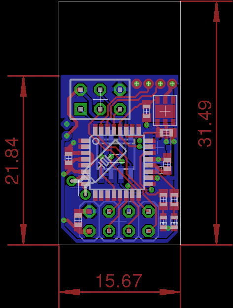
    Right now, board dimensions with Si7021, 328p, spi flash, no stepup, is down to 15x21mm (smaller than the radio module). Might throw in a footprint for bmp180 as well, so I could equip one of the sensors with barometric sensor.. The complete sensor could fit on the end of a 2xAA battery holder (they are roughly 15x32x60mm).


  • Hero Member

    Right now, board dimensions with Si7021, 328p, spi flash, no stepup, is down to 15x21mm (smaller than the radio module).

    Nice, that sounds really like a minimal module!


  • i'm also making my own sensor right now and the si7021 is very interesting for removing my BIG dht11. But for home made soldering, the center ground pad should be soldered or it's not necessary?


  • Hero Member

    Sounds very interesting! Though personally I'd rather have a good regulator / boost (even if it is in a separate module) than having to source particular components that will run at 1.8V.

    How do you plan to integrate the nrf24? The "standard" or the "mini" version?

    I would love it if the MySensors web site could have a department of open source pcb schematics just like it has models for 3D printing.

    Soldering sounds tricky, you'd either have to reflow or heat the underside of the DFN6 on the pcb. With extra flux and paste.


  • Admin

    @Tibus said:

    But for home made soldering, the center ground pad should be soldered or it's not necessary?

    To my best knowledge, there is no "center ground pin" on the Si7021? Or I have missed something. A friend of mine got a couple of them for another project, so I'll check up with him on the physical appearance, next time we get together.

    @bjornhallberg said:

    Sounds very interesting! Though personally I'd rather have a good regulator / boost (even if it is in a separate module) than having to source particular components that will run at 1.8V.

    Btw. pricewise, comparing DHT22 and Si7021 they are about the same price (ebay price on DHT22, and mouser price for Si7021). So for sourcing DS18b20/DHT22, or sourcing the Si7021, is not that big a difference. I also can skip the stepup converter, and save a couple of $ there..

    How do you plan to integrate the nrf24? The "standard" or the "mini" version?

    It's the standard version, piggybacking on the minisensor. Actually (on the nrf24 modules that I have), the component area is 15x20mm (excluding the antenna part) So my arduino-clone could fit without "covering" the antenna..

    I would love it if the MySensors web site could have a department of open source pcb schematics just like it has models for 3D printing.

    That would be great.. 🙂

    Anyway, I'll take a few more stabs at the schematic / layout before I publish it here..


  • @tbowmo

    Yes there is a TGnd Pad in the middle :

    http://www.silabs.com/Support Documents/TechnicalDocs/Si7021.pdf
    page 26... But I'll buy a Hot Air soldering station, i'll be easier to solder no?


  • Admin

    @bjornhallberg said:

    I would love it if the MySensors web site could have a department of open source pcb schematics just like it has models for 3D printing.

    Yes, I would gladly create a section for this on the main site. But maybe we could start a pinned thread linking the once available?


  • Hero Member

    @Tibus Or perhaps you have a hot air gun in the toolbox. Not as elegant but it might do.

    I'd much rather not try hot air (only have this at my disposal) and instead try to get at the pad from the backside of the pcb:
    http://www.eevblog.com/forum/projects/soldering-dfn-and-qfn-devices/
    With flux and paste possibly it should be quite easy. And besides, you'd need flux and/or paste for hot air reflow as well.


  • Admin

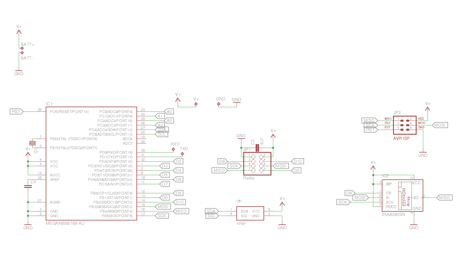
    Schematic as it is at the moment:
    sensor-alpha1.png

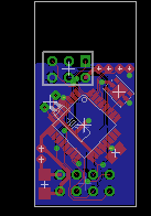
    And the board as it is right now
    sensor-alpha1-brd.png

    I know it says eeprom for IC2, but the footprint is the same for SPI flashes.

    the eeprom is placed on the bottom layer. Also, the nrf24 is placed on the bottom (so the eeprom is "in the middle of the sandwich". The dimensions of the total board will be about 15x30mm. This is the same size as the radio module. The empty area on the top is the area below the antenna.

    Still need to make changes to the DFN package (upper right). and make a footprint for a bmp180 barometric sensor (and find a good home for it on the board).

    Also, need to tidy up the routing, I used the autorouter which is very bad at placing the traces (haven't got any better since I used eagle the last time 11 years ago..) So maybe I just end rip everything up and hand route it by hand (this is the fun part of pcb designs, trying to mingle everything in to place 🙂 thinking about the things my teacers told me 20 years ago about PCB design (oh f*ck I feel like an old geezer now! :))

    Oh yeah, btw. there is also made room for a crystal (32Khz) on there.


  • Admin

    And yes, I know i'm missing pull ups on i2c bus, and decoupling capacitors on the 328


  • Admin

    This will be a very small board indeed! Not an expert but couldn't the radio interfere with MCU at these short distances?


  • Admin

    @hek

    This will be a very small board indeed! Not an expert but couldn't the radio interfere with MCU at these short distances?

    It would be more the other way arround. The MCU is making trouble for the receive path of the radio module. But the radio module has a large gnd plane on the bottom towards the mcu board, so it should be shielded.


  • Admin

    A new schematic / layout

    I'm almost ready for sending it off to China, and get some boards back 🙂

    Changes since last:
    2 LED's added (figured debug output could be nice)
    pullups added on i2c bus
    caps changed to 0603 footprint
    added a couple of extra caps for decoupling (MCU)
    Added BMP180 barometric sensor (only need 1 node with this one though)
    Moved components arround, squeezing things a little bit more together.
    Routed manually this time, not that big a board, so no need to use the autorute function

    Testpads on upper right corner of the pcba is GND, RXD/TXD and VCC, again nice to have serial available for debugging the first couple of boards.

    Board is designed with dirtypcbs.com in mind for production (Used their DRU file in eagle to check things).

    Schematic:
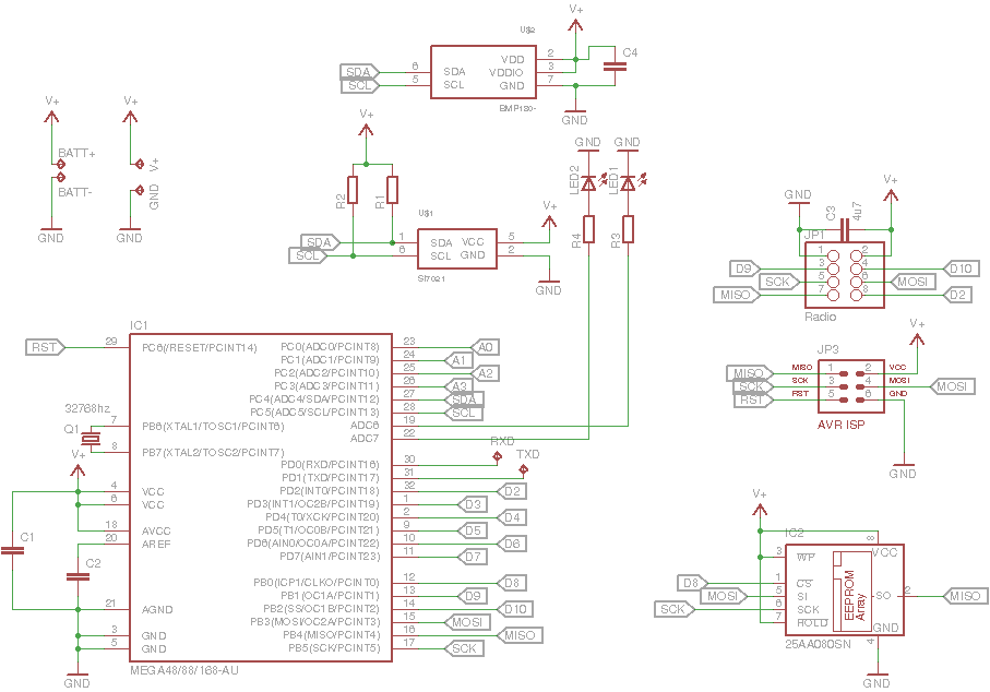
    sensor-alpha2.png

    and pcb layout:
    sensor-alpha2-brd.png


  • Hero Member

    Fantastic! But I agree that is is perhaps a bit odd to have a footprint for a BMP180 on every board. You'll get a lot of boards when ordering 10x 5x5cm PCBs.

    0603 ... time to get soldering. Haha. But those solder pads look pretty big actually. Is this the issue where Eagle actually makes 0603 caps more solderable than 0805 by making the pads longer?


  • Admin

    @bjornhallberg said:

    Fantastic! But I agree that is is perhaps a bit odd to have a footprint for a BMP180 on every board. You'll get a lot of boards when ordering 10x 5x5cm PCBs.

    I know, but I thought that I just as well could put one in there when I was designing the pcb. Otherwise I would have to get it on an external pcb (sparkfun sells bmp180 breakut boards). And there was room for it 🙂

    0603 ... time to get soldering. Haha. But those solder pads look pretty big actually. Is this the issue where Eagle actually makes 0603 caps more solderable than 0805 by making the pads longer?

    Don't know, last time I used eagle (about 10 years ago) I made layouts with 0805 components, (and an atmega8). Actually I think that the board I made back then is still being used in production.

    /Thomas


  • Hero Member

    Any thoughts on how to panelize it? You'd get like six boards on a 5x5 if those dimensions hold? Perhaps you could do some alternative layouts for different sensors? I understand dirtypcbs no longer do grooving (if they ever did) ... how much pcb space is lost to routing typically?

    In case anyone else is wondering about dirtypcbs, they seem to do an ok job typically:
    http://lab.kjlr.dk/p/handystick
    http://hackers.gallery/236/electronics/pcb-itead-studio-vs-dirtypcbs


  • Admin

    The full size is 16x31 mm at the moment. So it's almost the same size as the normal nrf24 modules on ebay. So if I panelize them i can get 4 modules in total on a single 5x5 area.

    Let's see when i come around to order them. I just like the dirty pcb as it reminds me of a song from my favorite rockband (ac/dc) 🙂


  • Admin

    Arh.. just found out that the pinheader for the radio was turned 180 degrees, so instead of the 2 boards being on top of eatch other, they would "go in two different directions". Had to rip up most of the board, and re-arrange things again.
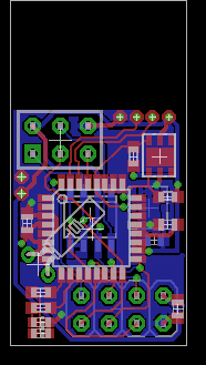
    sensor-alpha3-brd.png

    only changes on the schematic, is that the LED's are moved to a couple of other pins.

    / Thomas


  • Very interesting, this one board would cover all that I need for the majority of my sensors. Would need a couple of sensors with IR, and a couple of others. Is the reason for this the reduced foot print, a reduced cost over arduino pro's, or something else?


  • Admin

    @NotYetRated

    One of the reasons is that I wanted to go with battery, without all the extra "cruft" that is on standard arduino boards (like regulators etc.),

    Also I want to make it as clean as possible, as I'm planning on creating 10-20 nodes in total I don't like to make them as "birdsnests" with multiple boards stiched together with wires.

    It also almost became an obsesson to see how small I could get it :).

    Maybe I can save a little $ by roling my own layout, but not the main driving force.


  • @tbowmo Ahh, understood! I too plan for, somewhere around 20 nodes. However I plan to wall wort power most of mine. The only real exception will be a few outside, and inconvenient to reach places.

    I do like the idea of eliminating as much of the "birds nest" as possible... My first couple of, what I am currently calling prototype sensors, are, well inside their boxes, very ugly. haha.


  • Hero Member

    @tbowmo Very nice design!

    Personally I would make something similar but with the option to charge things using an external solar cell or just a charger. With the new generation of low-leakage NiMH rechargeable batteries I am very tempted using these to power the sensor.


  • Admin

    @daulagari

    Is it necessary to use solar power? A couple of standard AA batteries, is probably good for 2000mAh, and with a consumption of below 50uA, you got battery power for 4-5 years..

    Also the sun doesn't shine inside my house 😉

    / Thomas


  • Hero Member

    Is it necessary to use solar power? A couple of standard AA batteries, is probably good for 2000mAh, and with a consumption of below 50uA, you got battery power for 4-5 years..

    Sounds great, 4-5 years without changing batteries but will that be real? The bad thing is that if true it take 4-5 years to prove it.

    Also the sun doesn't shine inside my house

    But a solar cell does not need solar to generate (some) current unless your house is completely dark 😉

    But yes, if it is only 2-3 year going with rechargeable batteries is overkill.


  • Admin

    @daulagari said:

    Is it necessary to use solar power? A couple of standard AA batteries, is probably good for 2000mAh, and with a consumption of below 50uA, you got battery power for 4-5 years..

    Sounds great, 4-5 years without changing batteries but will that be real? The bad thing is that if true it take 4-5 years to prove it.

    Probably not 4-5 years (it was just quick, off the head, calculations), but I would think that at least 2 years of service time should be obtainable.. But yes, we will first see it in a couple of years 😄

    Also the sun doesn't shine inside my house

    But a solar cell does not need solar to generate (some) current unless your house is completely dark 😉

    But yes, if it is only 2-3 year going with rechargeable batteries is overkill.

    I plan to place my sensors in corners, or somewhere else, where there isn't any direct light on them. And then they don't create enough power to charge the batteries., so solarpower is just adding to the cost of the project, without any real benefit..


  • Woah, wait.... 2 years of power?? Okay, if I could even get, say 18 months, I would go with battery powered over wall worts in a majority of my sensors.

    I was assuming battery power may last 3-6 months or so, given the motion detection.


  • Admin

    @NotYetRated said:

    Woah, wait.... 2 years of power?? Okay, if I could even get, say 18 months, I would go with battery powered over wall worts in a majority of my sensors.

    I was assuming battery power may last 3-6 months or so, given the motion detection.

    With motion detection you probably are further down, also one problem is that the PIR sensors I have seen is only 3.3V, which means you need a step up converter to power it from battery. This also increases the powerdrain on the batteries.


  • Ahh okay. Ill stick with building my stuff out for wall power where possible, and probably test a few of your boards when available. 🙂


  • Mod

    @tbowmo Cool staff!

    Just one suggestion - to add so called FTDI programming interface like pro mini is using
    It allows to use an external USB<->UART converter to work ith the board as usual (using programming through bootloader and Serial debugger)
    It is simple, see PROGRAMMER connector for example here http://wiki.devicter.ru/images/f/f7/SNv3sch.png


  • Admin

    @axillent
    Hmm have been thinking about it.. Just for the versatility of the unit for other people. I have plans to use good old atmel programmers (I have a bunch of them, both jtagice3, and the older serial/usb programmers), so it's not that big an issue for me to skip serial for programming

    And at the moment I can't find any room for it the serial (other than rxd/txd in upper right corner) It's almost become an obsession for me, to keep it at the small formfactor 🙂 (Same size as a standard nrf24 module). Just to prove that it is possible to get it that small

    btw. squeezed a couple of testpads in for A0, A1 and D3 last night.


  • Admin

    An update.. I got room for the ftdi header, as well as a 4pin header where I got power, and 3 digital IO (D3, D6 and D7, if I my memory serves me). Just need to find location for the last couple of tracks

    Only detail though, is that I have gone with 0402 size smd components..

    / Thomas


  • Admin

    👍


  • Admin

    And the latest schematic, and layout (After I scratched the old routing, and started all over, again, for the 5th time I think :))

    Actually I enjoy this fiddling with placing components, and routing tracks.. Only problem is that the wife thinks it takes too much time, and I should do other more usefull stuff, than playing with my computer, making noncense drawings 🙂

    Schematics
    sensor-alpha4.png

    full layout
    sensor-alpha4-brd.png

    top layer
    sensor-alpha4-brd-TOP.png

    bottom layer
    sensor-alpha4-brd-BOT.png

    Think I am ready to press the GO button for first spin in china.. This is gonna be exciting 🙂


  • Admin

    Haha!.. I have the same problem with the wife over here. The modules and half build sensors I spread all over the house is most irritating.


  • Admin

    And off they go to China.. Have ordered the first batch of prototypes.. (10 pcb's, panelized with 2 sensor boards per panel)

    Now there is only the waiting time...


  • @tbowmo Amaons 2-day shipping has killed me. When I started with MySensors projects, and the China waiting time of sometimes 2-3 weeks.... Difficult haha.


  • Admin

    Here it's more like 3-6 weeks waiting time, for stuff to come back from China.. So maybe it arrives in time for Christmas.. And then I can't get components sourced from mouser at that time (waiting until I have seen the quality of the boards, before I order components)


  • @hek, @tbowmo and rest: ho ho guys, first think WAF, ie Wife Acceptance Factor

    This variable has to be VERY high. Like: Darling, this whole fidling of mine would optimize our home and save on energy bills big time, so You can spend more on shopping craze. etc 🙂

    Probably when I finish with testing, I start selling it to friends and we will have problem spending all of the money which suddenly comes our way. (Try here not to laugh 🙂 )


  • Admin

    The reason why I am building this, is that I always have been currious about collecting data at regular intervals, back in the days (8-9 years ago) I had a setup with 5 DS18B20's on long wires arround the house. One was in my furnace measuring the temperature of the water, one was outside, etc. Everything connected to my old 486 based linux machine with 20Mb ram, collecting data from all the sensors on a regular interval, and presenting it with digitemp (a php package for displaying temperatures).

    Just want to make something like that again. And I think my wife can see the ideas in it. Will just use it for environmental measurements throughout the house. Maybe some of them coupled to a SMS gateway, letting the teenagers know when to open up a window for 5 minutes, in order to get fresh air in, and the humidity level down. (And another SMS to remind them to shut the windows again).

    And then the fun in collecting data, analyzing it in graphs etc... 🙂


  • Mod

    @tbowmo I also have some old programmers including jtagice3 and can well understand you)
    and sure, your very small design is best to keep

    The only problem I have to use jtagice3 (which I like a lot to do hardware debugging) is that Arduino is not supported by hardware debugging

    Just an idea - if you have all pins needed for FTDI programming on the corner later you can have a special connector between your board and FTDI programmer. This case you can keep design without extra space needed


  • Admin

    @axillent said:

    The only problem I have to use jtagice3 (which I like a lot to do hardware debugging) is that Arduino is not supported by hardware debugging

    Wouldn't using jtagice3 for debugging also collide with the radio on a mysensor module?

    Just an idea - if you have all pins needed for FTDI programming on the corner later you can have a special connector between your board and FTDI programmer. This case you can keep design without extra space needed

    There is a full ftdi header on my board now. And I just got information from China that my boards are shipped... so just waiting for them to arrive now 🙂


  • Mod

    @tbowmo said:

    Wouldn't using jtagice3 for debugging also collide with the radio on a mysensor module?
    jtagice3 is using only single pin of atmega328p (RESET pin) to do programming and debugging.

    There is no reason to have conflict with radio.
    The only problem with jtagice3 is that arduino environment is not supporting hardware debugging.
    I'm wondering on having ability to compile Mysensors using regular Atmel Astudio to be able to use debugging.

    There is a full ftdi header on my board now. And I just got information from China that my boards are shipped... so just waiting for them to arrive now 🙂

    Cool! I also like 0603 footprints. But also is fine to use 0402. Sometimes you will probably need it.
    If you need support I can prepare a bootloader for you with needed settings for boards.txt


  • Admin

    @axillent said:

    @tbowmo said:

    Wouldn't using jtagice3 for debugging also collide with the radio on a mysensor module?

    jtagice3 is using only single pin of atmega328p (RESET pin) to do programming and debugging.

    Aaahh, yeah, I forgot about their "new" debugWire interface, so thought that a fullblown spi interface was nescessary for the ISP to program the device. Hmm.. With THAT info, I could have used a smaller pinheader, instead of the 6pin ISP header..

    Could become handy for next revision of the board (if there'll be anny)

    There is no reason to have conflict with radio.
    The only problem with jtagice3 is that arduino environment is not supporting hardware debugging.
    I'm wondering on having ability to compile Mysensors using regular Atmel Astudio to be able to use debugging.

    There is a full ftdi header on my board now. And I just got information from China that my boards are shipped... so just waiting for them to arrive now 🙂

    Cool! I also like 0603 footprints. But also is fine to use 0402. Sometimes you will probably need it.
    If you need support I can prepare a bootloader for you with needed settings for boards.txt

    I'm used to the small components.. And for a couple of handbuild sensor boards, I thought that I might as well cope with them, in order to keep the layout small 🙂 If this is becomming a success, and others would like similair boards, the boards should be assembled with an pick & place machine, and then it doesn't matter that the components are 0402.

    I'll keep it in mind with the bootloader 🙂


  • Mod

    @tbowmo said:
    With THAT info, I could have used a smaller pinheader, instead of the 6pin ISP header..

    you cannot remove ISP header because debugWire is activated through ISP )))

    @tbowmo said:

    I'm used to the small components.. And for a couple of handbuild sensor boards, I thought that I might as well cope with them, in order to keep the layout small 🙂 If this is becomming a success, and others would like similair boards, the boards should be assembled with an pick & place machine, and then it doesn't matter that the components are 0402.

    Me and Henrik we have a list of partners for PCB production, If you fine to cooperate more closer with Mysensors we can help you on putting the board unto production. Just let Henrik to know if you have an interest on closer cooperation. I will help with production.


  • Admin

    @axillent said:

    Me and Henrik we have a list of partners for PCB production, If you fine to cooperate more closer with Mysensors we can help you on putting the board unto production. Just let Henrik to know if you have an interest on closer cooperation. I will help with production.

    I know, I have been talking with Henrik about it. Waiting for the first prototypes, so the design can be validated.


  • Admin

    @tbowmo Nice design exciting to see it come together so well. Good luck with the first board bring-up and I look forward to hearing/seeing the results as the unfold.


  • Admin

    I have been looking at prices (Using mouser, as they appear to have local european storage, so I can avoid import taxes in Denmark).

    for a temperature / humidity sensor pcb, fully mounted, the price comes up to arround 13$ per unit. The most expensive part is the Si7021, which accounts for 4.5$ per unit (even in larger quantities).

    for BMP180 on board, it's another 4.5$ added.

    The above prices are material only...


  • Hero Member

    @tbowmo Too bad the Si7021 is still too new to show up on AliExpress. The BMP180 is like $1.5 ... ironically the complete soldered module is also $1.5 ... Chinese economy ...

    Component sourcing is the killer of fun things.

    Hmmm. Am I correct to assume then that Mouser has free shipping over €65, and that they add country taxes on top? When I check out I seem to get a 25% VAT charge for instance. Ugh. Still better than paying an extra €10+ to the Swedish Post or UPS or whoever.


  • Admin

    @bjornhallberg

    Hmm.. I don't trust aliexpress that much, for example is the BMP180 you get there a counterfeit?

    Take the bmp180, I only need 1 of those, for the whole installation, so I don't mind paying 4-5$ more for a single unit. However, for the rest of the units, all needs the Si7021 (which is pin compatible with HTU21x device, if I remember correctly? However, the specs for the Si7021 is way better)

    I don't know about the taxes from mouser, as I haven't actually bought anything there yet, only set up my project, and added the components needed, so I could get a price indicator on it. But their website says that they pays import duties etc..


  • Admin

    And the first prototypes have just arrived
    pcb1.jpg

    pcb2.jpg

    Next step is ordering components. so I can get the thing up and running..

    It's going to be a fun christmas 🙂


  • Admin

    on a side note.. this IS a prototype.. probably only 1 or 2 will be assembled, as version 2 is almost ready to hit the press..

    Next version will have more pins available on pinheaders along each side of the board, and power input to the board is placed a more central place (electrical wise).

    So this prototype will be verification of schematics, and check that radio etc. is wired correctly.


  • Hero Member

    Great progress!

    If you still use dirtypcbs (what did you think of their work btw?) and have the ability to pretty much create any sort of routing and tabs, you could look into the upcoming Gerber Panelizer:
    http://blog.thisisnotrocketscience.nl/projects/pcb-design-tools/
    Might be more cost effective to order 10x10 pcbs and panelize the hell out of that space. You could fit a ton of different layouts. Tried the tool myself and it saves a ton of time. It can load and rotate gerbers any way you want.

    Only snag is they haven't released the tool yet. You have to request it from from their twitter account. And it is still beta.


  • Admin

    @bjornhallberg said:

    Great progress!

    If you still use dirtypcbs (what did you think of their work btw?) and have the ability to pretty much create any sort of routing and tabs, you could look into the upcoming Gerber Panelizer:
    http://blog.thisisnotrocketscience.nl/projects/pcb-design-tools/
    Might be more cost effective to order 10x10 pcbs and panelize the hell out of that space. You could fit a ton of different layouts. Tried the tool myself and it saves a ton of time. It can load and rotate gerbers any way you want.

    Only snag is they haven't released the tool yet. You have to request it from from their twitter account. And it is still beta.

    Seems like dirty pcb is doing a great job, compared to the price, only have experience with prinline.dk from previous jobs, but they are expensive like hell (just looked at their prices earlier today, together with Hek, They want 314$ (plus taxes) for the same job, that I pay 14$ for at dirtypcb, only advantage is that they have a turn arround time of 8 days, instead of 4-5 weeks from dirtypcbs.

    It like a nice tool, Have to look at it 🙂 Only problem is, that I have to generate gerbers myself then, instead of just uploading the eagle file, which dirtypcb turns into gerber files for me. (Remember a project 10 years ago, where it was a lot of work in creating gerbers in eagle).


  • Hero Member

    @tbowmo said:

    Seems like dirty pcb is doing a great job, compared to the price, only have experience with prinline.dk from previous jobs, but they are expensive like hell (just looked at their prices earlier today, together with Hek, They want 314$ (plus taxes) for the same job, that I pay 14$ for at dirtypcb, only advantage is that they have a turn arround time of 8 days, instead of 4-5 weeks from dirtypcbs.

    Ouch, that seems a bit steep. Never heard of any cheap board houses outside of China. OSHPark may be the exception? I thinks they have fabrication in the US right? I heard they were planning to set up a factory in Europe ... don't know if anything ever happened.

    It like a nice tool, Have to look at it 🙂 Only problem is, that I have to generate gerbers myself then, instead of just uploading the eagle file, which dirtypcb turns into gerber files for me. (Remember a project 10 years ago, where it was a lot of work in creating gerbers in eagle).

    I don't know how CAM exports have changed over the years but compared to how backwards everything else works in Eagle, exporting Gerbers is easy. DirtyPCBs have a CAM-file listed on their about page. I sent them Gerbers of Meanpenguin's PCB designs and that seemed to have worked out. Knock on wood. Hopefully I'll have the boards back before xmas. The reason I didn't send the Eagle file was their new warning on the front page regarding Eagle v7+ files. Some unspecified problem with their Eagle 6.x installation. Only iffy thing I've run into so far (on some exports) is the drill file showing the holes all over the place because of the wrong precision settings. Now I'm sure the board house would have fixed this for me (their Gerber tools are bound to a great deal more advanced than mine and can probably detect Excellon formats automatically), but choosing EXCELLON_24 as output solved that problem. It's enough to send them impossible routing and endless stop mask errors 😉

    Oh and btw, that Gerber Panelizer also helps to circumvent the 5x5cm limit on freeware Eagle since you can take your Gerbers and join them any way you please as a greater whole. Just to point out the obvious.


  • Admin

    @bjornhallberg said:

    I don't know how CAM exports have changed over the years but compared to how backwards everything else works in Eagle, exporting Gerbers is easy. DirtyPCBs have a CAM-file listed on their about page. I sent them Gerbers of Meanpenguin's PCB designs and that seemed to have worked out. Knock on wood. Hopefully I'll have the boards back before xmas. The reason I didn't send the Eagle file was their new warning on the front page regarding Eagle v7+ files. Some unspecified problem with their Eagle 6.x installation. Only iffy thing I've run into so far (on some exports) is the drill file showing the holes all over the place because of the wrong precision settings. Now I'm sure the board house would have fixed this for me (their Gerber tools are bound to a great deal more advanced than mine and can probably detect Excellon formats automatically), but choosing EXCELLON_24 as output solved that problem. It's enough to send them impossible routing and endless stop mask errors 😉

    Hhm.. don't tell my boards that dirtypcbs have problems with eagle v7 files 🙂 Haven't seen that warning before now.. So cross my fingers, that everything is ok.

    I remember the trouble with excellon format, and getting drill files alligned, but got some files made for printline back then, and they are still making the pcb, so must have done something right 🙂

    Oh and btw, that Gerber Panelizer also helps to circumvent the 5x5cm limit on freeware Eagle since you can take your Gerbers and join them any way you please as a greater whole. Just to point out the obvious.

    Think that the free eagle is 10x8cm board space, isn't it?


  • Hero Member

    @tbowmo Yes you're right, the Eagle board size is 10x8! Don't know where I got the 5x5 from. Nevertheless, since DirtyPCBs can do pretty mindblowing routing at no extra cost and have a pretty good price on 10x10 also ... you could probably save a great deal by doing what the Not Rocket Science guys did and create a heavily panelized board that covers a handful of different PCBs.


  • Hero Member

    It will be interesting to see if that radio causes any interference for the MCU. Looks like it will be right over the MCU.?


  • Admin

    @ServiceXp said:

    It will be interesting to see if that radio causes any interference for the MCU. Looks like it will be right over the MCU.?

    the antenna is not above the mcu, and the nrf module is using the entire backside as gnd. So should be shielded.. Also, I am kind of more worried about mcu generating noise for the radio..

    Specially for the first prototype, where I was a bit daft at placing powersupply pins on the wrong side of the pcb, as far away as possible, from the radio. And letting it run under the CPU to pick up noise from that.. Version 2 has this fixed, where I have the power input pins moved closer to the radio, and using wider tracks for VCC arround the board. (Should have done more reviews on the first design before sending it off to dirtypcbs)


  • Hero Member

    @tbowmo Ah.. I didn't even think about the MCU causing interference for the radio. @Bandra's design suffers from this close proximity interference, which causes, I think, the MCU to lockup. I had to move the radio module from over top the Arduino for stability.


  • Admin

    @ServiceXp

    On one of my first mockups, I removed the connector on the radio and used some double sided tape to stick it to the back of an arduino micro, and then soldering wires between the boards. Works like a charm on battery. Antenna is just hanging off the edge of the arduino on the end opposite the serial port pins.

    Using it as a range tester for mysensors, logging into a raspberry pi with my mobile using ssh, and then running a serial port terminal emulator on the raspberry to connect to the serial GW. Then I can walk arround with the battery powered node, and check if the GW receives the data packages on my phone 🙂

    Haven't looked at @Bandra's design, but how close is the nrf antenna to the mcu?


  • Hero Member

    @tbowmo
    This close.

    This close


  • Admin

    This is my node, with radio close to the mcu, this works really good. So I would expect that it also works for the small module that I have made.

    20141211_073618~2.jpg

    20141211_073604~2.jpg


  • Admin

    just ordered components for the first 10 boards. Just about 190$. My wife looked funny at me, as she saw the amount (she was sitting next to me when i ordered).

    Well birthay present for myself 🙂


  • Hero Member

    @tbowmo That was a tad more expensive than you expected I guess? Did Mouser add taxes etc at checkout?


  • Admin

    @bjornhallberg

    Yeah, they added Danish VAT to the order..

    Just double checked, it's actually only 154$ (925dkk).. Remembered wrong with the exchange rate when I converted earlier, and just took some numbers from the top of my head. The VAT is around 31$.

    But still it's a lot of money, specially this time of year..


  • Hardware Contributor

    If use one-sided mounting and on other side set CR2450 holder. Will get a small deviceю

    20141216_175103[1].jpg


  • Admin

    And now the components arrived :d

    2014-12-17 20.13.06-2.jpg

    Just miss one capacitor, which is out of stock at Mouser. Got a notice that they will get it in stok again in March 2015! So I'll have to see if I can find an alternative (It was decoupling for the radio).

    Hopefully I get some time off to do the first board friday evening.


  • Admin

    So, it's time for board mounting..

    One advice, DOUBLE CHECK the component orders, and TRIPLE check them.. After I got the shipment from mouser, I discovered, that I accidentally had ordered some capacitors in 0101 housing, instead of 0204.. that's DAMN small components.. And I can't use it.. Well thats about 10$ down the drain.. (It was all the decoupling capacitors for the board).

    Also found out that I forgot to order a ~100R resistor for the status LED's.. What a bummer!

    So I'll have to see if I can source the components quickly from some friends in the next couple of days

    Anyways, pic's from the build:

    first depanelling in the "garage"
    2014-12-19 21.32.16.jpg

    (And just for the fun of it a picture from the garage.. one of my other projects)
    2014-12-19 21.32.56.jpg

    And then to the electronics workshop, mounted the atmega
    2014-12-19 21.59.10.jpg

    And with NRF module attached...
    2014-12-19 22.52.35.jpg


  • Hero Member

    @tbowmo Sorry to hear about your sourcing troubles. Wish there was an easier and cheaper way to source things.

    Smart depaneling, I have a saw like that standing around as well. I have used it to cut some aluminium profiles before but never considered it for cutting pcbs. Still, I will continue to try and look into tabs and "mouse bites" to make depaneling a bit easier.

    Is that an old Ferguson that you're renovating? Sorry, but I immediately thought of Frank Erichsen 😉

    So, no problems hand soldering then? Can you complete the circuit for testing or do the missing components get in the way?


  • Admin

    @bjornhallberg

    Sorry to hear about your sourcing troubles. Wish there was an easier and cheaper way to source things.

    I am trying to activate my local nerd network, to see if anyone could get the components within the next couple of days (we are 10-18 nerds having regular meetups, some of them are in the electronics business). One of the nerds have some resistors and caps in 0402, but not exactly the values I want (1uF cap, and 760R resistor if I remember correct)

    Smart depaneling, I have a saw like that standing around as well. I have used it to cut some aluminium profiles before but never considered it for cutting pcbs. Still, I will continue to try and look into tabs and "mouse bites" to make depaneling a bit easier.

    for the next batch of boards, I might go for easier depanelizing options, with tabs and so on (I got the gerber panelizing tool from http://blog.thisisnotrocketscience.nl/projects/pcb-design-tools/)

    So, no problems hand soldering then? Can you complete the circuit for testing or do the missing components get in the way?

    I managed the soldering so far.. I must admit that I had forgotten how small 0402 components are 🙂 But soldering, and double checking everything with a "monocle" to magnify things, it's doable..

    Also I have tried to power up the atmel, it seems to be ok, at least I can get the correct device checksum when I use my jtagice3 on it with avrdude. It would just be more fun to have all the correct components mounted, for testing and verification of the board, before I push the next board revision off to China

    Is that an old Ferguson that you're renovating? Sorry, but I immediately thought of Frank Erichsen wink

    Yeah it's an old fergie TEA-20 from '54, that I'm trying to renovate 🙂 Not everything should be computers / electronics 🙂 (Btw. is Frank, or "bonderøven" as he's called in Denmark, also known in Sweden?)


  • Hero Member

    @tbowmo said:

    Yeah it's an old fergie TEA-20 from '54, that I'm trying to renovate 🙂 Not everything should be computers / electronics 🙂 (Btw. is Frank, or "bonderøven" as he's called in Denmark, also known in Sweden?)

    Yep, bonderøven has been on TV over here for a couple of years now. I think I've seen most episodes. I just love that guy's enthusiasm ... and patience.


  • Admin

    I succeeded in getting a couple of components more (Only missing a 2.2uF 0603 capacitor, that was out of stock at mouser.)

    I have vacation, so in theory I could go to the "man cave" and mount the last couple of components. Only problem is, that I have 2 "tasmanian devils" aged 3 and 5 years running wild at home today, So no possibility to have time for my self 😉


  • Admin

    A quick christmas status update, finaly got arround to power the first board up, just with basic code (blink an LED to check that it will work).

    Used a couple of hours trying to get my LED to blink. all other pins would toggle, but not my LED, until I finaly digged into the datasheet. I had used A6 for the LED, which turns out to be an input pin only, facepalm. So the board already have the first "green wire" patch 🙂

    Next up is to get serial up and running. before i can start testing temperature / humidity sensor, and radio interface.


  • Hero Member

    @tbowmo Thanks for the update!!


  • Admin

    And today, radio connection verified, and Si7021 communication is up and running..

    Only problem though, is that the Si7021 reports a temperature of 45-50 degrees celcius, where I know it should be closer to 22 degrees..

    Also current consumption is rather high at the moment, arround 40mA, It feels like the SI7021 is getting a little bit warmer, than the rest of the components, which (to me) indicates that there is something wrong here.. I accidentially supplied the board with 5V for at test of the internal RC oscilator stability, which is way above the maximum supply voltage of 3.6V. So that might have killed it.


  • Hero Member

    @tbowmo Did you get to do anymore testing?


  • Admin

    @ServiceXp

    In the "lab" at the moment, testing the first prototype build.. I got the humidity / temperature "bug" sorted out. Replaced the Si7021 chip on my board, and the new one responded as expected, at least with correct temperature. (humidity is a bit off, I think.. I don't have another humidity sensor at hand here in the lab, so can't compare it..)

    2015-01-03-1.jpg

    I also got the radio up. I haven't done any distance measurements yet, but I can reach the gw in the main building (6-7m away throug a couple of brick walls). Added a 2.2uF cap to the radio. It's still running off the bench power supply. I don't see any problems at the atmel side of things when radio is transmitting.

    I just made a test, supplying the setup with 1.9V, and the GW still received the temperature updates 🙂 (somehow my humidity readings don't get through to pidome on the GW, so have to check my setsup again).

    I'm waiting for a peer review of the pcb layout, before I push the button for the next batch of proto pcb's. btw. on the next prototype build, I have removed the bmp180, but exposed the SDA/SCL pins on a connector, so it can be attached externally..

    And here is a small preview of the upcomming board prototype.. I had to make the board 1.5mm wider, to make it fit a multiple of 0.1mil between the pinheaders on each side of the pcb. So it will be more versatile to other people as well.. (if any one should want to build them)

    MySensors-micro-v2-sch.png
    all-layers.png


  • Admin

    small update again

    Did a small rangetest, and it seems that the range is equal to my other sensor (based on arduino mini and batteries). Also moved the node to the main builidng, besides the weatherstation that I got for christmas (which have hygrometer buildin). It seems that the humidity level on both my sensor node, and the weatherstation is almost comparable.


  • Hero Member

    @tbowmo That is great news! Did you have any thoughts/plans on packaging these up for DIY kit sales? Did you have a chance to test the EEPROM?

    Thanks for the Update!


  • Admin

    @ServiceXp

    Haven't tested the eeprom yet, as I don't have any use for it right now. And also need to verify the 32khz crystal oscillator (currently running on the internal rc oscillator). Come to think about it, I need to think up some scenarios where the crystal could come in handy.

    Investigations are undergoing, to make something for the "public". Can't say anymore at the moment 🙂


  • Hero Member

    @tbowmo Gotcha, thanks again for all your hard work, for those of us who simply don't have the skill set to create a good pcb, I really appreciate your work.

    I'm looking forward to your other MySensors pcb projects... 😉


  • Admin

    And sensor #2 is build.. This time the radio module is soldered directly to the sensor module, making it a realy small device now..

    2015-01-14-1.jpg

    2015-01-14-3.jpg


  • Admin

    hmm.. Now I've had the two sensors on the table beside each other (sensor #1 and #2).

    Temperature is off by 1.6 degrees celcius, and humidity 2% difference. Could be it's the different temperature, that makes the RH calculation differ a bit..

    And for some build data.. It took me a good hour to populate all the parts. This one also have the additional eeprom mounted. but still need something for verifying that it works..


  • Hero Member

    @tbowmo what is the margin of error for the sensors?


Log in to reply
 

Suggested Topics

  • 87
  • 10
  • 3
  • 8
  • 9
  • 7

0
Online

11.2k
Users

11.1k
Topics

112.5k
Posts