Minimal design thoughts
-
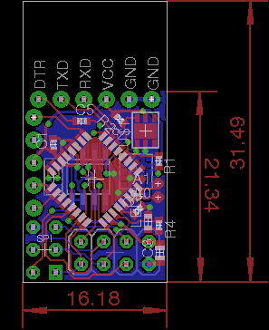
An update.. I got room for the ftdi header, as well as a 4pin header where I got power, and 3 digital IO (D3, D6 and D7, if I my memory serves me). Just need to find location for the last couple of tracks
Only detail though, is that I have gone with 0402 size smd components..
/ Thomas
-
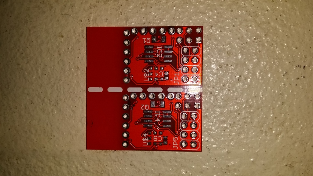
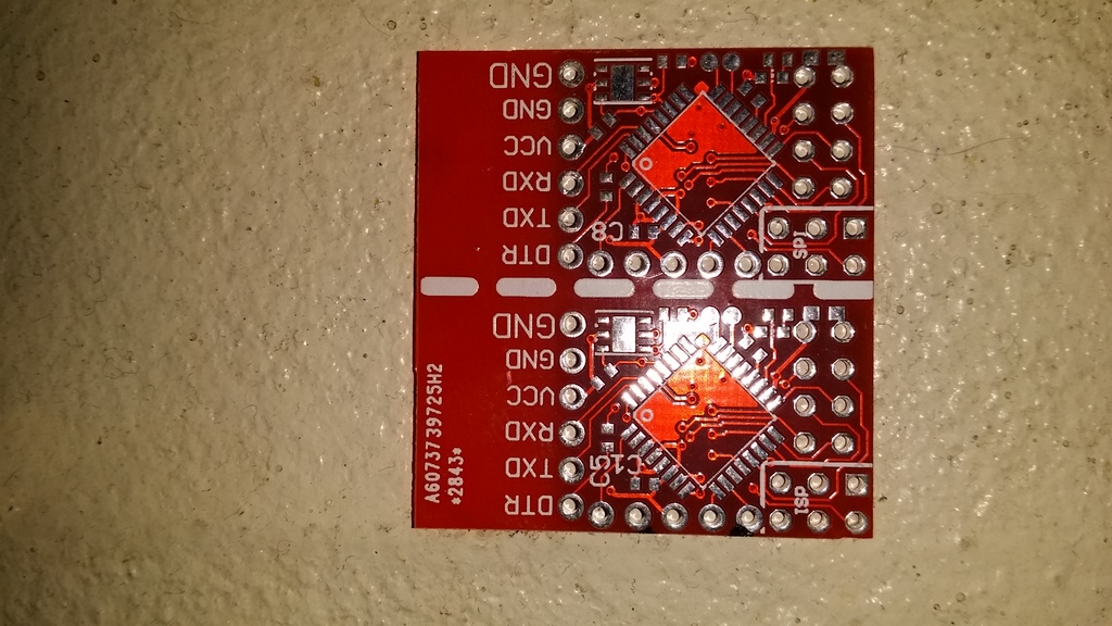
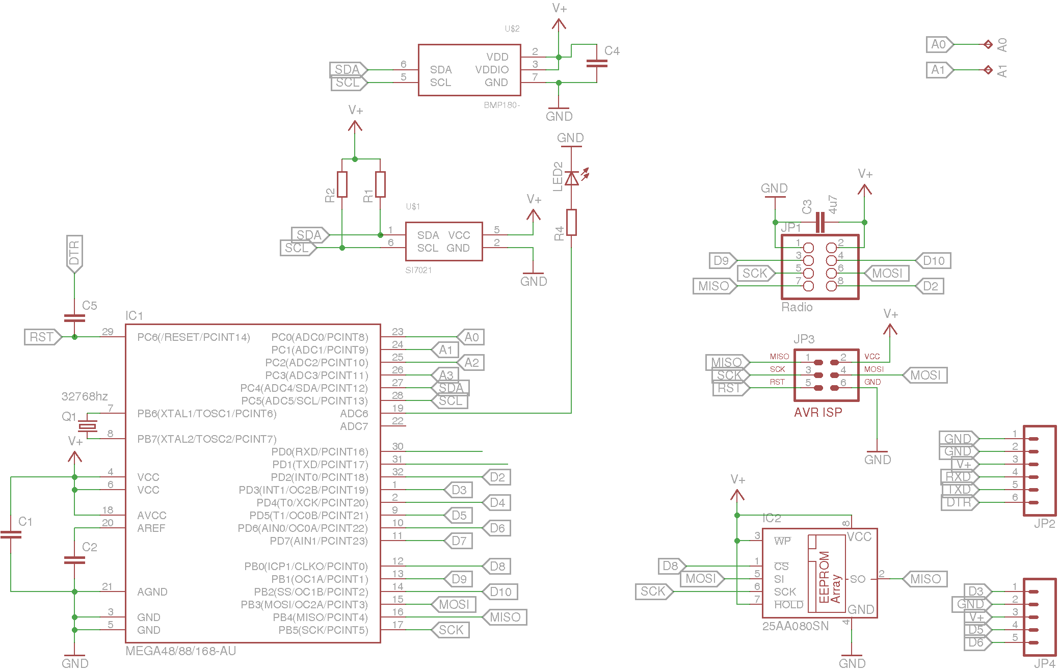
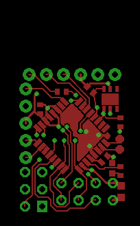
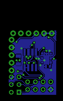
And the latest schematic, and layout (After I scratched the old routing, and started all over, again, for the 5th time I think :))
Actually I enjoy this fiddling with placing components, and routing tracks.. Only problem is that the wife thinks it takes too much time, and I should do other more usefull stuff, than playing with my computer, making noncense drawings :)
Schematics
full layout
top layer
bottom layer
Think I am ready to press the GO button for first spin in china.. This is gonna be exciting :)
-
And off they go to China.. Have ordered the first batch of prototypes.. (10 pcb's, panelized with 2 sensor boards per panel)
Now there is only the waiting time...
@tbowmo Amaons 2-day shipping has killed me. When I started with MySensors projects, and the China waiting time of sometimes 2-3 weeks.... Difficult haha.
-
Here it's more like 3-6 weeks waiting time, for stuff to come back from China.. So maybe it arrives in time for Christmas.. And then I can't get components sourced from mouser at that time (waiting until I have seen the quality of the boards, before I order components)
-
Haha!.. I have the same problem with the wife over here. The modules and half build sensors I spread all over the house is most irritating.
@hek, @tbowmo and rest: ho ho guys, first think WAF, ie Wife Acceptance Factor
This variable has to be VERY high. Like: Darling, this whole fidling of mine would optimize our home and save on energy bills big time, so You can spend more on shopping craze. etc :)
Probably when I finish with testing, I start selling it to friends and we will have problem spending all of the money which suddenly comes our way. (Try here not to laugh :) )
-
The reason why I am building this, is that I always have been currious about collecting data at regular intervals, back in the days (8-9 years ago) I had a setup with 5 DS18B20's on long wires arround the house. One was in my furnace measuring the temperature of the water, one was outside, etc. Everything connected to my old 486 based linux machine with 20Mb ram, collecting data from all the sensors on a regular interval, and presenting it with digitemp (a php package for displaying temperatures).
Just want to make something like that again. And I think my wife can see the ideas in it. Will just use it for environmental measurements throughout the house. Maybe some of them coupled to a SMS gateway, letting the teenagers know when to open up a window for 5 minutes, in order to get fresh air in, and the humidity level down. (And another SMS to remind them to shut the windows again).
And then the fun in collecting data, analyzing it in graphs etc... :)
-
@tbowmo I also have some old programmers including jtagice3 and can well understand you)
and sure, your very small design is best to keepThe only problem I have to use jtagice3 (which I like a lot to do hardware debugging) is that Arduino is not supported by hardware debugging
Just an idea - if you have all pins needed for FTDI programming on the corner later you can have a special connector between your board and FTDI programmer. This case you can keep design without extra space needed
sense and drive
-
@tbowmo I also have some old programmers including jtagice3 and can well understand you)
and sure, your very small design is best to keepThe only problem I have to use jtagice3 (which I like a lot to do hardware debugging) is that Arduino is not supported by hardware debugging
Just an idea - if you have all pins needed for FTDI programming on the corner later you can have a special connector between your board and FTDI programmer. This case you can keep design without extra space needed
@axillent said:
The only problem I have to use jtagice3 (which I like a lot to do hardware debugging) is that Arduino is not supported by hardware debugging
Wouldn't using jtagice3 for debugging also collide with the radio on a mysensor module?
Just an idea - if you have all pins needed for FTDI programming on the corner later you can have a special connector between your board and FTDI programmer. This case you can keep design without extra space needed
There is a full ftdi header on my board now. And I just got information from China that my boards are shipped... so just waiting for them to arrive now :)
-
@tbowmo said:
Wouldn't using jtagice3 for debugging also collide with the radio on a mysensor module?
jtagice3 is using only single pin of atmega328p (RESET pin) to do programming and debugging.There is no reason to have conflict with radio.
The only problem with jtagice3 is that arduino environment is not supporting hardware debugging.
I'm wondering on having ability to compile Mysensors using regular Atmel Astudio to be able to use debugging.There is a full ftdi header on my board now. And I just got information from China that my boards are shipped... so just waiting for them to arrive now :)
Cool! I also like 0603 footprints. But also is fine to use 0402. Sometimes you will probably need it.
If you need support I can prepare a bootloader for you with needed settings for boards.txtsense and drive
-
@tbowmo said:
Wouldn't using jtagice3 for debugging also collide with the radio on a mysensor module?
jtagice3 is using only single pin of atmega328p (RESET pin) to do programming and debugging.There is no reason to have conflict with radio.
The only problem with jtagice3 is that arduino environment is not supporting hardware debugging.
I'm wondering on having ability to compile Mysensors using regular Atmel Astudio to be able to use debugging.There is a full ftdi header on my board now. And I just got information from China that my boards are shipped... so just waiting for them to arrive now :)
Cool! I also like 0603 footprints. But also is fine to use 0402. Sometimes you will probably need it.
If you need support I can prepare a bootloader for you with needed settings for boards.txt@axillent said:
@tbowmo said:
Wouldn't using jtagice3 for debugging also collide with the radio on a mysensor module?
jtagice3 is using only single pin of atmega328p (RESET pin) to do programming and debugging.
Aaahh, yeah, I forgot about their "new" debugWire interface, so thought that a fullblown spi interface was nescessary for the ISP to program the device. Hmm.. With THAT info, I could have used a smaller pinheader, instead of the 6pin ISP header..
Could become handy for next revision of the board (if there'll be anny)
There is no reason to have conflict with radio.
The only problem with jtagice3 is that arduino environment is not supporting hardware debugging.
I'm wondering on having ability to compile Mysensors using regular Atmel Astudio to be able to use debugging.There is a full ftdi header on my board now. And I just got information from China that my boards are shipped... so just waiting for them to arrive now :)
Cool! I also like 0603 footprints. But also is fine to use 0402. Sometimes you will probably need it.
If you need support I can prepare a bootloader for you with needed settings for boards.txtI'm used to the small components.. And for a couple of handbuild sensor boards, I thought that I might as well cope with them, in order to keep the layout small :) If this is becomming a success, and others would like similair boards, the boards should be assembled with an pick & place machine, and then it doesn't matter that the components are 0402.
I'll keep it in mind with the bootloader :)
-
@axillent said:
@tbowmo said:
Wouldn't using jtagice3 for debugging also collide with the radio on a mysensor module?
jtagice3 is using only single pin of atmega328p (RESET pin) to do programming and debugging.
Aaahh, yeah, I forgot about their "new" debugWire interface, so thought that a fullblown spi interface was nescessary for the ISP to program the device. Hmm.. With THAT info, I could have used a smaller pinheader, instead of the 6pin ISP header..
Could become handy for next revision of the board (if there'll be anny)
There is no reason to have conflict with radio.
The only problem with jtagice3 is that arduino environment is not supporting hardware debugging.
I'm wondering on having ability to compile Mysensors using regular Atmel Astudio to be able to use debugging.There is a full ftdi header on my board now. And I just got information from China that my boards are shipped... so just waiting for them to arrive now :)
Cool! I also like 0603 footprints. But also is fine to use 0402. Sometimes you will probably need it.
If you need support I can prepare a bootloader for you with needed settings for boards.txtI'm used to the small components.. And for a couple of handbuild sensor boards, I thought that I might as well cope with them, in order to keep the layout small :) If this is becomming a success, and others would like similair boards, the boards should be assembled with an pick & place machine, and then it doesn't matter that the components are 0402.
I'll keep it in mind with the bootloader :)
@tbowmo said:
With THAT info, I could have used a smaller pinheader, instead of the 6pin ISP header..you cannot remove ISP header because debugWire is activated through ISP )))
@tbowmo said:
I'm used to the small components.. And for a couple of handbuild sensor boards, I thought that I might as well cope with them, in order to keep the layout small :) If this is becomming a success, and others would like similair boards, the boards should be assembled with an pick & place machine, and then it doesn't matter that the components are 0402.
Me and Henrik we have a list of partners for PCB production, If you fine to cooperate more closer with Mysensors we can help you on putting the board unto production. Just let Henrik to know if you have an interest on closer cooperation. I will help with production.
sense and drive
-
@tbowmo said:
With THAT info, I could have used a smaller pinheader, instead of the 6pin ISP header..you cannot remove ISP header because debugWire is activated through ISP )))
@tbowmo said:
I'm used to the small components.. And for a couple of handbuild sensor boards, I thought that I might as well cope with them, in order to keep the layout small :) If this is becomming a success, and others would like similair boards, the boards should be assembled with an pick & place machine, and then it doesn't matter that the components are 0402.
Me and Henrik we have a list of partners for PCB production, If you fine to cooperate more closer with Mysensors we can help you on putting the board unto production. Just let Henrik to know if you have an interest on closer cooperation. I will help with production.
@axillent said:
Me and Henrik we have a list of partners for PCB production, If you fine to cooperate more closer with Mysensors we can help you on putting the board unto production. Just let Henrik to know if you have an interest on closer cooperation. I will help with production.
I know, I have been talking with Henrik about it. Waiting for the first prototypes, so the design can be validated.
-
And the latest schematic, and layout (After I scratched the old routing, and started all over, again, for the 5th time I think :))
Actually I enjoy this fiddling with placing components, and routing tracks.. Only problem is that the wife thinks it takes too much time, and I should do other more usefull stuff, than playing with my computer, making noncense drawings :)
Schematics
full layout
top layer
bottom layer
Think I am ready to press the GO button for first spin in china.. This is gonna be exciting :)
-
I have been looking at prices (Using mouser, as they appear to have local european storage, so I can avoid import taxes in Denmark).
for a temperature / humidity sensor pcb, fully mounted, the price comes up to arround 13$ per unit. The most expensive part is the Si7021, which accounts for 4.5$ per unit (even in larger quantities).
for BMP180 on board, it's another 4.5$ added.
The above prices are material only...
@tbowmo Too bad the Si7021 is still too new to show up on AliExpress. The BMP180 is like $1.5 ... ironically the complete soldered module is also $1.5 ... Chinese economy ...
Component sourcing is the killer of fun things.
Hmmm. Am I correct to assume then that Mouser has free shipping over €65, and that they add country taxes on top? When I check out I seem to get a 25% VAT charge for instance. Ugh. Still better than paying an extra €10+ to the Swedish Post or UPS or whoever.
-
Hmm.. I don't trust aliexpress that much, for example is the BMP180 you get there a counterfeit?
Take the bmp180, I only need 1 of those, for the whole installation, so I don't mind paying 4-5$ more for a single unit. However, for the rest of the units, all needs the Si7021 (which is pin compatible with HTU21x device, if I remember correctly? However, the specs for the Si7021 is way better)
I don't know about the taxes from mouser, as I haven't actually bought anything there yet, only set up my project, and added the components needed, so I could get a price indicator on it. But their website says that they pays import duties etc..