💬 Ikea Molgan Hack
-
I measured with the new molgan and got nearly the same results. Perhaps my cheap multimeter isn't accurate enough though.
I moved the mysensor pcb to the new molgan pcb and tried this out. Strange result: at first it only send the initial messages but no triggers. After some minutes the opposite happened: it started to randomly trigger (or at least send them). Then after some more time the random triggers stopped and now its working as intended.
Perhaps it just the setup time of the PIR or the warmer air coming from a heater nearby... I will keep an eye on it the next days. -
Ok I did some more testing and the error seems to be pretty random. Sometimes the PIR works as intended for some time, sometimes it just keeps triggering constantly. I am pretty sure sleeping/waking up or sending the message is somehow influencing the PIR (don't know what else it could be).
Does anyone have an idea how to fix this (some wait() code or some cap somewhere perhaps)? -
i've not looked at the molgan..but for fixing this:
- if capa to place, that would be directly to the PIR sensor VCC pin (100uf), ideally close to it.
- or by software : ignoring false triggers, or disable the irq when it's not needed, or slow down a little bit clock during these false trigger.
-
@scalz and @gohan thank you very much! I added a 47uF electrolytic cap which helped a little. Afterwards I also added another 22nF ceramic cap. After that it seems to working just fine (for about 2 days now).
@Yveaux perhaps you could create a new version including some caps to fix this problem for anyone? I am still glad to finally be able to use this good looking cheap sensor. Thanks again for your work -
@scalz and @gohan thank you very much! I added a 47uF electrolytic cap which helped a little. Afterwards I also added another 22nF ceramic cap. After that it seems to working just fine (for about 2 days now).
@Yveaux perhaps you could create a new version including some caps to fix this problem for anyone? I am still glad to finally be able to use this good looking cheap sensor. Thanks again for your work@LastSamurai Great to hear it runs stable so far!
As I understood the capacitor is placed on the Molgan PCB, and that's a PCB I cannot redesign...
Where execactly did you plave the capacitor? Could you post a picture, so I can add it as a hint to the build guide. -
As the Molgan PCB works fine without the addon PCB it has to be its "fault" so I guess it makes sense to add them there. I placed the caps between GND and VCC of your pcb (which is linked to the molgan pcb). I also noticed that your pcb doesn't have any caps at the radio (right?). Normally you would add a 47uF caps there. Might that be part of the problem?
Here is a quick picture. I can take a better one later.
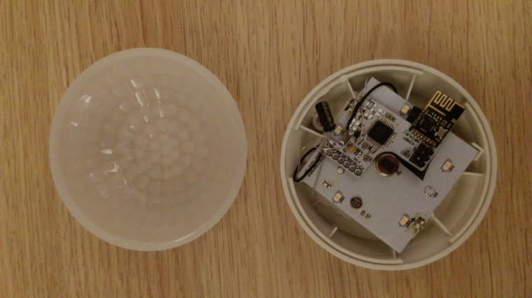
-
As the Molgan PCB works fine without the addon PCB it has to be its "fault" so I guess it makes sense to add them there. I placed the caps between GND and VCC of your pcb (which is linked to the molgan pcb). I also noticed that your pcb doesn't have any caps at the radio (right?). Normally you would add a 47uF caps there. Might that be part of the problem?
Here is a quick picture. I can take a better one later.
@LastSamurai said in 💬 Ikea Molgan Hack:
As the Molgan PCB works fine without the addon PCB it has to be its "fault" so I guess it makes sense to add them there. I placed the caps between GND and VCC of your pcb (which is linked to the molgan pcb).
Well, not too sure about that. In your case the PIR seems to suffer from disturbances introduced by the addon board (quick conclusion), so I would try to buffer there.
The PIR seems already buffered at two places (red & green caps):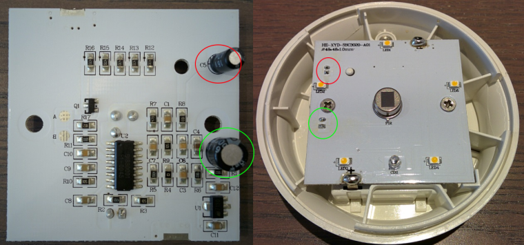
Adding an extra cap in parallel to the existing one(s) on the PIR-side of the PCB could be a simple solution.
I have to dive into the Molgan's PCB layout to see if that's possible.I also noticed that your pcb doesn't have any caps at the radio (right?). Normally you would add a 47uF caps there. Might that be part of the problem?
The radio has 100nF for decoupling on its own PCB.
I never mount a 47uF buffering cap (or some similar value) for battery powered sensors. -
I still have the second molgan on my desk waiting to be finished. I will experiment with that one adding caps in parallel to the once you marked and/or adding one directly across the +/- pads.
-
So I finally came around to testing with the second molgan. I put a small 22nF cap in parallel to the (in your picture) red cap on the board just on the backside of it. I also added a bigger 47uF electorlytic cap to the green one.
I have only had it running for about a day now and it helped at least partly. It doesn't seem to get into constantly triggering anymore (although this only happened after longer periods of time with the other one) but I still get multiple triggers every time. If I shortly move inside the range I get 2-3 triggers (30s pause). So I guess the problem isn't fixed yet. I will wait some time to see how this works out and then try to add a cap between the + and - pads of the pcb.Any other ideas? (Btw I find it strange that its working for you without any problems while I have the same problem with bost molgans)
@LastSamurai said in 💬 Ikea Molgan Hack:
I find it strange that its working for you without any problems while I have the same problem with bost molgans
I'm sorry that you're experiencing problems, but mine are running rock solid for months. Maybe there's variation in the Molgans produced by Ikea?
What PIR's do yours have? Mine are marked "PIR D203B" on top.I do have some issues with an outdoor D-SUN HC-SR501 based sensor.
This node starts to produce random bursts of triggers every now and then, which I tried to fix by replacing every part of the sensor.
After help from @scalz I found out the 47uF capacitor C102 (see schematics below, supposedly the schematic of the HC-SR501 from http://www.electrodragon.com/w/PIR_sensor) was only 100nF.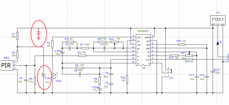
I replaced C102 with 100uF and added an extra cap to GND (connected to R1), to stabalize the power to the PIR.
First results show it runs stable, but time will have to tell if it keeps running that way.Maybe the Molgan also contains some cost reductions (like replacing C102 by 100nF).
To know for sure the schematic of the Molgan has to be known first... Any volunteers? -
I just spend an hour tracing the routes on the pcb. I am pretty sure I missed some (and there might be some errors) but here are my results for now. Ill redo them with KiCad later. Can someone measure the capacitors? They are unlabeled.
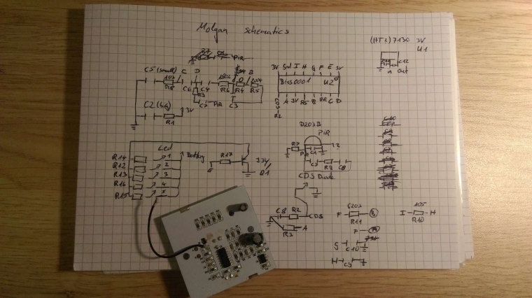
-
@LastSamurai
i already said it but you can try to solder a capa (100uf) to the Drain "Vcc" pin and the GND pin of the PIR sensor itself.
Maybe you could tweak R9 on your schema, even if i don't think it's exactly connected like this in real.
Why?
Combined with the resistor, the capa does filtering and buffering/storing energy.
You can find infos on google, this is about the capacitor RC time constant.
So, increasing res&capacitor value, you will increase the time it takes for charging capacitor (so the time to settle the PIR at startup), and what you want, it will take more time to discharge, regarding for example power consumption spikes etc..
Ideally, it gives better result by using the right resistor, but if you're not sure about the resistor and the schematic, easy route is to increase the capa like i said. At the right place, the sensor ic, also easier because it's through hole . Molgan board was not created for handling another circuit i think, so the hack. -
@scalz Yes, I am pretty sure the part of my schematics around the pir isn't complete yet.
I'll try the capacitor. Does it have to be the 100uF value? Atm I only have a 47uF cap that might be small enough to fit under the pcb. -
you can try, that could help, sure.
-
@GertSanders Awesome! Thanks for the tip man!
@Yveaux - Get yourself on the adafruit show and tell series dude! I for one, watch this series with intent to learn and discover new devices and how to recreate them for myself. I'm pretty sure that most of the audience that join into those are there for the same reason as me. Congrats on making it to their site full stop though :)
-
@Yveaux - Get yourself on the adafruit show and tell series dude! I for one, watch this series with intent to learn and discover new devices and how to recreate them for myself. I'm pretty sure that most of the audience that join into those are there for the same reason as me. Congrats on making it to their site full stop though :)
@Samuel235 said in 💬 Ikea Molgan Hack:
Get yourself on the adafruit show and tell series dude!
Which episode? I normally don't watch them :satisfied:
-
@Samuel235 said in 💬 Ikea Molgan Hack:
Get yourself on the adafruit show and tell series dude!
Which episode? I normally don't watch them :satisfied:
@Yveaux - This is the series that i'm talking about https://www.youtube.com/watch?v=lrcNW2MaelM&list=PL7E1FAA9E63A32FDC
They just have random people on video link talking about their products. Might even get some more interest into the MySensors movement let alone your own hardware. Its your choice on what product to get on there i suppose :)
They normally give you a slot on their air time to just explain your product - not sure how you get on though, application maybe? Let us know if you decide to go for it!
Check out their other series, something else may be more interest to your hardware or personal interest.
-
@Yveaux - This is the series that i'm talking about https://www.youtube.com/watch?v=lrcNW2MaelM&list=PL7E1FAA9E63A32FDC
They just have random people on video link talking about their products. Might even get some more interest into the MySensors movement let alone your own hardware. Its your choice on what product to get on there i suppose :)
They normally give you a slot on their air time to just explain your product - not sure how you get on though, application maybe? Let us know if you decide to go for it!
Check out their other series, something else may be more interest to your hardware or personal interest.
@Samuel235 Ah, I misunderstood; thought it was featured on the series already :see_no_evil:
Anyway, today my outside sensor felt like proving I didn't fix its issues yet:
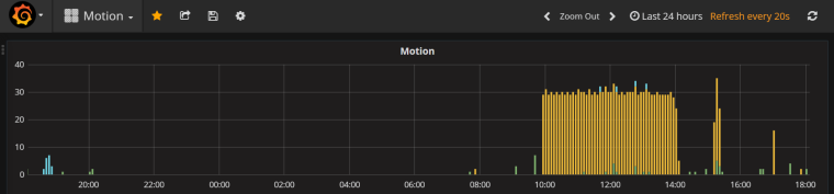
The yellow spikes is one continuous burst of roughly 4 hours in which it continuously triggers. After that it resumes normal operation...
Again, not a Molgan but an HC-SR501. However electronics are comparable. -
Thanks @Yveaux for the Molgan Hack board. I was my first experience in soldering an smd atmega ;-) Conclusion... need some more exercise. Finally got the thing working and now ready for the next steps. Some considerations:
- The PIR is very sensitive to power fluctuations. Voltages below 3.1V will certainly cause instability.
- I want to keep the light feature of the Molgan but make it accessible from MySensors. Same with the light sensor.
- Power the Molgan with low selfdischarge rechargeable batteries (The led's will drain the batteries faster)
- Maybe add a few other sensors (temp/ hum/ light effects)
With the help of the excellent analysis work of @LastSamurai I'm thinking of the following "Ikea Molgan Hack Hacks"
- add a 3.3V ldo (XC6206, 1uA ldd, 0.08V dropout) to power the Hack board and sensors.
- a voltage divider for measuring real battery voltage.
- drive the Led's from a pwm output on the base of transistor connected to R17
- Measure the photodiode voltage one way or another.
- breakout the SCL and SDA pins for more sensors.
Any suggestions? (for sure a breadboarding exercise)
Hello! It looks like you're interested in this conversation, but you don't have an account yet.
Getting fed up of having to scroll through the same posts each visit? When you register for an account, you'll always come back to exactly where you were before, and choose to be notified of new replies (either via email, or push notification). You'll also be able to save bookmarks and upvote posts to show your appreciation to other community members.
With your input, this post could be even better 💗
Register Login