MYSBootloader 1.3.0-beta.3
-
@Werwolfx As soon as the bootloader takes over, in your case after the reboot request (1), but before the MYS lib 2.1.0 init message (2):
(1) 14.01.2017 11:38:03 TX  4;0;3;0;13;0
(2) 14.01.2017 11:38:09 RX  4;255;0;0;17;2.1.0
it will send a I_FIRMWARE_CONFIG_REQUEST message to inform the controller about the currently loaded FW and request a new FW.
looks like this:
4;255;4;0;0;BE0001003003D8490102This is missing in your case, therefore I'm wondering if you have incompatible radio settings. Please post your GW sketch and upload your MYSBootloader.hex file for further troubleshooting.
@tekka GW on esp8266 (default sketch) + NRF24L01+
on GW/** * The MySensors Arduino library handles the wireless radio link and protocol * between your home built sensors/actuators and HA controller of choice. * The sensors forms a self healing radio network with optional repeaters. Each * repeater and gateway builds a routing tables in EEPROM which keeps track of the * network topology allowing messages to be routed to nodes. * * Created by Henrik Ekblad <henrik.ekblad@mysensors.org> * Copyright (C) 2013-2015 Sensnology AB * Full contributor list: https://github.com/mysensors/Arduino/graphs/contributors * * Documentation: http://www.mysensors.org * Support Forum: http://forum.mysensors.org * * This program is free software; you can redistribute it and/or * modify it under the terms of the GNU General Public License * version 2 as published by the Free Software Foundation. * ******************************* * * REVISION HISTORY * Version 1.0 - Henrik EKblad * Contribution by a-lurker and Anticimex, * Contribution by Norbert Truchsess <norbert.truchsess@t-online.de> * Contribution by Ivo Pullens (ESP8266 support) * * DESCRIPTION * The EthernetGateway sends data received from sensors to the WiFi link. * The gateway also accepts input on ethernet interface, which is then sent out to the radio network. * * VERA CONFIGURATION: * Enter "ip-number:port" in the ip-field of the Arduino GW device. This will temporarily override any serial configuration for the Vera plugin. * E.g. If you want to use the defualt values in this sketch enter: 192.168.178.66:5003 * * LED purposes: * - To use the feature, uncomment any of the MY_DEFAULT_xx_LED_PINs in your sketch, only the LEDs that is defined is used. * - RX (green) - blink fast on radio message recieved. In inclusion mode will blink fast only on presentation recieved * - TX (yellow) - blink fast on radio message transmitted. In inclusion mode will blink slowly * - ERR (red) - fast blink on error during transmission error or recieve crc error * * See http://www.mysensors.org/build/esp8266_gateway for wiring instructions. * nRF24L01+ ESP8266 * VCC VCC * CE GPIO4 * CSN/CS GPIO15 * SCK GPIO14 * MISO GPIO12 * MOSI GPIO13 * GND GND * * Not all ESP8266 modules have all pins available on their external interface. * This code has been tested on an ESP-12 module. * The ESP8266 requires a certain pin configuration to download code, and another one to run code: * - Connect REST (reset) via 10K pullup resistor to VCC, and via switch to GND ('reset switch') * - Connect GPIO15 via 10K pulldown resistor to GND * - Connect CH_PD via 10K resistor to VCC * - Connect GPIO2 via 10K resistor to VCC * - Connect GPIO0 via 10K resistor to VCC, and via switch to GND ('bootload switch') * * Inclusion mode button: * - Connect GPIO5 via switch to GND ('inclusion switch') * * Hardware SHA204 signing is currently not supported! * * Make sure to fill in your ssid and WiFi password below for ssid & pass. */ // Enable debug prints to serial monitor #define MY_DEBUG // Use a bit lower baudrate for serial prints on ESP8266 than default in MyConfig.h #define MY_BAUD_RATE 115200 // Enables and select radio type (if attached) #define MY_RADIO_NRF24 //#define MY_RADIO_RFM69 #define MY_GATEWAY_ESP8266 #define MY_ESP8266_SSID "WiFI" #define MY_ESP8266_PASSWORD "password[0_1484386469111_MYSBootloader.hex](/uploads/files/1484386469171-mysbootloader.hex) " // Enable UDP communication //#define MY_USE_UDP // Set the hostname for the WiFi Client. This is the hostname // it will pass to the DHCP server if not static. // #define MY_ESP8266_HOSTNAME "sensor-gateway" // Enable MY_IP_ADDRESS here if you want a static ip address (no DHCP) //#define MY_IP_ADDRESS 192,168,178,87 // If using static ip you need to define Gateway and Subnet address as well //#define MY_IP_GATEWAY_ADDRESS 192,168,178,1 //#define MY_IP_SUBNET_ADDRESS 255,255,255,0 // The port to keep open on node server mode #define MY_PORT 5003 // How many clients should be able to connect to this gateway (default 1) #define MY_GATEWAY_MAX_CLIENTS 2 // Controller ip address. Enables client mode (default is "server" mode). // Also enable this if MY_USE_UDP is used and you want sensor data sent somewhere. //#define MY_CONTROLLER_IP_ADDRESS 192, 168, 178, 68 // Enable inclusion mode #define MY_INCLUSION_MODE_FEATURE // Enable Inclusion mode button on gateway // #define MY_INCLUSION_BUTTON_FEATURE // Set inclusion mode duration (in seconds) #define MY_INCLUSION_MODE_DURATION 60 // Digital pin used for inclusion mode button #define MY_INCLUSION_MODE_BUTTON_PIN 3 // Set blinking period // #define MY_DEFAULT_LED_BLINK_PERIOD 300 // Flash leds on rx/tx/err // Led pins used if blinking feature is enabled above #define MY_DEFAULT_ERR_LED_PIN 16 // Error led pin #define MY_DEFAULT_RX_LED_PIN 16 // Receive led pin #define MY_DEFAULT_TX_LED_PIN 16 // the PCB, on board LED #if defined(MY_USE_UDP) #include <WiFiUdp.h> #endif #include <ESP8266WiFi.h> #include <MySensors.h> void setup() { } void presentation() { // Present locally attached sensors here } void loop() { // Send locally attached sensors data here }In MYSController on mudule i click INFO
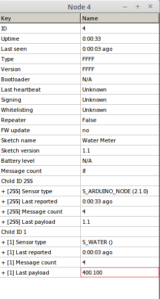
FW Update = no
Bootloader = N/Amay be problem in the Bootloader.hex?
-
@tekka GW on esp8266 (default sketch) + NRF24L01+
on GW/** * The MySensors Arduino library handles the wireless radio link and protocol * between your home built sensors/actuators and HA controller of choice. * The sensors forms a self healing radio network with optional repeaters. Each * repeater and gateway builds a routing tables in EEPROM which keeps track of the * network topology allowing messages to be routed to nodes. * * Created by Henrik Ekblad <henrik.ekblad@mysensors.org> * Copyright (C) 2013-2015 Sensnology AB * Full contributor list: https://github.com/mysensors/Arduino/graphs/contributors * * Documentation: http://www.mysensors.org * Support Forum: http://forum.mysensors.org * * This program is free software; you can redistribute it and/or * modify it under the terms of the GNU General Public License * version 2 as published by the Free Software Foundation. * ******************************* * * REVISION HISTORY * Version 1.0 - Henrik EKblad * Contribution by a-lurker and Anticimex, * Contribution by Norbert Truchsess <norbert.truchsess@t-online.de> * Contribution by Ivo Pullens (ESP8266 support) * * DESCRIPTION * The EthernetGateway sends data received from sensors to the WiFi link. * The gateway also accepts input on ethernet interface, which is then sent out to the radio network. * * VERA CONFIGURATION: * Enter "ip-number:port" in the ip-field of the Arduino GW device. This will temporarily override any serial configuration for the Vera plugin. * E.g. If you want to use the defualt values in this sketch enter: 192.168.178.66:5003 * * LED purposes: * - To use the feature, uncomment any of the MY_DEFAULT_xx_LED_PINs in your sketch, only the LEDs that is defined is used. * - RX (green) - blink fast on radio message recieved. In inclusion mode will blink fast only on presentation recieved * - TX (yellow) - blink fast on radio message transmitted. In inclusion mode will blink slowly * - ERR (red) - fast blink on error during transmission error or recieve crc error * * See http://www.mysensors.org/build/esp8266_gateway for wiring instructions. * nRF24L01+ ESP8266 * VCC VCC * CE GPIO4 * CSN/CS GPIO15 * SCK GPIO14 * MISO GPIO12 * MOSI GPIO13 * GND GND * * Not all ESP8266 modules have all pins available on their external interface. * This code has been tested on an ESP-12 module. * The ESP8266 requires a certain pin configuration to download code, and another one to run code: * - Connect REST (reset) via 10K pullup resistor to VCC, and via switch to GND ('reset switch') * - Connect GPIO15 via 10K pulldown resistor to GND * - Connect CH_PD via 10K resistor to VCC * - Connect GPIO2 via 10K resistor to VCC * - Connect GPIO0 via 10K resistor to VCC, and via switch to GND ('bootload switch') * * Inclusion mode button: * - Connect GPIO5 via switch to GND ('inclusion switch') * * Hardware SHA204 signing is currently not supported! * * Make sure to fill in your ssid and WiFi password below for ssid & pass. */ // Enable debug prints to serial monitor #define MY_DEBUG // Use a bit lower baudrate for serial prints on ESP8266 than default in MyConfig.h #define MY_BAUD_RATE 115200 // Enables and select radio type (if attached) #define MY_RADIO_NRF24 //#define MY_RADIO_RFM69 #define MY_GATEWAY_ESP8266 #define MY_ESP8266_SSID "WiFI" #define MY_ESP8266_PASSWORD "password[0_1484386469111_MYSBootloader.hex](/uploads/files/1484386469171-mysbootloader.hex) " // Enable UDP communication //#define MY_USE_UDP // Set the hostname for the WiFi Client. This is the hostname // it will pass to the DHCP server if not static. // #define MY_ESP8266_HOSTNAME "sensor-gateway" // Enable MY_IP_ADDRESS here if you want a static ip address (no DHCP) //#define MY_IP_ADDRESS 192,168,178,87 // If using static ip you need to define Gateway and Subnet address as well //#define MY_IP_GATEWAY_ADDRESS 192,168,178,1 //#define MY_IP_SUBNET_ADDRESS 255,255,255,0 // The port to keep open on node server mode #define MY_PORT 5003 // How many clients should be able to connect to this gateway (default 1) #define MY_GATEWAY_MAX_CLIENTS 2 // Controller ip address. Enables client mode (default is "server" mode). // Also enable this if MY_USE_UDP is used and you want sensor data sent somewhere. //#define MY_CONTROLLER_IP_ADDRESS 192, 168, 178, 68 // Enable inclusion mode #define MY_INCLUSION_MODE_FEATURE // Enable Inclusion mode button on gateway // #define MY_INCLUSION_BUTTON_FEATURE // Set inclusion mode duration (in seconds) #define MY_INCLUSION_MODE_DURATION 60 // Digital pin used for inclusion mode button #define MY_INCLUSION_MODE_BUTTON_PIN 3 // Set blinking period // #define MY_DEFAULT_LED_BLINK_PERIOD 300 // Flash leds on rx/tx/err // Led pins used if blinking feature is enabled above #define MY_DEFAULT_ERR_LED_PIN 16 // Error led pin #define MY_DEFAULT_RX_LED_PIN 16 // Receive led pin #define MY_DEFAULT_TX_LED_PIN 16 // the PCB, on board LED #if defined(MY_USE_UDP) #include <WiFiUdp.h> #endif #include <ESP8266WiFi.h> #include <MySensors.h> void setup() { } void presentation() { // Present locally attached sensors here } void loop() { // Send locally attached sensors data here }In MYSController on mudule i click INFO
FW Update = no
Bootloader = N/Amay be problem in the Bootloader.hex?
-
@tekka said:
@Werwolfx Please also update the bootloader file.
I'll update more than once, but there is no effect.
avrdude writes that everything is OK
I do not know what to do = (avrdude: AVR device initialized and ready to accept instructions Reading | ################################################## | 100% 0.00s avrdude: Device signature = 0x1e950f (probably m328p) avrdude: NOTE: "flash" memory has been specified, an erase cycle will be performed To disable this feature, specify the -D option. avrdude: erasing chip avrdude: auto set sck period (because given equals null) avrdude: warning: cannot set sck period. please check for usbasp firmware update. avrdude: reading input file "/media/werwolfx/SSDData/arduino-1.8.0/hardware/arduino/avr/bootloaders/MySensors/MYSBootloader.hex" avrdude: writing flash (32762 bytes): Writing | ################################################## | 100% 0.00s avrdude: 32762 bytes of flash written avrdude: verifying flash memory against /media/werwolfx/SSDData/arduino-1.8.0/hardware/arduino/avr/bootloaders/MySensors/MYSBootloader.hex: avrdude: load data flash data from input file /media/werwolfx/SSDData/arduino-1.8.0/hardware/arduino/avr/bootloaders/MySensors/MYSBootloader.hex: avrdude: input file /media/werwolfx/SSDData/arduino-1.8.0/hardware/arduino/avr/bootloaders/MySensors/MYSBootloader.hex contains 32762 bytes avrdude: reading on-chip flash data: Reading | ################################################## | 100% 0.00s avrdude: verifying ... avrdude: 32762 bytes of flash verified avrdude: reading input file "0x0F" avrdude: writing lock (1 bytes): Writing | ################################################## | 100% 0.01s avrdude: 1 bytes of lock written avrdude: verifying lock memory against 0x0F: avrdude: load data lock data from input file 0x0F: avrdude: input file 0x0F contains 1 bytes avrdude: reading on-chip lock data: Reading | ################################################## | 100% 0.00s avrdude: verifying ... avrdude: 1 bytes of lock verified avrdude done. Thank you. -
@tekka If i ENABLE #define MY_OTA_FIRMWARE_FEATURE
i see ST_FIRMWARE_CONFIG_REQUEST in MYSCONTROLLER logs!!!
if i DISABLE //#define MY_OTA_FIRMWARE_FEATURE msg not in logi not have external flash/
402	14.01.2017 21:29:28	TX	4 - Water Meter	N/A	C_INTERNAL	NO	I_REBOOT	0
403	14.01.2017 21:29:28	RX	4	1	C_REQ	NO	V_VAR1
408	14.01.2017 21:29:34	RX	4	INTERNAL	C_STREAM	NO	ST_FIRMWARE_CONFIG_REQUEST	FFFFFFFF48044E100300
409	14.01.2017 21:29:34	TX	4	N/A	C_STREAM	NO	ST_FIRMWARE_CONFIG_RESPONSE	0A0001005000D446
410	14.01.2017 21:29:34	RX	4	INTERNAL	C_PRESENTATION	NO	S_ARDUINO_NODE	2.1.0
411	14.01.2017 21:29:34	RX	4	INTERNAL	C_INTERNAL	NO	I_CONFIG	0
412	14.01.2017 21:29:34	TX	4	INTERNAL	C_INTERNAL	NO	I_CONFIG	M
414	14.01.2017 21:29:34	RX	4 - Water Meter	INTERNAL	C_INTERNAL	NO	I_SKETCH_NAME	Water Meter
417	14.01.2017 21:29:34	RX	4 - Water Meter	INTERNAL	C_INTERNAL	NO	I_SKETCH_VERSION	1.1
419	14.01.2017 21:29:34	RX	4 - Water Meter	1 - S_WATER	C_PRESENTATION	NO	S_WATER
i load this HEX
load from Arduino IDE 1.8.0
0_1484418874223_MYSBootloader.hexboard.txt
proMYSBL.bootloader.tool=avrdude
proMYSBL.bootloader.low_fuses=0xFF
proMYSBL.bootloader.high_fuses=0xDA
proMYSBL.bootloader.extended_fuses=0xFE
proMYSBL.bootloader.unlock_bits=0x3F
proMYSBL.bootloader.lock_bits=0x0F
proMYSBL.bootloader.file=MySensors/MYSBootloader.hex -
@tekka am I correct in thinking the HEX found on Github can be used with all Arduino's? I noticed my old folder has one hex for 16, 8 and 1Mhz?
I'm using this board.txt
menu.cpu=Processor ############################################################## MYSBL13.name=MYS Bootloader - atmega328p MYSBL13.upload.tool=arduino:avrdude MYSBL13.upload.protocol=arduino MYSBL13.upload.maximum_size=30720 MYSBL13.upload.maximum_data_size=2048 MYSBL13.bootloader.tool=arduino:avrdude MYSBL13.bootloader.unlock_bits=0x3F MYSBL13.bootloader.lock_bits=0x0F MYSBL13.build.mcu=atmega328p MYSBL13.build.board=AVR_PRO MYSBL13.build.core=arduino:arduino MYSBL13.build.variant=arduino:standard ## ------------------------------------------------- MYSBL13.menu.cpu.16MHzatmega328=ATmega328 16MHz (XTAL, BOD1V8) MYSBL13.menu.cpu.16MHzatmega328.upload.speed=115200 MYSBL13.menu.cpu.16MHzatmega328.bootloader.low_fuses=0xFF MYSBL13.menu.cpu.16MHzatmega328.bootloader.high_fuses=0xDA MYSBL13.menu.cpu.16MHzatmega328.bootloader.extended_fuses=0x06 MYSBL13.menu.cpu.16MHzatmega328.bootloader.file=MYSBootloader/MYSBootloader.hex MYSBL13.menu.cpu.16MHzatmega328.build.f_cpu=16000000L MYSBL13.menu.cpu.8MHzatmega328=ATmega328 8MHz (RC, BOD1V8) MYSBL13.menu.cpu.8MHzatmega328.upload.speed=38400 MYSBL13.menu.cpu.8MHzatmega328.bootloader.low_fuses=0xE2 MYSBL13.menu.cpu.8MHzatmega328.bootloader.high_fuses=0xDA MYSBL13.menu.cpu.8MHzatmega328.bootloader.extended_fuses=0x06 MYSBL13.menu.cpu.8MHzatmega328.bootloader.file=MYSBootloader/MYSBootloader.hex MYSBL13.menu.cpu.8MHzatmega328.build.f_cpu=8000000L MYSBL13.menu.cpu.1MHzatmega328=ATmega328 1MHz (RC/8, BOD1V8) MYSBL13.menu.cpu.1MHzatmega328.upload.speed=9600 MYSBL13.menu.cpu.1MHzatmega328.bootloader.low_fuses=0x62 MYSBL13.menu.cpu.1MHzatmega328.bootloader.high_fuses=0xDA MYSBL13.menu.cpu.1MHzatmega328.bootloader.extended_fuses=0x06 MYSBL13.menu.cpu.1MHzatmega328.bootloader.file=MYSBootloader/MYSBootloader.hex MYSBL13.menu.cpu.1MHzatmega328.build.f_cpu=1000000L``` -
I guess not... The old hex for 8Mhz works, but the one from this thread does not... :(
I'm trying to upload this to my Pro Mini, does anyone have an 8Mhz that works?
-
@tekka I've noticed some odd things with my nodes when running the bootloader.
To test I uploaded a simple count time sketch. When running the MYS bootloader the timer resets every 10 seconds, see:
Time: 999
Time: 2000
Time: 3000
Time: 4001
Time: 5001
Time: 6002
Time: 7004
Time: 8003
Time: 9005
Time: 0
Time: 999
Time: 2000
Time: 3000
Time: 4001
Time: 5001
Time: 6002
Time: 7004
Time: 8003
Time: 9005
Time: 0
Using the stock Pro Mim 8Mhz 3.3v bootloader it works fine, any ideas?
Perhaps this is because I'm testing using a non-MySensors sketch? -
@tekka, I'm trying to compile the HEX using OSX. I have installed avr-gcc with homebrew but I get
rm *.o
rm: *.o: No such file or directory
make: [clean] Error 1 (ignored)
rm *.elf
rm: *.elf: No such file or directory
make: [clean] Error 1 (ignored)
rm *.hex
rm: *.hex: No such file or directory
make: [clean] Error 1 (ignored)
"avr-gcc" -funsigned-char -funsigned-bitfields -DF_CPU=16000000L -Os -ffunction-sections -fdata-sections -fpack-struct -fshort-enums -mrelax -Wall -Wextra -Wundef -pedantic -mmcu=atmega328p -c -std=gnu99 -MD -MP -MF "MYSBootloader.d" -MT"MYSBootloader.d" -MT"MYSBootloader.o" -I MYSBootloader.c -o MYSBootloader.o
avr-gcc: fatal error: no input files
compilation terminated.
make: *** [MYSBootloader.o] Error 1When issueing the Make command, can you help, any suggestions?
-
@tekka, started a windows VM, run via MinGW and got this when running makefile, does it look okay?
C:\MySensorsBootloaderRF24-development>mingw32-make.exe rm *.o process_begin: CreateProcess(NULL, rm *.o, ...) failed. make (e=2): The system cannot find the file specified. Makefile:40: recipe for target 'clean' failed mingw32-make.exe: [clean] Error 2 (ignored) rm *.elf process_begin: CreateProcess(NULL, rm *.elf, ...) failed. make (e=2): The system cannot find the file specified. Makefile:40: recipe for target 'clean' failed mingw32-make.exe: [clean] Error 2 (ignored) rm *.hex process_begin: CreateProcess(NULL, rm *.hex, ...) failed. make (e=2): The system cannot find the file specified. Makefile:40: recipe for target 'clean' failed mingw32-make.exe: [clean] Error 2 (ignored) "C:/Arduino/hardware/tools/avr/bin/avr-gcc" -funsigned-char -funsigned-bitfields -DF_CPU=16000000L -Os -ffunction-sections -fdata-sections -fpack-struct -fshort -enums -mrelax -Wall -Wextra -Wundef -pedantic -mmcu=atmega328p -c -std=gnu99 -M D -MP -MF "MYSBootloader.d" -MT"MYSBootloader.d" -MT"MYSBootloader.o" -IC:/Ardu ino/hardware/tools/avr/avr/include/avr MYSBootloader.c -o MYSBootloader.o In file included from Core.h:40:0, from MYSBootloader.c:69: HW.h:51:2: warning: #warning is a GCC extension #warning BAUD_RATE error greater than 2% ^ HW.h:51:2: warning: #warning BAUD_RATE error greater than 2% [-Wcpp] In file included from Core.h:42:0, from MYSBootloader.c:69: MyMessage.h:292:3: warning: ISO C99 doesn't support unnamed structs/unions [-Wpe dantic] }; ^ "C:/Arduino/hardware/tools/avr/bin/avr-gcc" -nostartfiles -Wl,-s -Wl,-static -Wl ,-Map=".map" -Wl,--start-group -Wl,--end-group -Wl,--gc-sections -mrelax -Wl,-se ction-start=.text=0x7800 -mmcu=atmega328p -o MYSBootloader.elf MYSBootloader.o -lm "C:/Arduino/hardware/tools/avr/bin/avr-objcopy" -O ihex -R .eeprom MYSBootloader .elf MYSBootloader.hex "C:/Arduino/hardware/tools/avr/bin/avr-size" MYSBootloader.elf text data bss dec hex filename 2036 6 72 2114 842 MYSBootloader.elf -
@tekka Just wanted to check if the above log looks okay, currently rolling the bootloader out to 14 nodes (painful process!) and wanted to check if it looks okay before I do.
I'm also using this board.txt, I made a separate entry for my Uno's, do they all look okay? I basically used the fuses from the standard Arduino boards.txt with the change of 0x05 to 0x06 for the BOD? I noticed in the makefile that you can specify the fuses, do I need to compile a bootloader for each device with the exact fuses, or will one bootloader for 16 / 8 / 1Mhz suffice?
Thank you very much in advance, the bootloader is amazing work.
menu.cpu=Processor ############################################################## pro.name=MySensors Bootloader for Pro Mini pro.upload.tool=arduino:avrdude pro.upload.protocol=arduino pro.upload.maximum_size=30720 pro.upload.maximum_data_size=2048 pro.bootloader.tool=arduino:avrdude pro.bootloader.unlock_bits=0x3F pro.bootloader.lock_bits=0x0F pro.build.mcu=atmega328p pro.build.board=AVR_PRO pro.build.core=arduino:arduino pro.build.variant=arduino:standard ## Arduino with MYSBootloader Beta 2 ## ------------------------------------------------- ## pro.menu.cpu.16MHzatmega328=ATmega328 16MHz (XTAL, BOD1V8) 1.3 Beta 2 ## pro.menu.cpu.16MHzatmega328.upload.speed=115200 ## pro.menu.cpu.16MHzatmega328.bootloader.low_fuses=0xFF ## pro.menu.cpu.16MHzatmega328.bootloader.high_fuses=0xDA ## pro.menu.cpu.16MHzatmega328.bootloader.extended_fuses=0x06 ## pro.menu.cpu.16MHzatmega328.bootloader.file=MYSBootloader/MYSBootloader_B2_16Mhz.hex ## pro.menu.cpu.16MHzatmega328.build.f_cpu=16000000L ## pro.menu.cpu.8MHzatmega328=ATmega328 8MHz (RC, BOD1V8) 1.3 Beta 2 ## pro.menu.cpu.8MHzatmega328.upload.speed=38400 ## pro.menu.cpu.8MHzatmega328.bootloader.low_fuses=0xE2 ## pro.menu.cpu.8MHzatmega328.bootloader.high_fuses=0xDA ## pro.menu.cpu.8MHzatmega328.bootloader.extended_fuses=0x06 ## pro.menu.cpu.8MHzatmega328.bootloader.file=MYSBootloader/MYSBootloader_B2_8Mhz.hex ## pro.menu.cpu.8MHzatmega328.build.f_cpu=8000000L ## pro.menu.cpu.1MHzatmega328=ATmega328 1MHz (RC/8, BOD1V8) 1.3 Beta 2 ## pro.menu.cpu.1MHzatmega328.upload.speed=9600 ## pro.menu.cpu.1MHzatmega328.bootloader.low_fuses=0x62 ## pro.menu.cpu.1MHzatmega328.bootloader.high_fuses=0xDA ## pro.menu.cpu.1MHzatmega328.bootloader.extended_fuses=0x06 ## pro.menu.cpu.1MHzatmega328.bootloader.file=MYSBootloader/MYSBootloader_B2_1Mhz.hex ## pro.menu.cpu.1MHzatmega328.build.f_cpu=1000000L ## Arduino with MYSBootloader Beta 3 ## ------------------------------------------------- pro.menu.cpu.16MHzatmega328=ATmega328 16MHz (XTAL, BOD1V8) 1.3 Beta 3 pro.menu.cpu.16MHzatmega328.upload.speed=115200 pro.menu.cpu.16MHzatmega328.bootloader.low_fuses=0xFF pro.menu.cpu.16MHzatmega328.bootloader.high_fuses=0xDA pro.menu.cpu.16MHzatmega328.bootloader.extended_fuses=0x06 pro.menu.cpu.16MHzatmega328.bootloader.file=MYSBootloader/MYSBootloader_B3_16Mhz.hex pro.menu.cpu.16MHzatmega328.build.f_cpu=16000000L pro.menu.cpu.8MHzatmega328=ATmega328 8MHz (RC, BOD1V8) 1.3 Beta 3 pro.menu.cpu.8MHzatmega328.upload.speed=38400 pro.menu.cpu.8MHzatmega328.bootloader.low_fuses=0xFF pro.menu.cpu.8MHzatmega328.bootloader.high_fuses=0xDA pro.menu.cpu.8MHzatmega328.bootloader.extended_fuses=0x06 pro.menu.cpu.8MHzatmega328.bootloader.file=MYSBootloader/MYSBootloader_B3_8Mhz.hex pro.menu.cpu.8MHzatmega328.build.f_cpu=8000000L pro.menu.cpu.1MHzatmega328=ATmega328 1MHz (RC/8, BOD1V8) 1.3 Beta 3 pro.menu.cpu.1MHzatmega328.upload.speed=9600 pro.menu.cpu.1MHzatmega328.bootloader.low_fuses=0x62 pro.menu.cpu.1MHzatmega328.bootloader.high_fuses=0xDA pro.menu.cpu.1MHzatmega328.bootloader.extended_fuses=0x06 pro.menu.cpu.1MHzatmega328.bootloader.file=MYSBootloader/MYSBootloader_B3_1Mhz.hex pro.menu.cpu.1MHzatmega328.build.f_cpu=1000000L ############################################################## ############################################################## ############################################################## ############################################################## ############################################################## menu.cpu=Processor ############################################################## uno.name=MySensors Bootloader for Uno uno.upload.tool=arduino:avrdude uno.upload.protocol=arduino uno.upload.maximum_size=32256 uno.upload.maximum_data_size=2048 uno.bootloader.tool=arduino:avrdude uno.bootloader.unlock_bits=0x3F uno.bootloader.lock_bits=0x0F uno.build.mcu=atmega328p uno.build.board=AVR_UNO uno.build.core=arduino:arduino uno.build.variant=arduino:standard ## Arduino with MYSBootloader Beta 2 ## ------------------------------------------------- ## uno.menu.cpu.16MHzatmega328=ATmega328 16MHz (XTAL, BOD1V8) 1.3 Beta 2 ## uno.menu.cpu.16MHzatmega328.upload.speed=115200 ## uno.menu.cpu.16MHzatmega328.bootloader.low_fuses=0xFF ## uno.menu.cpu.16MHzatmega328.bootloader.high_fuses=0xDA ## uno.menu.cpu.16MHzatmega328.bootloader.extended_fuses=0x06 ## uno.menu.cpu.16MHzatmega328.bootloader.file=MYSBootloader/MYSBootloader_B2_16Mhz.hex ## uno.menu.cpu.16MHzatmega328.build.f_cpu=16000000L ## Arduino with MYSBootloader Beta 3 ## ------------------------------------------------- uno.menu.cpu.16MHzatmega328=ATmega328 16MHz (XTAL, BOD1V8) 1.3 Beta 3 uno.menu.cpu.16MHzatmega328.upload.speed=115200 uno.menu.cpu.16MHzatmega328.bootloader.low_fuses=0xFF uno.menu.cpu.16MHzatmega328.bootloader.high_fuses=0xDA uno.menu.cpu.16MHzatmega328.bootloader.extended_fuses=0x06 uno.menu.cpu.16MHzatmega328.bootloader.file=MYSBootloader/MYSBootloader_B3_16Mhz.hex uno.menu.cpu.16MHzatmega328.build.f_cpu=16000000L -
@tekka, started a windows VM, run via MinGW and got this when running makefile, does it look okay?
C:\MySensorsBootloaderRF24-development>mingw32-make.exe rm *.o process_begin: CreateProcess(NULL, rm *.o, ...) failed. make (e=2): The system cannot find the file specified. Makefile:40: recipe for target 'clean' failed mingw32-make.exe: [clean] Error 2 (ignored) rm *.elf process_begin: CreateProcess(NULL, rm *.elf, ...) failed. make (e=2): The system cannot find the file specified. Makefile:40: recipe for target 'clean' failed mingw32-make.exe: [clean] Error 2 (ignored) rm *.hex process_begin: CreateProcess(NULL, rm *.hex, ...) failed. make (e=2): The system cannot find the file specified. Makefile:40: recipe for target 'clean' failed mingw32-make.exe: [clean] Error 2 (ignored) "C:/Arduino/hardware/tools/avr/bin/avr-gcc" -funsigned-char -funsigned-bitfields -DF_CPU=16000000L -Os -ffunction-sections -fdata-sections -fpack-struct -fshort -enums -mrelax -Wall -Wextra -Wundef -pedantic -mmcu=atmega328p -c -std=gnu99 -M D -MP -MF "MYSBootloader.d" -MT"MYSBootloader.d" -MT"MYSBootloader.o" -IC:/Ardu ino/hardware/tools/avr/avr/include/avr MYSBootloader.c -o MYSBootloader.o In file included from Core.h:40:0, from MYSBootloader.c:69: HW.h:51:2: warning: #warning is a GCC extension #warning BAUD_RATE error greater than 2% ^ HW.h:51:2: warning: #warning BAUD_RATE error greater than 2% [-Wcpp] In file included from Core.h:42:0, from MYSBootloader.c:69: MyMessage.h:292:3: warning: ISO C99 doesn't support unnamed structs/unions [-Wpe dantic] }; ^ "C:/Arduino/hardware/tools/avr/bin/avr-gcc" -nostartfiles -Wl,-s -Wl,-static -Wl ,-Map=".map" -Wl,--start-group -Wl,--end-group -Wl,--gc-sections -mrelax -Wl,-se ction-start=.text=0x7800 -mmcu=atmega328p -o MYSBootloader.elf MYSBootloader.o -lm "C:/Arduino/hardware/tools/avr/bin/avr-objcopy" -O ihex -R .eeprom MYSBootloader .elf MYSBootloader.hex "C:/Arduino/hardware/tools/avr/bin/avr-size" MYSBootloader.elf text data bss dec hex filename 2036 6 72 2114 842 MYSBootloader.elf -
@Mark-Swift What changes did you make to the bootloader - the code size seems increased
@tekka None that I'm aware of? :(
I just changed the fuses in the makefile to match the ones in my boards.txt, not sure if that's required, can you take a look at my questions above, I really want to be sure I'm doing all of this right before deploying.
To recap with regards the bootloader.
- Installed Windows 7
- Installed mingw (core and c++ compiler)
- Installed Arduino IDE and MySensors library (Installed at the same location as you, at c drive root)
- Downloaded bootloader from github
- Edited the fuses and clock speed at the top of the makefile to match my boards.txt
- Ran makefile from cmd
-
@tekka It seems to work? I guess if there was an issue it wouldn't work at all?
Please can you conform my fuses look okay in the boards.txt I posted above? Also, do I need to change the fuses in the makefile and make a file for each device, or just 1 x 16Mhz and 1 x 8Mhz for example?