💬 RFM69 Livolo 2 channels 1 way EU switch(VL-C700X-1 Ver: B8)
-
I received Livolo switches from aliexpress but main board connector is 2x7pin with 2mm pitch not 2x6 pitch 2.54mm...
That's because you have another hw revision and maybe you bought a non-EU switch? I started this hw design using the EU variant because I'm from EU. I specified all these details in the project page too and for which hw revision of the board - quoting from there: "...the EU variant that I have(VL-C700X-1 Ver: B8)...". This hw revision of the board uses a 2x6 pin connector with 2.54mm pitch.
But if you can give me a dxf file with the front plate outline, touch sensors copper pads and 2x7 connector locations I can transpose that over the current board and do the arrangements so that it will align with yours too. One other thing that's needed is the 12V and 3V assignments to the 2x7 pin board connector and the relays drive pins too. I see here https://forum.mysensors.org/topic/2775/livolo-glass-panel-touch-light-wall-switch-arduino-433mhz/72# that @Nca78 posted that configuration but maybe you need to double check??
-
Yes I suggest a double check as mine is a US/AU format.
-
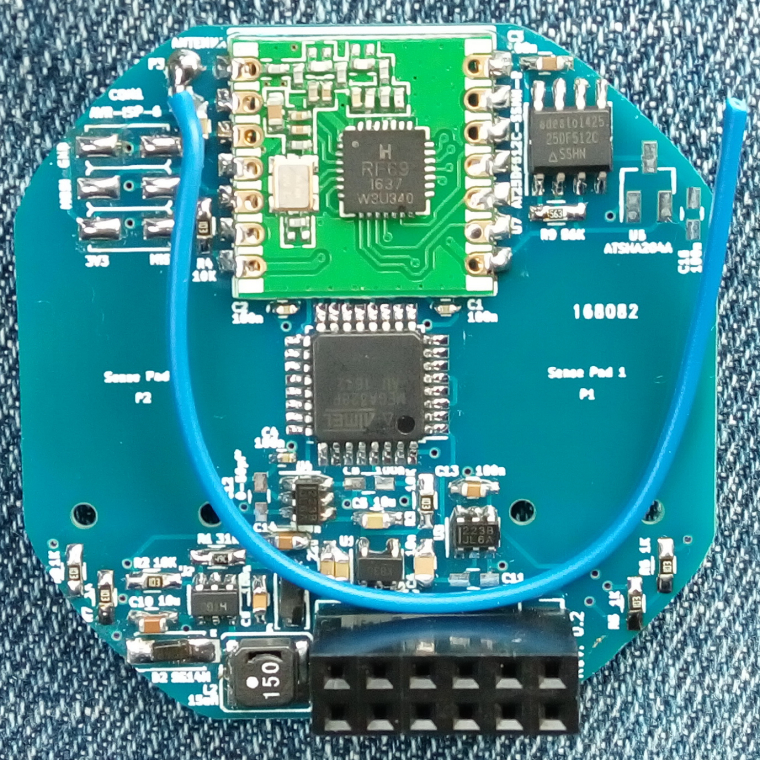
After a really long time I received the boards. I finished the assembly for one and uploaded some code to it. So far it seems to work but I need to perform some more tests. I attached some pictures of the finished product.
 .
.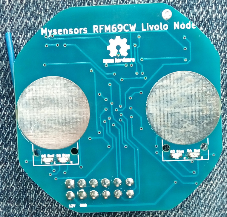
The silkscreen text is a little bit blurry and it was a little bit too small for the fab to print it so in some places is not right...anyways this is not important but the functionality is.
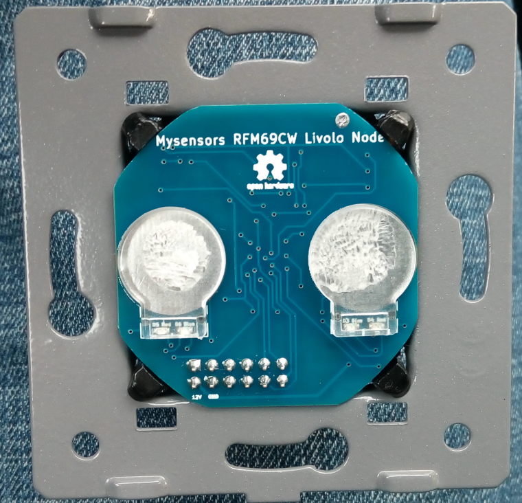
One note: the board round edges may be a little bit off the limits but that can be corrected by using some abrasive paper to remove the excess material(which I did in the above pictures and then the board fitted perfectly). -
After a really long time I received the boards. I finished the assembly for one and uploaded some code to it. So far it seems to work but I need to perform some more tests. I attached some pictures of the finished product.
. The silkscreen text is a little bit blurry and it was a little bit too small for the fab to print it so in some places is not right...anyways this is not important but the functionality is.
One note: the board round edges may be a little bit off the limits but that can be corrected by using some abrasive paper to remove the excess material(which I did in the above pictures and then the board fitted perfectly). -
I updated the project page on openhardware.io. Added instructions too. I hope that I didn't forget anything.
These are the modifications required for the power/relays board in order to work with this project:
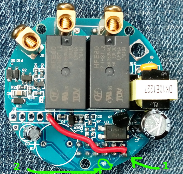
A capacitor is also needed in parallel with the light bulb otherwise the project board won't work as it doesn't get enough power from the standby circuit. I used a 470nF X2 type rated at 310Vac. I recommend using a light bulb of 10W or more(in my tests I used a 15W one.) I tested the setup with a 5W LED bulb but I got some instability from the livolo power supply board(it started to oscillate) - in this case maybe a bigger capacitor across the bulb might help(1uF one maybe). You don't need 2 capacitors in case of the 2 ways switch for each light bulb - one is sufficient across one of the bulbs.
Oh and please don't touch directly with your finger the sensor plates - use the plastics from the original board. I'm not responsible if you get an electric shock.
You can find more details in the project page on openhardware.io
Big thanks again to @jirm, @DJONvl and @Tigroenot and the rest of the community of course which contributed with the knowledge to make all this possible.
-
Hello,
i don't find anymore the VL-C700X-1 on aliexpress.
Can you tel me which is equal ?
Is it https://fr.aliexpress.com/store/product/Free-Shipping-Livolo-Luxury-White-Crystal-Glass-Switch-Panel-EU-Standard-VL-C701-11-110-250V/500715_512886492.html?spm=2114.12010612.0.0.deb0F4 ?Thx
-
Hello,
i don't find anymore the VL-C700X-1 on aliexpress.
Can you tel me which is equal ?
Is it https://fr.aliexpress.com/store/product/Free-Shipping-Livolo-Luxury-White-Crystal-Glass-Switch-Panel-EU-Standard-VL-C701-11-110-250V/500715_512886492.html?spm=2114.12010612.0.0.deb0F4 ?Thx
This one is: https://m.aliexpress.com/item/512770913.html
Please note that the board that I made is for the 2 channels model(VL-C702 series). Now I hope that they didn't changed the inside pcb hw revision meanwhile. The serial number that you mentioned and which I wrote about on openhardware project page is actually their pcb revision from inside the switch. I don't know for sure if that reflects the switch model which they advertise on AliExpress. But the link that I gave you is for the same switch which I bought some time ago because I took it from my orders list from my AliExpress account.
I see now that the price is bigger... it was 13$ when I bought it.
-
This one is: https://m.aliexpress.com/item/512770913.html
Please note that the board that I made is for the 2 channels model(VL-C702 series). Now I hope that they didn't changed the inside pcb hw revision meanwhile. The serial number that you mentioned and which I wrote about on openhardware project page is actually their pcb revision from inside the switch. I don't know for sure if that reflects the switch model which they advertise on AliExpress. But the link that I gave you is for the same switch which I bought some time ago because I took it from my orders list from my AliExpress account.
I see now that the price is bigger... it was 13$ when I bought it.
@mtiutiu Thanks you for your anwser ;)
Did you test a two way switch (va et viens) ?
I think we can do this with 1 gang 2 way :
https://fr.aliexpress.com/item/Black-Crystal-Glass-Switch-Livolo-EU-Standard-VL-C701SR-12-1-Gang-2-Way-Remote-Control/32786281129.html -
@mtiutiu Thanks you for your anwser ;)
Did you test a two way switch (va et viens) ?
I think we can do this with 1 gang 2 way :
https://fr.aliexpress.com/item/Black-Crystal-Glass-Switch-Livolo-EU-Standard-VL-C701SR-12-1-Gang-2-Way-Remote-Control/32786281129.htmlNo, I didn't tested a 2 way switch so I don't know how it behaves in that case. I don't have and I don't use switches with that setup.
-
This one is: https://m.aliexpress.com/item/512770913.html
Please note that the board that I made is for the 2 channels model(VL-C702 series). Now I hope that they didn't changed the inside pcb hw revision meanwhile. The serial number that you mentioned and which I wrote about on openhardware project page is actually their pcb revision from inside the switch. I don't know for sure if that reflects the switch model which they advertise on AliExpress. But the link that I gave you is for the same switch which I bought some time ago because I took it from my orders list from my AliExpress account.
I see now that the price is bigger... it was 13$ when I bought it.
Hi all
Can I suggest some improvements for that project?
For sure I agree with @tonnerre33 about make a version board for only one gang switch.
I buy regularly (once a month or so) some parts from livolo and from last 4 or 6 months I see that the switch plate boards (for the EU version) are the same on hardware specs at least from 6 or 9 month ago.
But we can expect that in near future (maybe few months) Livolo manufacturer make some changes and updates on his designs, because they regulary are doing that in past. So we need keep prepared for that and for make the propper updates to this project to mantain it working with the next version Livolo switchs.- -One gang switch I think is most common switch people have installed or at least I think is needed too with this two gang project version.
2.- Maybe will be better use (or make another plate board version) for the RFM69HW (high power), because the pinount on HW not match with RFM69CW you use, and HW type have same working specs but with the plus that HW type have high power possibilities and is most easy to find and both have similar price.
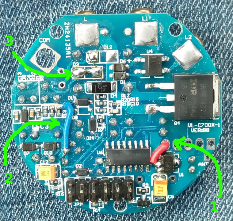
3.- How can be little better documented all the changes (wiring) we need do on the power relay plate board?
At least for me is hard to do correct wiring only seeing the photo and is easy to do some mistake trying to solder the wiring in the correct pins and places.
So I suggest trying to do some more work on that and maybe include some scheme and plan and take all best pic from each wiring bridge is needed to do that we can see without doubts the correct place to solder it.PD: @tonnerre33 I think one or two way switch function not be affected with this project plate board, because that function only differ on the pic (MCU) Livolo switch firmware and litles changes on power relay plate board to wire the additional pic pin output two way function to the COM connector.
Nothing of that function should be affected by anything that this plate modifies on the Livolo switch.My best wishes !
-
Hi all
Can I suggest some improvements for that project?
For sure I agree with @tonnerre33 about make a version board for only one gang switch.
I buy regularly (once a month or so) some parts from livolo and from last 4 or 6 months I see that the switch plate boards (for the EU version) are the same on hardware specs at least from 6 or 9 month ago.
But we can expect that in near future (maybe few months) Livolo manufacturer make some changes and updates on his designs, because they regulary are doing that in past. So we need keep prepared for that and for make the propper updates to this project to mantain it working with the next version Livolo switchs.- -One gang switch I think is most common switch people have installed or at least I think is needed too with this two gang project version.
2.- Maybe will be better use (or make another plate board version) for the RFM69HW (high power), because the pinount on HW not match with RFM69CW you use, and HW type have same working specs but with the plus that HW type have high power possibilities and is most easy to find and both have similar price.
3.- How can be little better documented all the changes (wiring) we need do on the power relay plate board?
At least for me is hard to do correct wiring only seeing the photo and is easy to do some mistake trying to solder the wiring in the correct pins and places.
So I suggest trying to do some more work on that and maybe include some scheme and plan and take all best pic from each wiring bridge is needed to do that we can see without doubts the correct place to solder it.PD: @tonnerre33 I think one or two way switch function not be affected with this project plate board, because that function only differ on the pic (MCU) Livolo switch firmware and litles changes on power relay plate board to wire the additional pic pin output two way function to the COM connector.
Nothing of that function should be affected by anything that this plate modifies on the Livolo switch.My best wishes !
@jirm said in 💬 Livolo EU switch Mysensors integration:
Nothing of that function should be affected by anything that this plate modifies on the Livolo switch.
I hope because i have many 2 way and the same for my futur home ;)
And what about NRF24L version ?
Many people are using RFM69 but 2.70$ RFM vs 1$ NRF ... Ok for command the sensitives nodes like roller shutters but why for the light ? -
No, I didn't tested a 2 way switch so I don't know how it behaves in that case. I don't have and I don't use switches with that setup.
@mtiutiu
Of course all we are here to help you make all the proper test needed with all Livolo parts that we speak. One or two gang with/and one or two way, other plate hardware revisions, etc...That all we need for do that is the avaibilitty to get your plate boards designs working on our houses.
Personally I'm so busy (and so lazy) to make all this project working from scratch trying to find plate board manufacturer, solder all (wooow smd) parts, etc... etc... and need if possible some at least "semi-mounted" plate boards printed and with the smd parts soldered.
-
@jirm said in 💬 Livolo EU switch Mysensors integration:
Nothing of that function should be affected by anything that this plate modifies on the Livolo switch.
I hope because i have many 2 way and the same for my futur home ;)
And what about NRF24L version ?
Many people are using RFM69 but 2.70$ RFM vs 1$ NRF ... Ok for command the sensitives nodes like roller shutters but why for the light ?Personally I think that much better specs from RFM vs NRF and the working radio band (433, 868 Mhz vs 2,4 Ghz) are most than enough reasons to spend that 2 $ more on RFM.
But...more always is better. So we can dream with another plate board version for NRF in the future...who knows
-
Hi all,
So after some time of testing I give you the final revision of this board which is 0.5. The latest files are available on the openhardware.io page but always the most recent are on my github repo of course(I'll try to keep both in sync anyways). By using good tantalum caps where required I got a good stability for the node. It will be kept for testing for one month still starting from this week(testing already started). So far I'm very satisfied with the results.
As a final note for all of you there: when designing hardware always use good components - especially good filtering capacitors because most of the issues and instability happens because of that.
I will try to design the pcb for the one channel variant of the switch too when I'll get my hands on it so stay tuned. I see that some people asked why RFM69 instead of NRF24L01: this is because the RFM69 module is superior in terms of performance/stability/range compared to the latter(trust me it worth the money difference as I tested both along time). And because it works in the sub-GHz band it's also less prone to interference compared to the 2.4GHz band which is used by all Wi-Fi equipment.
-
Wow, great. I guess there is no way to be able to buy these boards pre soldered w. components?
-
Hello, for information, the version has changed :( Here is the new board : https://fr.aliexpress.com/item/Free-Shipping-EU-Standard-Livolo-AC-110-250V-The-Base-Of-Wall-Light-Touch-Screen-Switch/1898648882.html
But there is good news, 3V and 12V are directly accessible ;) -
Hello, for information, the version has changed :( Here is the new board : https://fr.aliexpress.com/item/Free-Shipping-EU-Standard-Livolo-AC-110-250V-The-Base-Of-Wall-Light-Touch-Screen-Switch/1898648882.html
But there is good news, 3V and 12V are directly accessible ;)@tonnerre33 said in 💬 Livolo EU switch Mysensors integration:
Hello, for information, the version has changed :( Here is the new board : https://fr.aliexpress.com/item/Free-Shipping-EU-Standard-Livolo-AC-110-250V-The-Base-Of-Wall-Light-Touch-Screen-Switch/1898648882.html
But there is good news, 3V and 12V are directly accessible ;)Might be bad news in the (very) short term, but it will soon be much better as it means after modification to adapt to the new version @mtiutiu board should not require any hardware modification on the main power/relay PCB as 12V is now available.
-
Well..I was expecting this to happen at some point in time. This is the nasty thing that may happen when you rely on some external board(s) to do your work. It is a good thing that the 12V line is now exposed..but the pcb needs to be recreated.
And who knows in the future when it might change again. So in the end the best solution would be to have all the boards made(including the power/relays one) so that no one needs to rely on the Livolo company. But for the moment I don't have enough knowledge/time - at least not too much regarding power electronics and creating live wire only power supplies(including testing/safety/etc). -
Well..I was expecting this to happen at some point in time. This is the nasty thing that may happen when you rely on some external board(s) to do your work. It is a good thing that the 12V line is now exposed..but the pcb needs to be recreated.
And who knows in the future when it might change again. So in the end the best solution would be to have all the boards made(including the power/relays one) so that no one needs to rely on the Livolo company. But for the moment I don't have enough knowledge/time - at least not too much regarding power electronics and creating live wire only power supplies(including testing/safety/etc).
Hello! It looks like you're interested in this conversation, but you don't have an account yet.
Getting fed up of having to scroll through the same posts each visit? When you register for an account, you'll always come back to exactly where you were before, and choose to be notified of new replies (either via email, or push notification). You'll also be able to save bookmarks and upvote posts to show your appreciation to other community members.
With your input, this post could be even better 💗
Register Login