Can't ping Ethernet Gateway ENC28J60 + Arduino Nano Clone
-
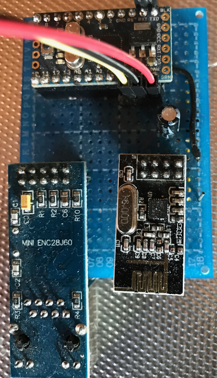
Hello I upload ENC28J60 Ethernet sample file from MySensors and it worked with MySensors Lib 2.1.1. And I used the Arduino Pro Mini, nRF24L01 Radio and ENC28J60 Ethernet. Do you use Arduino Pro Mini, you must disable debugging.
//Mattias
-
You need to 'change the IP addresses
/**
 * The MySensors Arduino library handles the wireless radio link and protocol
 * between your home built sensors/actuators and HA controller of choice.
 * The sensors forms a self healing radio network with optional repeaters. Each
 * repeater and gateway builds a routing tables in EEPROM which keeps track of the
 * network topology allowing messages to be routed to nodes.
 *
 * Created by Henrik Ekblad <henrik.ekblad@mysensors.org>
 * Copyright (C) 2013-2015 Sensnology AB
 * Full contributor list: https://github.com/mysensors/Arduino/graphs/contributors
 *
 * Documentation: http://www.mysensors.org
 * Support Forum: http://forum.mysensors.org
 *
 * This program is free software; you can redistribute it and/or
 * modify it under the terms of the GNU General Public License
 * version 2 as published by the Free Software Foundation.
 *
 *******************************
 *
 * REVISION HISTORY
 * Version 1.0 - Henrik EKblad
 * Contribution by a-lurker and Anticimex,
 * Contribution by Norbert Truchsess <norbert.truchsess@t-online.de>
 * Contribution by Tomas Hozza <thozza@gmail.com>
 *
 *
 * DESCRIPTION
 * The EthernetGateway sends data received from sensors to the ethernet link.
 * The gateway also accepts input on ethernet interface, which is then sent out to the radio network.
 *
 * The GW code is designed for Arduino 328p / 16MHz.  ATmega168 does not have enough memory to run this program.
 *
 * LED purposes:
 * - To use the feature, uncomment WITH_LEDS_BLINKING in MyConfig.h
 * - RX (green) - blink fast on radio message recieved. In inclusion mode will blink fast only on presentation recieved
 * - TX (yellow) - blink fast on radio message transmitted. In inclusion mode will blink slowly
 * - ERR (red) - fast blink on error during transmission error or recieve crc error
 *
 * See http://www.mysensors.org/build/ethernet_gateway for wiring instructions.
 *
 */

// Enable debug prints to serial monitor
#define MY_DEBUG

// Enable and select radio type attached
#define MY_RADIO_NRF24
//#define MY_RADIO_RFM69

// When ENC28J60 is connected we have to move CE/CSN pins for NRF radio
#define MY_RF24_CE_PIN 5
#define MY_RF24_CS_PIN 6

// Enable gateway ethernet module type
#define MY_GATEWAY_ENC28J60

// Gateway IP address
#define MY_IP_ADDRESS 192,168,0,178

// The port to keep open on node server mode / or port to contact in client mode
#define MY_PORT 5003

// Controller ip address. Enables client mode (default is "server" mode).
// Also enable this if MY_USE_UDP is used and you want sensor data sent somewhere.
#define MY_CONTROLLER_IP_ADDRESS 192, 168, 0, 201

// The MAC address can be anything you want but should be unique on your network.
// Newer boards have a MAC address printed on the underside of the PCB, which you can (optionally) use.
// Note that most of the Ardunio examples use  "DEAD BEEF FEED" for the MAC address.
#define MY_MAC_ADDRESS 0xDE, 0xAD, 0xBE, 0xEF, 0xFE, 0xFE

// Flash leds on rx/tx/err
//#define MY_LEDS_BLINKING_FEATURE
// Set blinking period
#define MY_DEFAULT_LED_BLINK_PERIOD 300

// Enable inclusion mode
#define MY_INCLUSION_MODE_FEATURE
// Enable Inclusion mode button on gateway
#define MY_INCLUSION_BUTTON_FEATURE
// Set inclusion mode duration (in seconds)
#define MY_INCLUSION_MODE_DURATION 60
// Digital pin used for inclusion mode button
#define MY_INCLUSION_MODE_BUTTON_PIN  3

#define MY_DEFAULT_ERR_LED_PIN 7  // Error led pin
#define MY_DEFAULT_RX_LED_PIN  8  // Receive led pin
#define MY_DEFAULT_TX_LED_PIN  9  // the PCB, on board LED

#include <SPI.h>
#include <UIPEthernet.h>
#include <MySensors.h>


void setup()
{
}

void loop() {
}
//Mattias
-
@MLs
I think you use enc28 ethernet module not shieldI have same code but no ping if nrf not commented
-
Ok, you have linked NRF24 radio right?
https://www.mysensors.org/build/ethernet_gateway#enc28j60-ethernet-module
Also verified that the shield is properly attached?
//Mattias -
@MLs
Nano with shield and no nrf24 ping only with commented nrf24
Then uncomment nrf24 GW has no connection over ethernet
No ping no telnet -
There I can say is that the circuit ENC28J60 works with MySensors lib 2.1.1
Try to connect your components to breadboard.
Hello! It looks like you're interested in this conversation, but you don't have an account yet.
Getting fed up of having to scroll through the same posts each visit? When you register for an account, you'll always come back to exactly where you were before, and choose to be notified of new replies (either via email, or push notification). You'll also be able to save bookmarks and upvote posts to show your appreciation to other community members.
With your input, this post could be even better 💗
Register Login