💬 Livolo 3 buttons US/AU switch adapter
-
And I have synchronized signals on the 3 pin too (TX, RX and RB4 pin). The TX and RX pins are obviously those used for communication as the signal on those pin always follow a level change on RB4 pin.
-
@tonnerre33 but they are connected to the PIC MCU on the main PCB, that would make no sense if those pins were used with the radio ?
@Nca78 said in 💬 Livolo 3 buttons US/AU switch adapter:
It's true. Can you take a picture of you pic mcu main board ? It's for compare with my EU board ;) -
@Nca78 said in 💬 Livolo 3 buttons US/AU switch adapter:
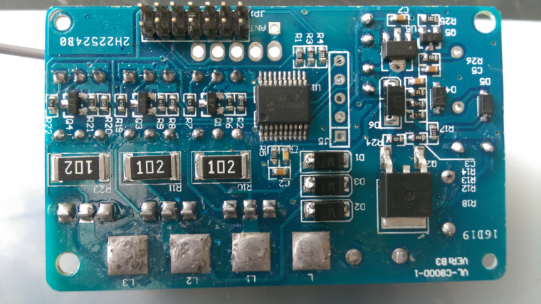
It's true. Can you take a picture of you pic mcu main board ? It's for compare with my EU board ;)@tonnerre33 sure, here you are.
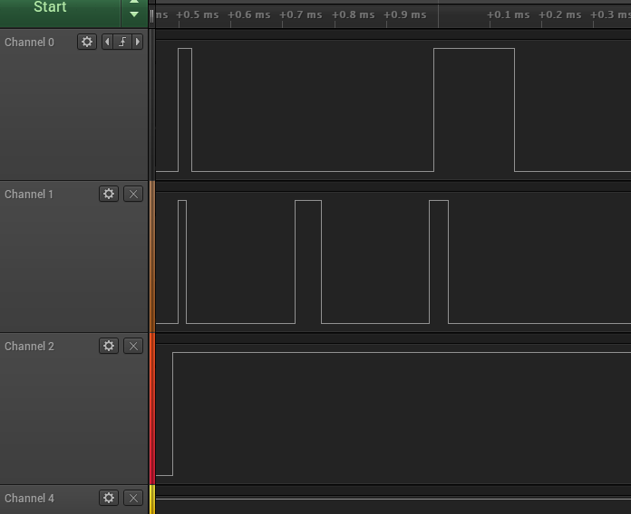
Pins I'm checking with the logic analyser are connected to the PIC using the R1, R3, R4 200 Ohms resistors (top right of the PIC) they are the only ones I see connected to the PIC.
-
So maybe I will need help/advice from someone who has a bit of knowledge about this kind of data exchange between 2 processors, to see if it rings a bell for them... @scalz maybe (sorry to bother you :))
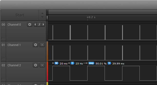
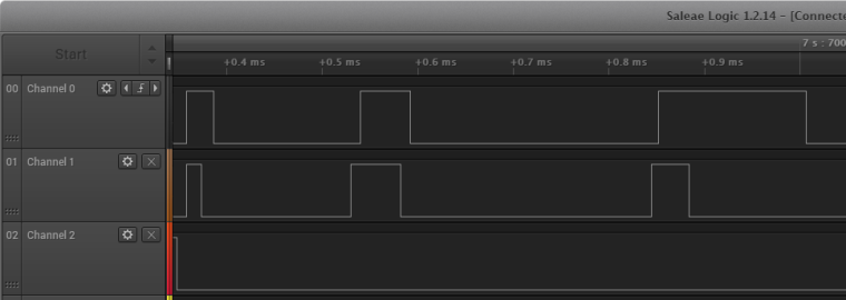
Channel 2 is connected to RA4 (touch PCB PIC) and RB4 (main PCB PIC). It's obviously a clock signal, at 25Hz, 50% duty cycle. Each edge (raising and falling) generates pulses on the 2 other pins.
Channel 0 is connected to pin RB7/TX/CK.
Channel 1 is connected to pin RB5/AN11/RX/DT
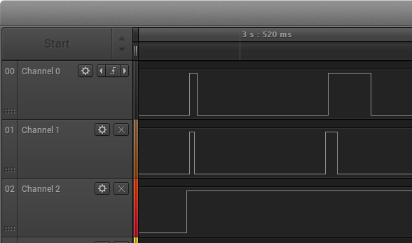
What I see is this base signal, with some pulse that are always repeated every 20ms:- edge on C2 triggers pulses on C0 and C1 (both at the same time) with a 12us delay. I call them "start" pulses later.
- C1 pulse lasts 16us, it's falling edge triggers a falling edge on C0 with 10us delay
- after 260us there is another pulse on C1, triggering another pulse on C0 with a 10us delay. I call them "end" pulses later.
- C1 pulse last 40us, C0 pulse 152us
- duration between start and end pulses is always the same (468us)
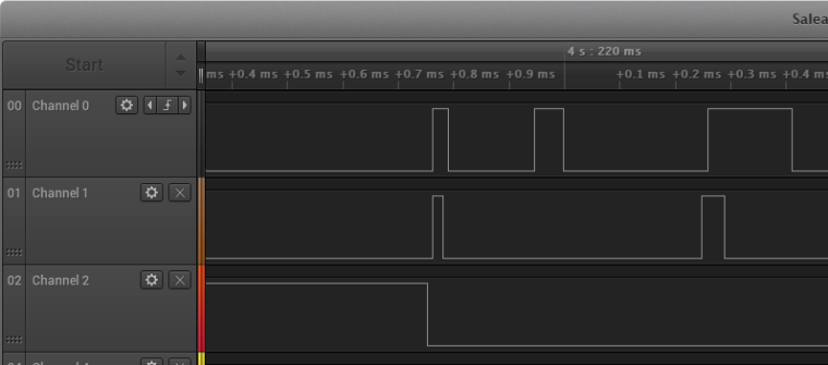
Adding to that base signal, I have some "extra" pulses that appear between the start/end pulses, in 3 different
- pulse on C1 208us after start pulse ,
- pulse on C1 208us after start pulse, followed 10us later by another pulse on C0 with 10us delay
- pulso on C1 156us after start pulse, no pulse on C1. I've seen this case only once. Signal repeated 7 times then
I have not seen the case where a pulse on C1 happens after a pulse on C0, but maybe it happened and I just missed it as it's pretty hard to search in the logic software for this case ...
As the pulses always have the same duration, my stupid guess is middle pulse between start end end pulse = 1, no middle pulse = 0. Plausible ? Not ? Anything specific I should check ?
Any suggestion is welcome :)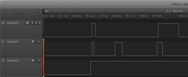
-
@Nca78 - only 500 pieces :) That's OK though, they're cheap, I already ordered the 0603 ones, just hoping my soldering skills are going to be enough for that size. Let me know as soon as you decide on the res/cap packages. I have only 0805, but can order something else if needed.
Thanks for keeping me in the loop and hope you will be able to crack that protocol!@achurak1 I'll give up on the dimmer at the moment as I need to spend more time on my NModule projects.
I kept TX and RX pins connected as they can be used as normal digital pins, and I connected D3 to what I see is the clock pin so it should be possible to use dimmers in the future.
I have 3 extra LEDs in place but #4 is challenging to route so maybe I will not put it.
I'm thinking about a version with ws2812b too as it would be much more convenient than those extra LEDs, both to route and to use. -
@Nca78
sorry i miss time to take a look at your project actually. will do it later if i can, as it's always easier with the hardware for debugging this. I don't have this livolo version, only a one button version, but i'm still wondering how much it costs to use a Livolo+custom made mysensors board VS redesigning completely one -
@Nca78
sorry i miss time to take a look at your project actually. will do it later if i can, as it's always easier with the hardware for debugging this. I don't have this livolo version, only a one button version, but i'm still wondering how much it costs to use a Livolo+custom made mysensors board VS redesigning completely one@scalz said in 💬 Livolo 3 buttons US/AU switch adapter:
@Nca78
sorry i miss time to take a look at your project actually. will do it later if i can, as it's always easier with the hardware for debugging this. I don't have this livolo version, only a one button version, but i'm still wondering how much it costs to use a Livolo+custom made mysensors board VS redesigning completely oneThank you but I just wanted to know if you had seen something like that before ? Any lead to protocole/example/anything that could make me on the right track (or not, as long as I learn something I won't complain) is welcome :)
For redesigning one, well this kind of power supply using live wire only is beyond my knowledge at the moment, and I can't pull neutral wire to have it in my switches. For around 20€ delivered for a full Livolo switch it costs 25-30€ to have a MySensors version, I'm not sure there's much money to save
-
@scalz said in 💬 Livolo 3 buttons US/AU switch adapter:
@Nca78
sorry i miss time to take a look at your project actually. will do it later if i can, as it's always easier with the hardware for debugging this. I don't have this livolo version, only a one button version, but i'm still wondering how much it costs to use a Livolo+custom made mysensors board VS redesigning completely oneThank you but I just wanted to know if you had seen something like that before ? Any lead to protocole/example/anything that could make me on the right track (or not, as long as I learn something I won't complain) is welcome :)
For redesigning one, well this kind of power supply using live wire only is beyond my knowledge at the moment, and I can't pull neutral wire to have it in my switches. For around 20€ delivered for a full Livolo switch it costs 25-30€ to have a MySensors version, I'm not sure there's much money to save
-
@Nca78 - Hi! Haven't heard from your for quite some time :) Any progress with this? Were you able to resolve the poor sensitivity issues?
@achurak1 said in 💬 Livolo 3 buttons US/AU switch adapter:
@Nca78 - Hi! Haven't heard from your for quite some time :) Any progress with this? Were you able to resolve the poor sensitivity issues?
Hello !
Sorry I'm testing NModule and all shields at the moment.
Then I'll work on this again and make some PCBs. -
@Nca78 - I'm not sure if you've seen this or not, but someone seems to have managed to crack the dimmer protocol in this thread: https://forum.mysensors.org/topic/2775/livolo-glass-panel-touch-light-wall-switch-arduino-433mhz
-
@Nca78, yes very interesting in Livolo hacking in order to get feedback status that is not available by default. Any progress on your end?
@DenisPac said in 💬 Livolo 3 buttons US/AU switch adapter:
Any progress on your end?
Not yet, I'm still testing other boards, then I will fix a batch of PCBs including this one and order.
Not sure if I keep the many leds or if I try to put a ws2812b though... -
Hello, I have finally finished a new version of this board, I will double check tomorrow and order PCB before end of week.
Changes :
- radio moved between 2 buttons, it should fix the touch sensing problem on the third button
- touch pads improved using restrict layers to keep constant distance between touch electrode and ground planes, it should give much more margin to set sensitivity of each pad with the Cs capacitors of the TTP223
- added a ws2812B for middle button instead of the "extra leds". I'm not 100% sure that it will work...
- rearranged all components on the PCB, so they are properly aligned instead of the mess it was before
-
I assembled a new board and quickly tested on a switch. There's a software bug that prevents the relays to switch and I'm out of SMD leds, so it was a bit difficult to test efficiently, but I could check on domoticz if buttons were activated, good news is it works for the 3 buttons so I can keep this design.
I put the SK6812 on central button and it can run but unfortunately it's too thick so light is not visible when glass cover is on :( Meaning I'll have to make a new version with SK6812mini which is thinner (less than 1mm against 1.6), or use a RGB side led which is not a convenient solution as atmega is missing pins and PWM capabilities. So I guess I'll try the mini version first to try to keep the component count as low as possible.Tomorrow I'll steak some leds from another project and make more tests for touch to make sure the problem on third button is solved.
(meanwhile the old version PCB is great for one button switches, I installed one 2 months ago and it's been running perfectly, 100% instant response by touch or via controller).
-
I'm very interested in this project. I suppose it isn't too hard for me to swap the microcontrollers to something like an ESP or Photon? I just want WIFI capability :) I never bought anything on openhardware / mysensors before, does this come with all parts soldered (plug and play), or will I have to assemble?
Sorry for all the questions!! Thanks
@htko89 hello !
No one openhardware you only have the PCBs, it's possible to link to an eBay shop to sell fully assembled PCBs buy I'm not planning to do it.
You can't replace with a wifi board/chip as you can't draw enough power from thr "main" board.
Your choices are:- use MySensors and control using WiFi through the smart home controller
- replace main board with a transformer that will provide enough power. But you will need live+neutral
- buy a sonoff wall switch, it's cheap but you will also need live and neutral wires
And don't buy on openhardware now it's not a finished project and I will changed it some more...
-
Hey, I was just wondering if you finished this project?
-
Hey, I was just wondering if you finished this project?
@marcusakamg7 said in 💬 Livolo 3 buttons US/AU switch adapter:
Hey, I was just wondering if you finished this project?
Hello, I made two, one with one button, one with three. The one with three buttons stopped running after a power outage because of radio failure, I'm not sure what happened but I had some problems with radios on other boards so maybe a batch with faulty components. But it could be related to the board using too much current and heating up too much, or overvoltage when power came back. Switch with one button is still running perfectly but it's used much less.
I have bought new radios and will provably assemble new boards soon, but it's not my priority project at the moment.
-
is it possible to get the file for the one button switch, i would like to order the pcb and try it out.