livolo Glass Panel Touch Light Wall Switch + arduino 433Mhz


  • Hi all,
    someone has already use livolo Glass Panel Touch Light Wall Switch (or livolo like) ?
    I found a arduino library to work with it, but I'm not sure switch below is a 433Mhz compatible:

    http://www.ebay.fr/itm/1-2-Gang-Luxury-Crystal-Glass-White-Panel-Touch-Remote-LED-Home-Light-Switch-WT-/191733281508?var=&hash=item2ca431b2e4Ⓜm1mrBR79UU2TK5oqUF7AxrA


  • Admin

    Couldn't find any info about radio control in the description. But it surely looked nice.


  • Hi @hek
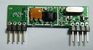
    In ebay pictures you can see 433Mhz receiver...
    screenshot-www ebay fr 2016-01-10 21-02-17.png

    is it the same no ?
    433.jpeg


  • Admin

    Might be best to ask the seller to be sure. They might have versions w/o radio.


  • yes,
    I'm going to ask 😉


  • @mickaelh51 ,

    I found this post on the arduino forum, and his seller said it is 433.92Mhz


  • Hi, check domoticz forum, there are some infos too.


  • Hi,

    Kind late, but if you still interest I just got my livolo switchs working with mysensors. The 433mhz transmiter has a short range without a antenna and trying to control the living room lights from the adjacent bedroom fails about half the time. But the real downside is that the switch doesnt transmit/report its state, so you cant really know if the lights is on or off. If you are mostly interested in remote control that's ok because you just keeping pressing the button until the light is on/off, but if you are interested in some kind of automation (like, turn the lights on at 6pm) knowing the state is important. Thats sad because the switches really looks good and the touch is good.


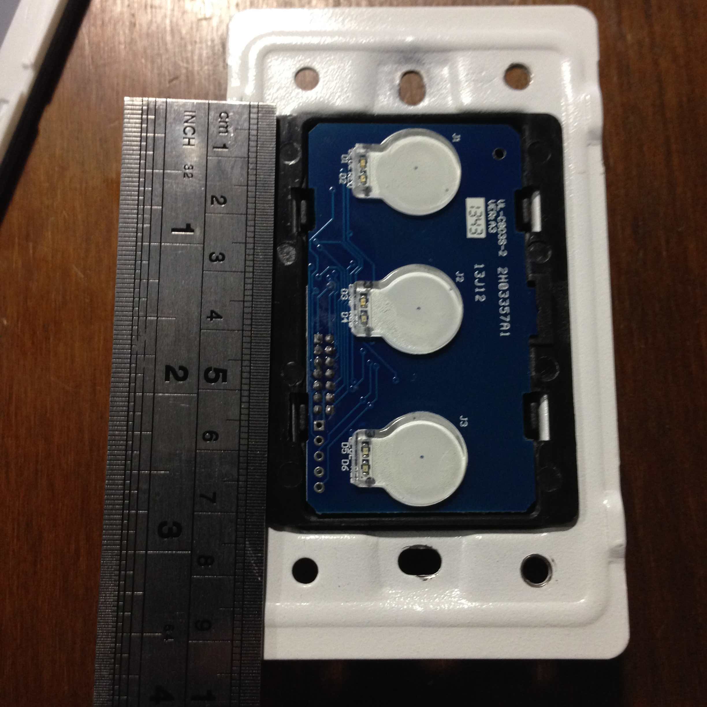
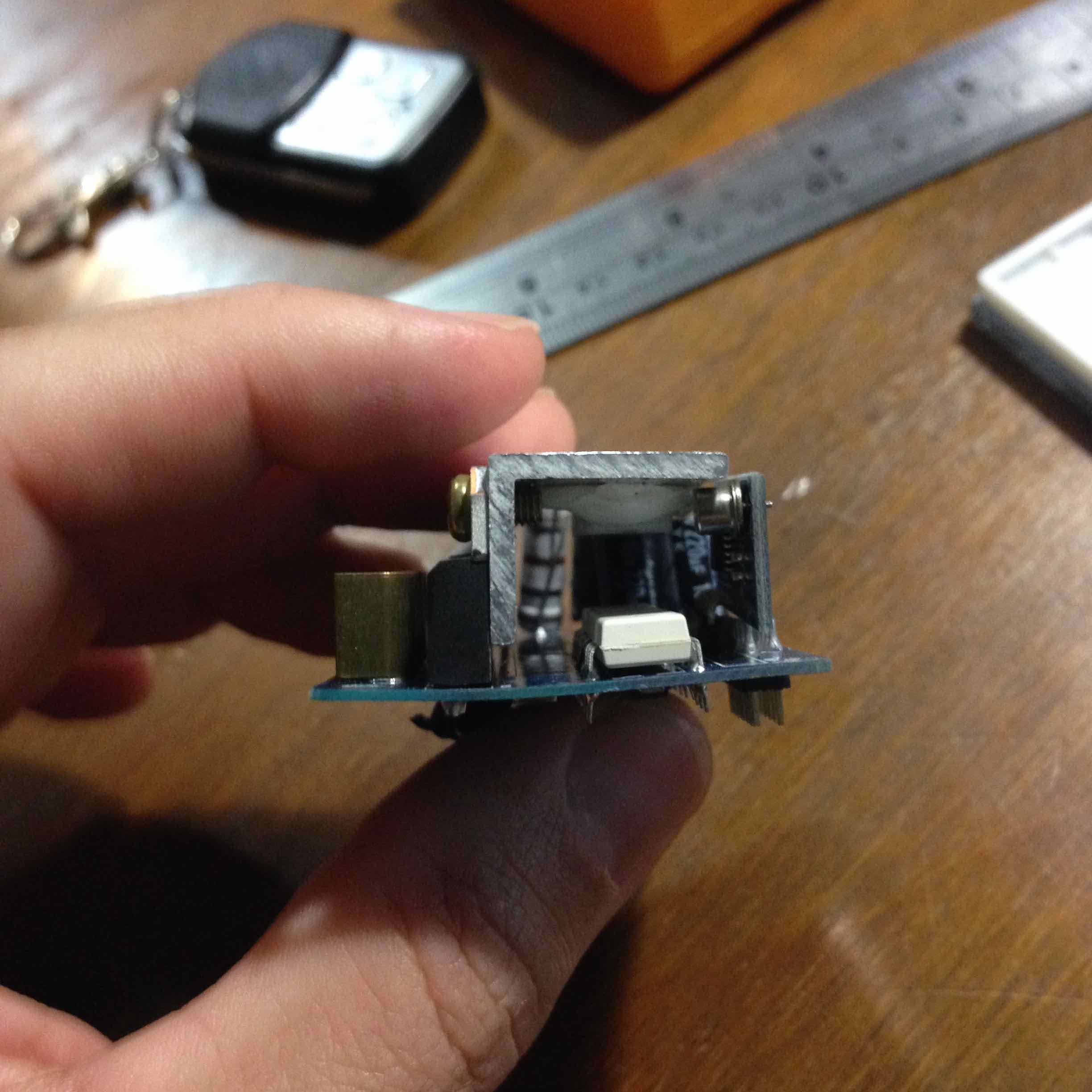
  • @chrlyra how much space is inside the switch? could there be enough room for an arduino+ nrf24 instead of the 433mhz transmitter?

    would be great if you could post some photos of the backside (because thats where the electronics are i think?)


  • @HenryWhite, sure. I had a couple of switches arriving next week and will take some photos before installing them.


  • Hardware Contributor

    Great, I am interested too! They definitly look great 😉 Although I am unsure about using "china" hardware with mains in my apartment (ensurance issues?)


  • Hardware Contributor

    I found these a while back, and was very tempted to go the route of modding these to work with mysensors with a nRF24L01 inside rather than the poor 433mhz transceiver.

    However, for a few reasons i went the route of creating my own wireless light switch that can be used with any rocker/momentary switch front. Project can be found here.

    I'm currently in the process of finding some sleek way of making a capacitive touch front plate for this module to make it look somewhat like these Livolo glass switches. It may come to purchasing these just for the face-plate and then removing the rest of the product.


  • Hi,

    Here we go (sorry for the poor lightning):
    0_1468703927962_livolo switch 1.jpg

    0_1468703941041_livolo switch 2.jpg

    0_1468703956374_livolo switch 3.jpg

    0_1468703979869_livolo switch 4.jpg


  • @Samuel235 nice! Since I barely know how to solder I ended going for the livolo. But I may ask for friends help if we find a way to mod the livolo. Btw, since you will change the internals you may look for the ones without RF as they would be even cheaper.


  • Hardware Contributor

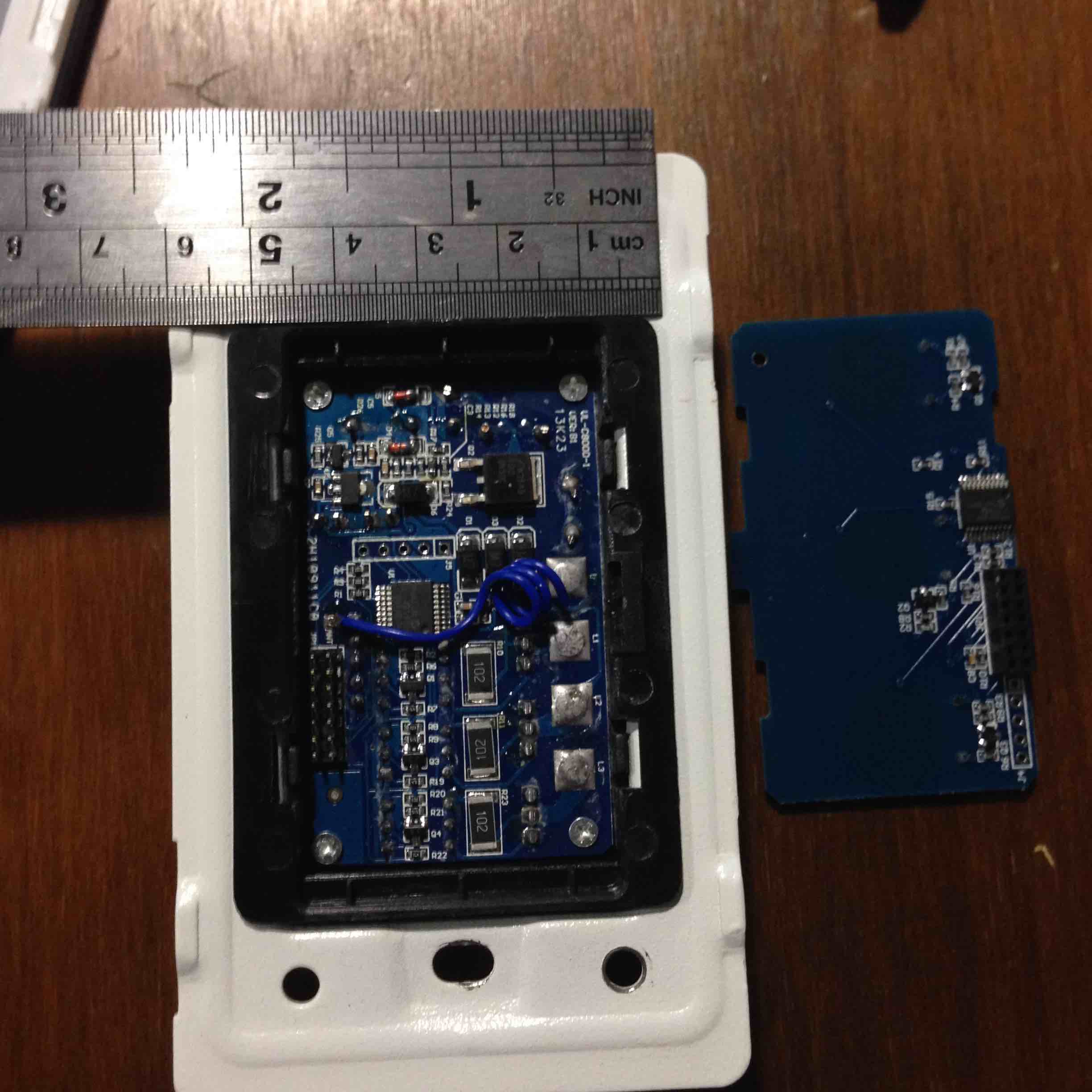
    Thank you for providing images @chrlyra, it looks poorly made at the least, only from looking at these images though. You're correct in saying i could purchase these without the internal radios if i just specifically want the face-plate. Its a shame they're so cheaply manufactured, they have some real potential, not for me now i know how dodgy these look on the internals.

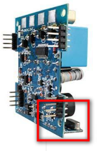
    They also look like they do all the switching through mosfets rather than relays, which is fine if controlled correctly. The mosfet on the first image looks something along the lines of a Power MOSFET in a DPAK package, N-Channel or P-Channel.

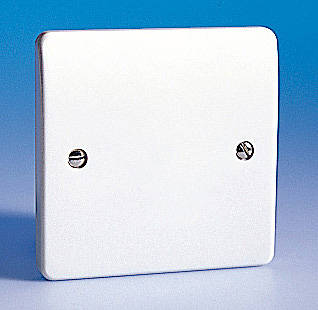
    I'm very intrigued at those touch sensors, very nifty looking items. If someone know how to find those on the internet please inform me, i'm very interested in those. The only way i'm thinking of remaking something like those would be to create a capacitive touch sensor behind a blank wall plate, one of these. They don't look very stylish though, i need to come up with some other product for my project.


  • Hardware Contributor

    I think if you want to reuse the livolo that won't be easy. I have one livolo, without radio and no dimmer. So it uses relay. I know about the mosfet version. I think mosfet is nice too.

    I have already unpacked it and checked some electricals connection because I was thinking to hack it. But I think this is too much pain for maybe not great results.

    On mine, the brain mcu is on the capacitive plate (a microchip mcu). I have not tried to access/change fw of the mcu though but I thought, well, I could do another plate and reuse relay board, easy!..but then there is the radio. Reuse the livolo one? some work, not the best perf, no state back.. Use my rfm69 radio (I prefer 868 than 433) ? I'm not sure the livolo can provide power I need etc... so it could put me on a tricky road for not great results, looking not good inside the box..

    Too bad! Because my livolo is well built and I like the glass plate. I want the glass plate!! It's cheap and you have the whole enclosure.
    So finally, I have a project in progress where I do everything from scratch, with glass plate and gesture, yep 😉 but I don't know yet when it will be finished as I have a few other things to finish.


  • 1_1468756025188_WP_20160716_22_14_16_Prok.jpg 0_1468756025187_WP_20160709_22_07_06_Prok.jpg

    0_1468756052784_WP_20160716_22_14_16_Prok.jpg

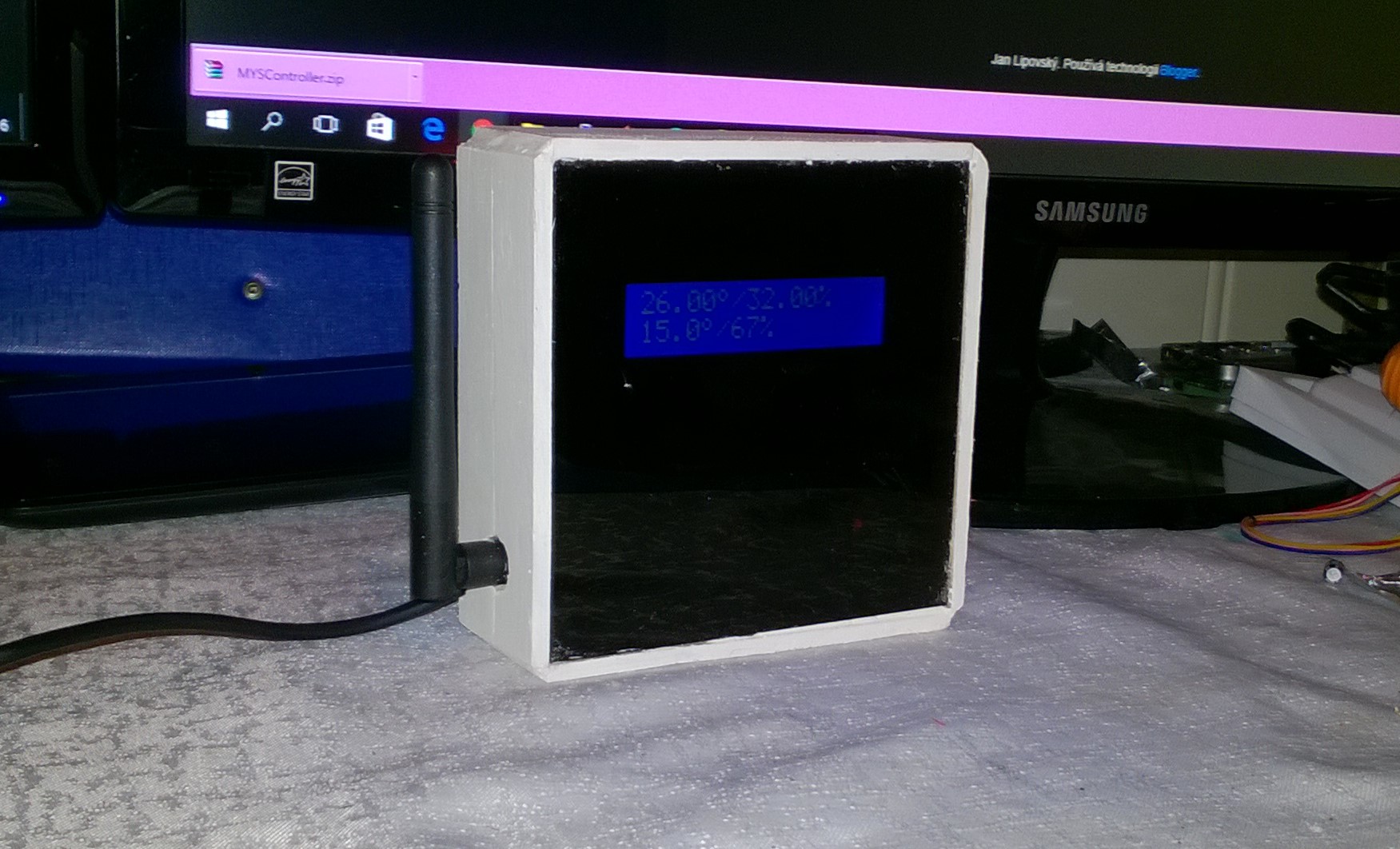
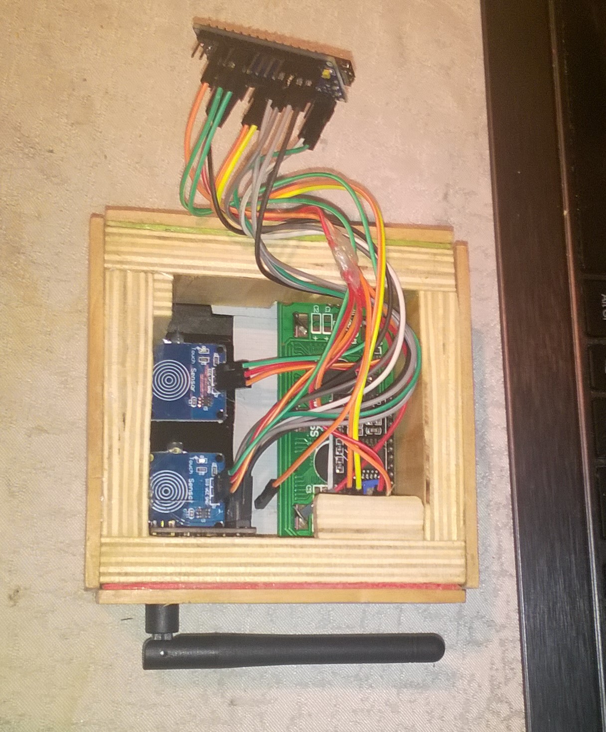
    Im just about to finish this one, i use a black (transparrent) acrylic plate with touchmodules and LCD behind the acrylic.


  • Hardware Contributor

    Hello, I just found out that Livolo is selling the glass plates (EU standard only, too bad for me 😞 ) alone on it's aliexpress shop. 3.72€ for square plate (1 or 2 switches), 6.24€ for double sized plate (up to 4 switches) and 8.77€ for triple size (up to 6 switches !).

    I have US(AU) sized switches here so I'm a bit screwed up, but I think I will try to order a double plate and put on top of one of my switches boxes which are a bit smaller.
    Check the "EU DIY Parts" category in the Livolo shop.

    http://www.aliexpress.com/item/Livolo-Luxury-White-Pearl-Crystal-Glass-80mm-80mm-EU-standard-Single-Glass-Panel-For-1-Gang/32484221458.html


  • Hardware Contributor

    @Nca78 that's what I'm planning to do 😉 you can't find cheaper for already cutted glass plate imho. I'm redesigning the box for 3d printing, and maybe sand and repeint the plate, I'm note sure yet as I don't really care about the button layout (I will use gesture).


  • Hardware Contributor

    @Nca78 - Very interesting, thank you for linking that! So any sort of capacitive touch sensor behind the button on this glass panel should be good to go. I think o.O I will have to see about ordering one to try out.

    @scalz - Fill us in with some more info and images regarding your gesture design 😉


  • Hardware Contributor

    @scalz said:

    @Nca78 that's wat I'm planning to do 😉 you can't find cheaper for already cutted glass plate imho. I'm redesigning the box for 3d printing, and maybe sand and repeint the plate, I'm note sure yet as I don't really care about the button layout (I will use gesture).

    It depends for the price, if there is a local maker here it can end up cheaper than on aliexpress.
    What sensor are you planning to use for the touch ? TTP22x for relative ease of soldering, or an hardcode 3x3mm MPR121 ?

    [edit] Just found cheaper panels here (for simple EU size, bigger sizes are more expensive), but maybe a bit less sexy
    http://www.aliexpress.com/store/product/3gang-white-small-glass-switch-panel-match-with-Bingo-Elec-frame-glass-or-aluminum-and-3gang/1157683_32394538766.html


  • Hardware Contributor

    @Nca78 yep. sure I thought about this. it depends also of the quantity, as locals are not always the cheaper, at least where I live lol. about the sensor, I use gesture (more hygienic and cool) so it's more complicated than common sensor. and no cheap eval board so I made mine and variant for those interested. but you will see, I will show sure 😉


  • Hardware Contributor

    @scalz - Very very interested, might even make a purchase 😉

    @Nca78 - Thank you for that link for a price comparison, looks tempting.


  • Hardware Contributor

    @Samuel235 said:

    @Nca78 - Thank you for that link for a price comparison, looks tempting.

    You're welcome. I ordered the three size of plates to see how I can use them in my home. I will test with TTP and MPR121 and give a feedback.

    @scalz made me look for gesture sensors and I discovered the ADPS 9960, it was too tempting not to order one, can't wait to receive and play with it !


  • Hardware Contributor

    @Nca78 said:

    @scalz made me look for gesture sensors and I discovered the ADPS 9960, it was too tempting not to order one, can't wait to receive and play with it !

    I'm also now looking up these. Times like this i wished i had a workshop to manufacture things like a switch plate myself out of plexi with a gesture sensor behind with leds lighting the frosted plate up as you signal movements to the sensor.


  • Hardware Contributor

    @Samuel235 stop looking in my mind 🙂 I have already some working proto though for the plate pcb 😉 but I'm waiting a bit for posting vids, I have others projects to show running in vid before this one. or maybe I will show everything at same time. i don't know yet 🙂 I miss a bit of time..


  • Hardware Contributor

    @scalz said:

    @Samuel235 stop looking in my mind 🙂 I have already some working proto though for the plate pcb 😉 but I'm waiting a bit for posting vids, I have others projects to show running in vid before this one. or maybe I will show everything at same time. i don't know yet 🙂 I miss a bit of time..

    Damn you! Stop stealing my aspirations! Please, just make sure you share the products with us!


  • Hardware Contributor

    @scalz said:

    On mine, the brain mcu is on the capacitive plate (a microchip mcu). I have not tried to access/change fw of the mcu though but I thought, well, I could do another plate and reuse relay board, easy!..but then there is the radio. Reuse the livolo one? some work, not the best perf, no state back.. Use my rfm69 radio (I prefer 868 than 433) ? I'm not sure the livolo can provide power I need etc... so it could put me on a tricky road for not great results, looking not good inside the box..

    Hello, I have ordered one full livolo switch, single button with no radio.
    And I think I will disagree with you on this 🙂

    I've soldered some pins on the available headers (next to the 2*7 connector) and plugged a sensor on the GND and 3V pins.
    The switch is still running fine, led on and I can switch the lights on and off. The sensor is running and sending data very reliably at the moment meaning even on the non-radio version of the switch the power is clean enough for NRF24 radio. This is true for both lights on and off.

    It might not be true when using the 4 switches version with all relays on, but this is making me very confident about the 2/3 switches version which would fill my needs.
    I'm using US sized switches also, so maybe (probably) the power supply is not the same on the EU sized switches that has a maximum of 2 relays.

    0_1477888490554_IMAG1046.jpg


  • Hardware Contributor

    @Cristian-Tone said:

    this guy did some work on this:
    LIVOLO TOUCH SWITCH HACKED – 00:20
    — Doug Schafer

    Yes I have seen it but it's a completely different concept. They reprogram the PIC on the sensor board so it will send data to a computer over serial. And last time I saw it they had to change the relays also to put 5V relays instead of 12V.
    It's much cleaner to just replace the sensor board and communicate through radio...


  • @Nca78 Indeed, I've done some more research on this too and I agree with you, it would have been nice though. 🙂


  • это моя переделка китайского Livolo arduino+nrf24, красным на фото отмечено куда ставить перемычки на плату для повышения мощности блока питания в режиме ожидания,
    3_1481003871578_IMG-20161127-WA0005.jpg 2_1481003871577_IMG-20161127-WA0003.jpg 1_1481003871577_IMG-20161127-WA0002.jpg 0_1481003871575_IMG-20161127-WA0001.jpg


  • Hardware Contributor

    Hello @DJONvl could you post in English please ? 🙂
    It looks interesting, are you hacking the touch pad signal to simulate user touch ? And the led voltage to know the current status ?


  • к сожалению не говорю по английски, вот код для ясности 😃

    #include <SPI.h>
    #include <MySensor.h>
    
    #include <Bounce2.h>
    #define sensor_PIN  6
    #define RELAY_PIN  A3  // Arduino Digital I/O pin number for relay 
    #define BUTTON_PIN  5  // Arduino Digital I/O pin number for button 
    #define CHILD_ID 1   // Id of the sensor child
    #define RELAY_ON 1
    #define RELAY_OFF 0
    
    Bounce debouncer = Bounce(); 
    int oldValue=0;
    bool state;
    bool sens;
    
    MySensor gw;
    MyMessage msg(CHILD_ID,V_LIGHT);
    
    void setup()  
    {  
      delay(2400);
      
      gw.begin(incomingMessage, AUTO, true);
    
      // Send the sketch version information to the gateway and Controller
     // gw.sendSketchInfo("Livolo", "1.0");
    
     // Setup the button
      pinMode(BUTTON_PIN,INPUT);
      pinMode(sensor_PIN,INPUT);
      // Activate internal pull-up
      digitalWrite(BUTTON_PIN,HIGH);
      
      // After setting up the button, setup debouncer
      debouncer.attach(BUTTON_PIN);
      debouncer.interval(5);
    
      // Register all sensors to gw (they will be created as child devices)
      gw.present(CHILD_ID, S_LIGHT);
      delay(1400);
      // Make sure relays are off when starting up
      digitalWrite(RELAY_PIN, RELAY_OFF);
      // Then set relay pins in output mode
      pinMode(RELAY_PIN, OUTPUT);   
          
      // Set relay to last known state (using eeprom storage) 
     // state = gw.loadState(CHILD_ID);
      //digitalWrite(RELAY_PIN, state?RELAY_ON:RELAY_OFF);
    state=false;
    }
    
    
    /*
    *  Example on how to asynchronously check for new messages from gw
    */
    void loop() 
    {
      gw.process();
      //debouncer.update();
      // Get the update value
      
     int value =digitalRead(sensor_PIN);
        if (value==1){
          state=true;
        }else{
          state=false;
        }
    
      if (value != oldValue) {
          gw.send(msg.set(state), true); // Send new state and request ack back
      }
      oldValue = value;
    } 
     
    void incomingMessage(const MyMessage &message) {
    
    
      if (message.type == V_LIGHT) {
         // Change relay state
        bool instate = message.getBool();
    
     while(instate!=state){
         digitalWrite(RELAY_PIN, RELAY_ON); 
         delay(60);
         digitalWrite(RELAY_PIN, RELAY_OFF);  
         delay(60);     
        int value =digitalRead(sensor_PIN);
        if (value==1){
          state=true;
        }else{
          state=false;
        }
     }    
        
    
       } 
    }


  • Sorry if this already has been covered in the thread but I can't find the info. When looking at ebay it looks like the connectors are L = in, L1, = out (for one way). But how are the radio/touch etc powered? is there also a battery inside or can you power the switch without neutral wire?


  • Hardware Contributor

    @Cliff-Karlsson it takes the voltage from live wire only. It generates a light voltage drop and from there gets enough power to run the circuit.
    The downside is it constantly have to leak a bit of current through the live wire, so if you have a small light connected to it it might flicker. Livolo sells some small unit you can connect to your load and that will let the current pass and save your lights from premature death because of flickering. But it all depends on the light bulbs and also on the quality/efficiency of the switches.


  • There really is an opportunity to draw enough power from livolo internal circuits for atmega328 and a radio. With the great help of @DJONvl I managed to power up an arduino with nrf24 radio directly from the switch.
    But...
    I have a two button switch, and i tried to adopt the above scetch for my purpose (and the development version of the library) but got stuck... Can anyone please have a glance at my scetch and push me towards the right way? 🙂

    /**
     * The MySensors Arduino library handles the wireless radio link and protocol
     * between your home built sensors/actuators and HA controller of choice.
     * The sensors forms a self healing radio network with optional repeaters. Each
     * repeater and gateway builds a routing tables in EEPROM which keeps track of the
     * network topology allowing messages to be routed to nodes.
     *
     * Created by Henrik Ekblad <henrik.ekblad@mysensors.org>
     * Copyright (C) 2013-2015 Sensnology AB
     * Full contributor list: https://github.com/mysensors/Arduino/graphs/contributors
     *
     * Documentation: http://www.mysensors.org
     * Support Forum: http://forum.mysensors.org
     *
     * This program is free software; you can redistribute it and/or
     * modify it under the terms of the GNU General Public License
     * version 2 as published by the Free Software Foundation.
     *
     *******************************
    */
    
    
    #define MY_RADIO_NRF24
    #define MY_REPEATER_FEATURE
    #include <MySensors.h>
    
    #define sensor1_PIN 5
    #define sensor2_PIN 6
    #define RELAY1_PIN 3  // Arduino Digital I/O pin number for relay 
    #define RELAY2_PIN 4 
    #define CHILD_ID_LIGHT1 1   // Id of the sensor child
    #define CHILD_ID_LIGHT2 2
    #define RELAY_ON 1
    #define RELAY_OFF 0
     
    int oldValue1=0;
    bool state1;
    bool sens1;
    int oldValue2=0;
    bool state2;
    bool sens2;
    
    //MySensor gw;
    MyMessage msg(CHILD_ID_LIGHT1,V_LIGHT);
    MyMessage msg2(CHILD_ID_LIGHT2,V_LIGHT);
    
    void setup()  
    {  
      delay(2400);
       pinMode(sensor1_PIN,INPUT);
       pinMode(sensor2_PIN,INPUT);
       digitalWrite(RELAY1_PIN, RELAY_OFF); // Make sure relays are off when starting up
       digitalWrite(RELAY2_PIN, RELAY_OFF); // Make sure relays are off when starting up
       pinMode(RELAY1_PIN, OUTPUT);         // Then set relay pins in output mode
       pinMode(RELAY2_PIN, OUTPUT);         // Then set relay pins in output mode
       state1=false;
       state2=false;
    }
     
    void presentation()  
    { 
      // Register all sensors to gw (they will be created as child devices)
      sendSketchInfo("Livolo", "1.2");
      present(CHILD_ID_LIGHT1, S_LIGHT);
      present(CHILD_ID_LIGHT2, S_LIGHT);
      delay(1400);
    }
    
    void loop() 
    {
    
     int value1 = digitalRead(sensor1_PIN);
        if (value1==1){
          state1=true;
        }else{
          state1=false;
        }
    
      if (value1 != oldValue1) {
          send(msg.set(state1), true); // Send new state and request ack back
      }
      oldValue1 = value1;
    
      int value2 = digitalRead(sensor2_PIN);
      if (value2==1){
          state2=true;
        }else{
          state2=false;
        }
    
      if (value2 != oldValue2) {
          send(msg2.set(state2), true); // Send new state and request ack back
      }
      oldValue2 = value2;
    } 
     
    void receive(const MyMessage &message) {
    
      if (message.type == V_LIGHT) {
         // Change relay state
        bool instate = message.getBool();
    
     while(instate!=state1){
         digitalWrite(message.sensor, RELAY_ON); 
         delay(30);
         digitalWrite(message.sensor, RELAY_OFF);  
         delay(30);     
        int value1 =digitalRead(sensor1_PIN);
        if (value1==1){
          state1=true;
        }else{
          state1=false;
        }
        int value2 =digitalRead(sensor2_PIN);
        if (value2==1){
          state2=true;
        }else{
          state2=false;
        }
     }    
        
    
       } 
    }


    The problem is in the receive()
    I need to destinguish the incoming state for each sensor child and set the instate value accordigly.

    Please, help, I didn't sleep for so long 🙂


  • Well, somehow I got over it 🙂

    Here is a working sketch for livolo two button switch:

    /**
     * The MySensors Arduino library handles the wireless radio link and protocol
     * between your home built sensors/actuators and HA controller of choice.
     * The sensors forms a self healing radio network with optional repeaters. Each
     * repeater and gateway builds a routing tables in EEPROM which keeps track of the
     * network topology allowing messages to be routed to nodes.
     *
     * Created by Henrik Ekblad <henrik.ekblad@mysensors.org>
     * Copyright (C) 2013-2015 Sensnology AB
     * Full contributor list: https://github.com/mysensors/Arduino/graphs/contributors
     *
     * Documentation: http://www.mysensors.org
     * Support Forum: http://forum.mysensors.org
     *
     * This program is free software; you can redistribute it and/or
     * modify it under the terms of the GNU General Public License
     * version 2 as published by the Free Software Foundation.
     *
     *******************************
    */
    
    
    #define MY_RADIO_NRF24
    #define MY_REPEATER_FEATURE
    #include <MySensors.h>
    
    #define sensor1_PIN 5  //Pin to attach the indicator LED1
    #define sensor2_PIN 6   // LED2
    #define RELAY1_PIN 3  // Arduino Digital I/O pin number for relay 
    #define RELAY2_PIN 4 
    #define CHILD_ID_LIGHT1 1   // Id of the sensor child
    #define CHILD_ID_LIGHT2 2
    #define RELAY_ON 1
    #define RELAY_OFF 0
     
    int oldValue1=0;
    bool state1;
    int oldValue2=0;
    bool state2;
    
    MyMessage msg(CHILD_ID_LIGHT1,V_LIGHT);
    MyMessage msg2(CHILD_ID_LIGHT2,V_LIGHT);
    
    void setup()  
    {  
      delay(2400);
       pinMode(sensor1_PIN,INPUT);
       pinMode(sensor2_PIN,INPUT);
       digitalWrite(RELAY1_PIN, RELAY_OFF); // Make sure relays are off when starting up
       digitalWrite(RELAY2_PIN, RELAY_OFF); // Make sure relays are off when starting up
       pinMode(RELAY1_PIN, OUTPUT);         // Then set relay pins in output mode
       pinMode(RELAY2_PIN, OUTPUT);         // Then set relay pins in output mode
       state1=false;
    state2=false;
    }
     
    void presentation()  
    { 
      // Register all sensors to gw (they will be created as child devices)
      sendSketchInfo("Livolo", "2.0");
      present(CHILD_ID_LIGHT1, S_LIGHT);
      present(CHILD_ID_LIGHT2, S_LIGHT);
      delay(1400);
    }
    
    void loop() 
    {
    
     int value1 = digitalRead(sensor1_PIN);
        if (value1==1){
          state1=true;
        }else{
          state1=false;
        }
    
      if (value1 != oldValue1) {
          send(msg.set(state1), true); // Send new state and request ack back
      }
      oldValue1 = value1;
    
      int value2 = digitalRead(sensor2_PIN);
      if (value2==1){
          state2=true;
        }else{
          state2=false;
        }
      if (value2 != oldValue2) {
          send(msg2.set(state2), true); // Send new state and request ack back
      }
      oldValue2 = value2;
    } 
     
    void receive(const MyMessage &message) {
    
      if (message.type == V_LIGHT) {
         // Change relay state
    switch (message.sensor) {
          case 1:
            state1=message.getBool();
            digitalWrite(message.sensor+2, RELAY_ON);
            delay(30);
            digitalWrite(message.sensor+2, RELAY_OFF);  
            delay(30); 
            break;
          case 2:
            state2 = message.getBool();
            digitalWrite(message.sensor+2, RELAY_ON);
            delay(30);
            digitalWrite(message.sensor+2, RELAY_OFF);  
            delay(30);     
            break;
          }
       }
    }


  • @Tigroenot said:

    Well, somehow I got over it 🙂

    Here is a working sketch for livolo two button switch:

    /**
     * The MySensors Arduino library handles the wireless radio link and protocol
     * between your home built sensors/actuators and HA controller of choice.
     * The sensors forms a self healing radio network with optional repeaters. Each
     * repeater and gateway builds a routing tables in EEPROM which keeps track of the
     * network topology allowing messages to be routed to nodes.
     *
     * Created by Henrik Ekblad <henrik.ekblad@mysensors.org>
     * Copyright (C) 2013-2015 Sensnology AB
     * Full contributor list: https://github.com/mysensors/Arduino/graphs/contributors
     *
     * Documentation: http://www.mysensors.org
     * Support Forum: http://forum.mysensors.org
     *
     * This program is free software; you can redistribute it and/or
     * modify it under the terms of the GNU General Public License
     * version 2 as published by the Free Software Foundation.
     *
     *******************************
    */
    
    
    #define MY_RADIO_NRF24
    #define MY_REPEATER_FEATURE
    #include <MySensors.h>
    
    #define sensor1_PIN 5  //Pin to attach the indicator LED1
    #define sensor2_PIN 6   // LED2
    #define RELAY1_PIN 3  // Arduino Digital I/O pin number for relay 
    #define RELAY2_PIN 4 
    #define CHILD_ID_LIGHT1 1   // Id of the sensor child
    #define CHILD_ID_LIGHT2 2
    #define RELAY_ON 1
    #define RELAY_OFF 0
     
    int oldValue1=0;
    bool state1;
    int oldValue2=0;
    bool state2;
    
    MyMessage msg(CHILD_ID_LIGHT1,V_LIGHT);
    MyMessage msg2(CHILD_ID_LIGHT2,V_LIGHT);
    
    void setup()  
    {  
      delay(2400);
       pinMode(sensor1_PIN,INPUT);
       pinMode(sensor2_PIN,INPUT);
       digitalWrite(RELAY1_PIN, RELAY_OFF); // Make sure relays are off when starting up
       digitalWrite(RELAY2_PIN, RELAY_OFF); // Make sure relays are off when starting up
       pinMode(RELAY1_PIN, OUTPUT);         // Then set relay pins in output mode
       pinMode(RELAY2_PIN, OUTPUT);         // Then set relay pins in output mode
       state1=false;
    state2=false;
    }
     
    void presentation()  
    { 
      // Register all sensors to gw (they will be created as child devices)
      sendSketchInfo("Livolo", "2.0");
      present(CHILD_ID_LIGHT1, S_LIGHT);
      present(CHILD_ID_LIGHT2, S_LIGHT);
      delay(1400);
    }
    
    void loop() 
    {
    
     int value1 = digitalRead(sensor1_PIN);
        if (value1==1){
          state1=true;
        }else{
          state1=false;
        }
    
      if (value1 != oldValue1) {
          send(msg.set(state1), true); // Send new state and request ack back
      }
      oldValue1 = value1;
    
      int value2 = digitalRead(sensor2_PIN);
      if (value2==1){
          state2=true;
        }else{
          state2=false;
        }
      if (value2 != oldValue2) {
          send(msg2.set(state2), true); // Send new state and request ack back
      }
      oldValue2 = value2;
    } 
     
    void receive(const MyMessage &message) {
    
      if (message.type == V_LIGHT) {
         // Change relay state
    switch (message.sensor) {
          case 1:
            state1=message.getBool();
            digitalWrite(message.sensor+2, RELAY_ON);
            delay(30);
            digitalWrite(message.sensor+2, RELAY_OFF);  
            delay(30); 
            break;
          case 2:
            state2 = message.getBool();
            digitalWrite(message.sensor+2, RELAY_ON);
            delay(30);
            digitalWrite(message.sensor+2, RELAY_OFF);  
            delay(30);     
            break;
          }
       }
    }
    

    I am also playing around with the livolo dubble switch, but I am still figuring out how to control the switch via the header on the Switch board (thus without the base unit).
    Can you share also your hardware setup, this will be very helpfull for me.
    Thanks in advance.


  • Hardware Contributor

    Hello, for those who have it, can you please confirm if it contains a CD74HC238 like I have in the US(AU) sized switch ? (same PCB for 1 and 3 switches). Chip marking on my chip is HJ238. It then feeds a darlington array chip (marking UN2003A on mine) to trigger the relays.
    These would be the 2 ICs in the middle of the last picture from @DJONvl
    Would be interesting to know as it would mean the touch PCB for both types of switches would be very similar.


  • @Nca78 The euro version doesn't. Just the ULN2003A.
    Unfortunately, I can't attach images for some unknown reason.

    0_1481625608930_IMG_20161213_203852.jpg

    Finally 🙂
    That's a single button switch.


  • @Tigroenot this is a picture of the EU dubble switch version.
    0_1481656082174_IMG_3522.JPG image url)
    But what I am looking for is how to connect the arduino to this PCB0_1481656390029_IMG_3524.JPG
    The picture of DJONvI is a good start, but I want to know if the SMD components which where added are resistors or a before I blow up the PCB 😉


  • I just found this diagram on the web, have to check it but a first look looks prommising.
    0_1481657701069_IMG_0044.JPG


  • @frankie This diagram shows how a guy fixed his switch that didn't change the rele. But it is quite right. You need to add an optocoupler to connect to the sensor pin with 5,1 pF con to ground and connect the LED to the arduino sensor pin through resistor for the status read. I'll try to find the diagram later.


  • 0_1481683810069_07d5c9.jpg

    The upper part is connection to touch sensor, the lower to status (red LED).


  • Hardware Contributor

    Thank you very much for the pictures @frankie and @Tigroenot !

    No 74HC238 on the single switch which can be understood as it's not necessary, with one switch there are enough pins to drive the relay. But it's nicer in the US(AU) world as they are using the same PCB for both and just mounting one relay and one sensor.

    On the Russian schematic it is not matching the board you have photographed @frankie as it has a 12 pins connector (2x6) instead of 14 (2x7) on yours (and mine, too). From what I see your board is very similar similar to mine with the 74HC238 and the pins are different than on the schematic. I'm a bit confused with this as this schematic seems to manage 2 buttons/relays.

    HC238 will decode value sent by 3 pins on the connector, and set HIGH one of it's 8 outputs based on the binary value. For example, if input is 000 then output 0 is high, if input is 010 then output 2 is high, etc. All other outputs of the 74HC238 are low.
    This is done because they are using bistable relays. For each relay there is a SET latch to switch on, and RESET latch to switch off. When it's not switching, the relays stays in it's state without consuming any power. This is a smart way of doing the board to keep it low power, but you need 2 pins for each relay which the PIC controller on the sensor board doesn't have. As they use the 74HC238 they can command up to 4 relays.

    I used my multimeter and datasheets for the 2ICs to find out how they were connected and this is what I found out for my switch, US(AU) with 1 or 3 buttons/relays. I'm not saying you have the same mapping, you should check the datasheets to find out the input pins on the 74HC238 and verify with your multimeter to which pin of the connector they are connected.

    Pinout (only for the pins I'm interested in...). Big squares at the top are the mains connectors.
    0_1481683619752_lvl1.png

    Pinout of the 74HC238 :
    0_1481683676647_lvl2.png

    Values on the connector pins to switch on/off the relays:
    0_1481683747793_lvl3.png


  • https://geektimes.ru/post/258366/ здесь описание библиотеки для эмуляции радио протокола, если получится ее использовать то можно будет подключиться к светодиодам для получения статуса, а управлять с ее помощью


  • новая схема силовой платы
    0_1482161155362_livolo.png


  • Admin

    @DJONvl

    Could you run your texts through google translate before posting please.


  • Too I´m start working to provide a universal way to feedback status (for HA) to all my Livolo switches. My main concern is how can get enought supply current to my radio circuit (actually im thinking on ESP8266) from a standard connected switch (only the live AC wire avaible for supply on switch wall case) because needed about 3/5 V with 300 ma (peak when wi-fi are at full work) and I cannot see how the supply circuit in the livolo switch can provide that enough amount of power to supply this element.
    I cannot see nothing clear how can draw that amount of current trough "any" load connected over the switch...

    @DJONvl or anyone had well tested what amount of power supply (3V or 5V,) can "secure" draw trough standard connected Livolo switch ?

    Can any confirm if that circuit arduino+nrf24 have self power supply (additional) and how need connected and mainly how much current drawn arduino+nrf24 when they are full working ?

    That guys https://www.youtube.com/watch?v=Ny8Rt75he0A had working a circuit (comercial purposes) but seems use aditional power supply for that.

    Regards


  • Those guys have an additional 12 v power wire in the switch mounting, the wire fore 12v power has been put there during the construction.
    The power supply in livolo switches is capable to make up to 250mA current. So I suppose it is not possible to feed the esp8266, but more than enough to power the 328p and Nrf24 radio. Currently I have one double button livolo switch running for a week or so with no issues whatsoever. But you have to change the BOD fuses to 1,8 v. Running at 2,7 bod causes reboot at sending data.
    Drawing more power from livolo power supply is not hard, but your load has to be at least 40w light bulbs.


  • @Tigroenot Thank you for your quick reply.
    I think additional power supply is not the right path for that, because needed modify all house wiring is a real pain and most costly solution.

    If 250ma drawn current is avaiable from livolo switch I think is really so close for the "calculate" needs for a esp8266, so maybe is time to real test it and see what happends but If esp cannot not work properly it does not matter because you say have stable working arduino+nrf24 that is equal good solution or in some cases maybe better than an alone esp.

    Maybe we always easily can add one parallel capacitor at loads (any 0,47nf X2 400V rated or livolo can provide someone too) to increase load current drawn if we find that some switch cannot drawn enough power from his load?

    Regards


  • Hello Tigroenot, you have the EU version of livolo correct?
    Can you please post a schematic on how you performed the Boost to the power supply? I'm using mysensors+nrf24 so I just need arround 20ma power.
    Thank you.


  • @jirm
    @Tigroenot .The BOD fuses you mean that we need forced to work the 328p at 1.8V and not at 2.7V as default is usually done?
    How do you power the arduino + nrf24 circuit?
    From what voltage of the switch livolo and since what "pins" ?.
    I am not able to see exactly where to extract the feed (in the real circuit board) of the plate on the livolo (I use the version 2016 EU of switches).
    You could put some schematic and / or pics regarding how to connect the feed on the livolo board because in the posts I have seen above I am not able to verify it in what correspond at least to my EU version switches?
    regards


  • I have the pictures, but I have to resize them so the forum engine accepts. I will do it at work tomorrow.
    In two words you need to bypass the big resistor that feeds the transformator and decrease the resistance of the voltage divider that controls the mosfet in the primary coil of the trans. I'll provide the pictures.
    Can you please show the lower board of the 2016 model switch?

    P. S. And by the way I didn't find a proper way to control the esp switch in domoticz. I need to have two dummy switches - one for state and one for changing state. I used espEasy and Lua scripts both but no luck... With MySensors it is IMHO the proper way 🙂


  • @Tigroenot Ok I wait your pics. I half understand that you say we need to do but better "see" how do it that not suposse because is easy to kill the switch if that is not do it propperly.
    I have same problems than you to post here pics from my switch boards and so on (I have all my house with livolo´s... near 40 switch) and need too some time to take good pics and feet to post it here, but tomorrow can upload some of them.

    See you


  • @Tigroenot Sorry I dont know Domoticz, and only few little steps in Home Assistant and in past some on Openhab...but I belive that any people there in Domoticz forums can help you for sure to make that work.
    I only "ear" that easyesp is so "easy" to make it work with domoticz and for sure you know is trivial for setup easyesp to work a simple relay with any easpeasy sketch for that.
    I dont know your exactly issue and how to help you better and also I'm a real newby in any home system, just starting now only with some few steps starting to try to make work livolo's like I want with a realiable (and hope easy way) to provide a good feedback status from them hope universal for any home automation system.
    We need some look, but seems close to have some good results.
    See you


  • Hardware Contributor

    Are you saying that you can draw up to 250mA but when you transmit with NRF, which should consume less than 25mA, the power supply is already on it's knees and the voltage drops ?
    It doesn't sound like a good idea to make any changes to the main voltage board to achieve this. Have you tried using a ceramic capacitor (100uF or more) to help the power supply when power consumption increases too quickly ?


  • It's not just that. In the off state the switch is powered through a standby power circuit. When radio activates it draws power and the same moment the pic of the switch draws power, and the rele changes state to on also drawing a lot of power. All together it is a significant amount of power. So the voltage drops from 3v to 2,7-2,6 causing the brown out.
    And the 250mA is in theory. With the trans used.


  • And yes, I have a 47uF cap for radio and 100uF aluminum electrolytic cap for power input on the mcu.


  • Hardware Contributor

    I see...

    Maybe it can be a good idea to sleep arduino and radio for a short time after button touch to let the relay change state and transmit state to controller only after sleep ?


  • 0_1482390326320_IMG_20161222_30763.jpg 0_1482390399345_IMG_20161222_2453.jpg
    0_1482392829327_IMG_20161222_30300.jpg


  • @Nca78
    Well, now it's working fine for almost two weeks, no issues. I'm always trying to modify the sketch to work even better but it ends up that "the best is an enemy of the good" 🙂

    As for connections: as you can see on the photo of upper board I have connected 5 wires (actually later I added sixth). They are ground, two wires to leds for reading status (through 4k7 to pin 5 and 6), and wires to touch sensor pads (through optocoupler to pins 3 and 4, the other side of coupler to ground through 5nF cap) . I showed schematics earlier. With the sixth wire I took 3v from the drilled holes at the bottom of the board, as I remember the central hole. You can make sure with the multimeter.


  • @Tigroenot

    Thanks for the pics. I see now little much better how you wired and what is needed modify on switch board (wired bridges on red) to make it working. But form me still need added the schematic for understand all conections from/to arduino+nrf24 and Livolo to really see how all are working together.
    So sorry yestarday but I stay so so busy to take pics from my switch´s, but I try today do my best to take some pics of them.

    I think is so so similar connection like guys from smartsystems controllers are doing for her comercial project s you can see in schematic at min 2:30 on this youtube video https://www.youtube.com/watch?v=LNEE9tjnHR8

    If it are so and are the same wired on both (your connections and smartsystems are doing to) I think the connection sources from livolo switch are well tested (over enough time and from diferent people) and is at this moment the better aproach to do that connections to livolo swith.
    That is a great step.

    I Still figuring how much current can drawn from livolo switch and how doing that in a secure maner and with a generical way to supply "any" radio system (better if can including esp) for provide livolo´s with feedback and additional remote way of control because for me still some dubts about that question. But like I say yesterday seems is time to test and test and not more throw more assumptions.

    Regards


  • Sorry about the delay. So much bussy these days.
    Pictures from my switch version:
    3 first are from a dimmer, last are from swtich remote 1 gang - 1 way.
    And a quick view I can see maybe only some little diferences comparing @Tigroenot version on main board mainly I see the antenna on mine and not on @Tigroenot and the central connection pad that seems he have on the rigth, but totally diferent on touch board I suposse because his pics are from a dual swtich version.
    All my switch has ben purchased only 2 monts ago.

    0_1482528796547_P61223-210924_1.jpg

    0_1482528813256_P61223-213515_1.jpg

    0_1482529070633_P61223-211808.jpg

    0_1482528937094_P61223-211039.jpg

    0_1482529197649_P61223-211619.jpg

    0_1482529241145_P61223-211520.jpg

    0_1482529177829_P61223-211151.jpg


  • Hello everyone,

    I am really sorry if I am here making an entirely noob question, but did someone managed to get the light state from this light wall switch? If so is there any video or circuit showing how? I have doubts if i should or should not buy this for my entire house, but if this wall switch cannot send the state through rf i guess it is a no go.

    Hope you can help me


  • Hardware Contributor

    @Hugo-Pereira said:

    Hello everyone,

    I am really sorry if I am here making an entirely noob question, but did someone managed to get the light state from this light wall switch? If so is there any video or circuit showing how? I have doubts if i should or should not buy this for my entire house, but if this wall switch cannot send the state through rf i guess it is a no go.

    Hope you can help me

    Hello, by default it is not sending the status by radio (which is used for receiving only).
    But I think with the modifications you can see earlier in the thread it can send and receive using nrf24/mysensors. These are based on the basic switch without radio, no use to buy the much more expensive radio versions when the radio will not be used.

    I'm using a different approach which is to replace completely the PCB, so there are no modifications to do to the "main power" part, just plug the new touch PCB (that includes logic and NRF radio). I'm doing it for another switch format (US/AU) but the logic is very similar in EU format switch so if there is a demand I will adapt my PCB for this format later.


  • @Nca78 Very interisting if the prices are the same and the design! You have a buyer 😛 Hope you ship to Portugal eheh I will be waiting for your solution for EU. Cause honestly i did not wanted to make too complicated adaptations on the circuit.


  • Hardware Contributor

    @Hugo-Pereira said:

    @Nca78 Very interisting if the prices are the same and the design! You have a buyer 😛 Hope you ship to Portugal eheh I will be waiting for your solution for EU. Cause honestly i did not wanted to make too complicated adaptations on the circuit.

    I think you misunderstood 😛
    I'm making only the PCB (electronic board on which to solder the components). So you still need to buy Livolo switches (with no radio) and then get my PCB done and solder components on it. Then replace the touch PCB from Livolo switch with it.
    It won't be very expensive (about 5-6$ of parts per switch I think) but there's some work to do 😛


  • Hardware Contributor

    @Nca78

    Hi, I'm working on this one too. This Livolo stuff captured my attention a long time ago as I needed an in wall solution for controlling the lights(without using batteries and such). I wanted this to be integrated with the existing infrastructure also(the existing house electrical wiring for lights). I studied the power supply part before the Livolo switches era as I wanted to make one of my own but in the end it seemed not so an easy task because of the series circuit( to take power from the live wire only). Anyways if the power board from the existing Livolo switches will be capable of delivering the required power it will be really awesome(as the non radio switch is really cheap
    ).
    In my case I'm using the rfm69 module(the CW variant as it's more compact) which requires a little bit more current(45 mA or so). I don't want to use the existing 3V line which the Livolo power board has because as I've seen from this thread pictures and schematics it uses a low current voltage regulator(30mA max or so from my investigations). This is fine for the nrf24l01 low power variant but for RFM69 it isn't. So currently I'm working on identifying the 12V line as my design uses a buck converter to get it as low as 3.0-3.3V.

    The project and progress is posted here: https://www.openhardware.io/view/306/Livolo-EU-switch-Mysensors-integration. Depending on my free time I will continue to work on it but I don't know when it will be finished.

    Keep up the good work and congrats to the Mysensors creators for this wonderful project.


  • Hardware Contributor

    Hello, on the US/AU version there is a 12V pin on the 2*7 connector. It's opposite the GND
    0_1483702486454_connector.png


  • сегодня доделал Livolo+esp8266 пришлось помучаться с программой и схемой питания но все заработало[0_1485259118390_livolo_esp.mp4](Uploading 100%)


  • @DJONvl
    Woow !
    Livolo+Esp8266 working ??? ... sounds very good.
    But we can not see the video seems you try to upload here ... 😞


  • @DJONvl said in livolo Glass Panel Touch Light Wall Switch + arduino 433Mhz:

    сегодня доделал Livolo+esp8266 пришлось помучаться с программой и схемой питания но все заработало[0_1485259118390_livolo_esp.mp4](Uploading 100%)

    livolo+esp – 00:28
    — Vlad K


  • @DJONvl

    Yesss @DJONvl . Thats is !!!! .
    You got it !!!

    Please can you post all the details about how you are do it ??

    How you are managed to achieve enough power from Livolo ??

    How you wired the esp8266 and where on the livolo switch ??

    You can post the schematic ??

    Please, all details you can...

    Regards


  • @DJONvl
    Esp потребляет более 350мА.
    Покажешь схему питания?

    Esp consumes more then 350mA.
    Can you show power schematic?


  • For the AU/US plate, can anyone confirm that this is the correct wiring for
    SW1 = Switch Right on/off
    SW2 = Switch Left on/off
    SS1 = Right Status on/off
    SS2 = Left Status on /off
    GND = Ground

    0_1487468564748_au-us2.jpg


  • For power, I found these on the board. The 12V accutally read 14.86V for the two Switch gang and 14.10V for the 1 gang switch. This was me using the multimeter connecting with ground.

    1 Gang Switch even have indication of the board
    0_1487468882377_1Gang-.jpg

    2 Gang Switch
    0_1487468903062_2Gang-.jpg


  • Hardware Contributor

    @Markhill for switching on/off the relays it's not that simple. On the 'main' board there is a decoder connected to 3 pins or the MCU and on the 2x7 header.
    Check in one of my messages above for the pin out on the header.


  • @Nca78 Hi, I was thinking of using this to connect to the switch. The guy sell this for about $15.00US each
    0_1487474553542_conn-1.jpg
    The controller require external power 5-12v. I was thinking of using power from the switch.


  • Hardware Contributor

    @Markhill it cannot work, this board needs external power because the ESP8266 he is using is too power hungry, the switch cannot provide enough power. And this board is sized for EU switch it will not work with US or US/AU switch.

    I'm working on 3 buttons and 4 buttons version with atmega and nrf24, power from the swith is enough so it's just a plug&play replacement. I'm testing the 3 buttons switch at the moment (same layout than 1 button in which only the center button is connected). It will be cheaper than 15$ if you solder it yourself, if you don't want to do smd soldering we can probably find a solution for pre-assembled boards.

    0_1487478771875_IMAG1399.jpg


  • @Nca78 I'm in. Plug and play, same size, no external power and cheaper too. When will it be ready?

    Btw, your board will be able fit on a 3 buttons and 4 buttons too right? I got them.

    Will it provide status feed back, control remotely on phone app or ioBroker and is there any coding required?


  • Hardware Contributor

    Keep us updated on your development, i'm working on a double relay module for lighting but i doubt its going to fit inside of a single gang wall box.


  • Hardware Contributor

    @Markhill I have made 2 boards, one for 1/3 buttons, one for 4 buttons.
    It will be a MySensors actuator so yes status feedback etc.

    I'll make a script for basic switch function and probably a few extra things two. I'm planning to use 3 button switches in my home to command 2 light circuits with the top and bottom buttons, and AC with center button (not using the relay). I have included 2 extra leds on center button for that, to select different modes of AC.

    The 4 buttons version uses sx1509 extender to have more advanced feedback like breathing/flashing LEDs but it's probably not in a final form yet, it will take more time to be ready.


  • Here are pictures of the US/AU 2 switch main board

    0_1487485129503_2017-02-16 21.31.36.jpg
    0_1487484434878_2017-02-18 23.42.28.jpg
    0_1487484470423_2017-02-18 23.42.38.jpg
    0_1487484520232_2017-02-18 23.42.46.jpg
    0_1487484591742_2017-02-18 23.42.52.jpg

    Here is a 4 gang US/AU
    0_1487484398247_2017-02-19 16.31.03.jpg

    Here is a 3 Gang US/AU
    0_1487484732891_2017-02-19 16.35.19.jpg


  • @Nca78 said in livolo Glass Panel Touch Light Wall Switch + arduino 433Mhz:

    buttons version uses sx1509 extender to have more advanced feedback like breathing/flashing LEDs but it's probably not in a final form y

    Can you send me the 1/3 buttons so I can test it?

    The switch I use at home is a 3 gang 2 way. That is one light control by two switches. Will your board still work with these?

    Thanks.


  • Hardware Contributor

    I don't know about the 2 way switches so don't have one to check. But in my home I will just connect one side to a normal switch and use switch on the other side as radio switch only without the relay.

    You want a 1/3 switch PCB ? Where do you live ?


  • Hardware Contributor

    Do you guys happen to know what the capacitive touch button part is called? I'm trying to look for some of these on the internet and getting nothing relevant coming up. Just the little glass/acrylic parts of the livolo switches that recognise your touch.


  • Hardware Contributor

    @Samuel235 there is no "capacitive touch button part", the touch function is managed directly by the IC of the board.
    So they just have an electrode (big circle of copper) connected to an IC pin and a plastic circle glued to it to have more even light from the led.
    What I am using is TTP223N (N version is more sensible) which is both very cheap and very easy to use


  • Hardware Contributor

    Not sure I completely get what you mean, but I will have a search for how these little IC's work. Their datasheet looks pretty nice tbh, small, low cost, easy to get. Do they basically look for a 'press' on their input and then output 1 or 0 to a MCU, one on each button too, correct?


  • Hardware Contributor

    @Samuel235 They just have one output. You can have them work in "toggle" mode (press to set output high, press again to set output low) or in "normal" mode (default behavior) then output is high when touch is detected.
    So yes, one ttp223 on each button. You can use other ics (TTP224 with 4 touch inputs for example) but I prefer TTP223 as you can put it very close to the touch electrode to avoid interferences.

    TTP223 is the IC that is used in all the cheap "one touch button" breakout boards on ebay/aliexpress/...


  • Hardware Contributor

    @Nca78 - These little beauties are perfect! I feel a light switch project coming on myself.... How is your development coming on?

    Have you seen this: https://forum.mysensors.org/topic/4317/us-decora-style-wall-switch

    Looks like it could be neat. But, not touch. Not sure what i would prefer tbh. Either way, i have myself a dual relay board that i'm in the finishing touches too before posting it up here and on Openhardware.IO.

    How're you going about your switching, are you switching AC in the light switch, powering this from AC or DC or are you powering by battery and emitting wireless signals to the gateway to then switch relays not connected to this board?


  • Hardware Contributor

    I'm keeping the relays from the original livolo switch. My goal is to still have basic switch functionality even if the controller box and gateway are switched off/dead. This is only possible if the switch and the relay are physically connected.

    For the progress well I soldered all components on a first board and tested MySensors connexion and touch functions+led indicators and it's all fine.
    Tomorrow I'll update the script to manage the relays and test on the real switch.


  • Hardware Contributor

    @Nca78 - Keep us posted with images too if you could. Rather interested in your module!


  • @Nca78, does that mean I can send high from arduino to this electrode thus imitating the touch? If so, would it be easier to do that or send the high/low directly to the HC238 (to A0 - A2)? It seems that in the first case I can also easily control the dimming function by keeping high for a few seconds. Is there a way to control dimming directly through HC238?
    And an unrelated question, will you be able to sell these replacement PCBs you're working on right now and when? I'm not sure I will have enough patience to solder arduinos/radios to dozens of the switches, so I'd rather buy your plug-n-play solution if the price is reasonable.


  • Hardware Contributor

    @achurak1 said in livolo Glass Panel Touch Light Wall Switch + arduino 433Mhz:

    @Nca78, does that mean I can send high from arduino to this electrode thus imitating the touch? If so, would it be easier to do that or send the high/low directly to the HC238 (to A0 - A2)? It seems that in the first case I can also easily control the dimming function by keeping high for a few seconds. Is there a way to control dimming directly through HC238?

    I think you can simulate the press by setting the pin to a high level, it will cheat the capacitance measurement and should generate a "click". But I take no responsibility for that 😛
    I don't think the dimmer is using an HC238, which is a decoder that takes 3 pins as input and sets one of it's outputs high, it's convenient for the relays they use but not suitable for a dimmer. They are probably using PWM for that. I have no dimmer switch here, I ordered one but I still need time to receive it...
    So if you want to control a dimmer livolo switch at the moment, try to simulate touches on the buttons and the mcu on their sensor board will do the job for you.

    And an unrelated question, will you be able to sell these replacement PCBs you're working on right now and when? I'm not sure I will have enough patience to solder arduinos/radios to dozens of the switches, so I'd rather buy your plug-n-play solution if the price is reasonable.

    I will be able to sell them if they work fine on the long term, but that will need at least one month in the wall to be sure, then another month to order and get the fixed PCB (got some improvements to make already...).
    I want to get the dimmer swith also to have a look and if possible make a PCB compatible with both normal switch and dimmer.
    For the price I have no idea, either I get them done in China but I don't think there will be enough volume and it takes a lot of time to prepare (but that's an interesting process to learn :)), or I make them myself which takes a lot of time and logistics to assemble, test, ship. BOM is already around 10 US$ so I don't think it could go below 20US$ for final board. That would make the final swith around 10$ more than the radio version of livolo switch, as with my pcb you can just buy the cheapest switches, without radios.


  • @Nca78 if you search aliexpress hard enough you'll fund us standard plates only. Search "livolo glass plate -eu -uk"


  • @Nca78, thanks! I'm going to try this touch simulation, probably tomorrow.
    They use PIC16F690 chip for the dimmable switch versions: http://www.microchip.com/wwwproducts/en/PIC16F690
    $20 seems reasonable, I paid $22 for the one gang dimmable switch, so the total would be $42.


  • Hardware Contributor

    @wallyllama said in livolo Glass Panel Touch Light Wall Switch + arduino 433Mhz:

    livolo glass plate -eu -uk

    Maybe but I'm missing your point ?
    I still need to buy the switch to have the box + main power/relay board.

    @achurak1 said in livolo Glass Panel Touch Light Wall Switch + arduino 433Mhz:

    They use PIC16F690 chip for the dimmable switch versions: http://www.microchip.com/wwwproducts/en/PIC16F690
    They use the same PIC16F690 in all the switches but what is interesting is to know to which pins of the connector it is connected, and what is connected on the main/ac board to control the dimmers.

    If someone has the 2 way switches I'm interested to know what ics are connected to the A and B connectors and to which pins those ics are connected to on the 2x7 pins connectors.


  • @Nca78 said in livolo Glass Panel Touch Light Wall Switch + arduino 433Mhz:

    @wallyllama said in livolo Glass Panel Touch Light Wall Switch + arduino 433Mhz:

    livolo glass plate -eu -uk

    Maybe but I'm missing your point ?
    I still need to buy the switch to have the box + main power/relay board.

    Nope, I missed yours. Someone mentioned getting glass plates only, then i saw your comment about US plates, and I combined the two. I return you to your regularly scheduled project.


Log in to reply
 

Suggested Topics

0
Online

11.2k
Users

11.1k
Topics

112.5k
Posts