[SOLVED] Sleep dont run
-
Why the same configuration atmega+pir+rfm69 with ftdi power consumption is 30 microampere and with 2 1,5 AA is 420 microampere?
-
@mar.conte how did you made the measurements?
@gohan
one thing I did not say that I have changed the gateway before it was all right (30 microah) when the gateway
was a esp Olimex evb, now I
downloaded the same sketch "gateway" on
esp8266 nodemecu dev kit and the node consumes me 420 microah !!GATEWAY
/**
 * The MySensors Arduino library handles the wireless radio link and protocol
 * between your home built sensors/actuators and HA controller of choice.
 * The sensors forms a self healing radio network with optional repeaters. Each
 * repeater and gateway builds a routing tables in EEPROM which keeps track of the
 * network topology allowing messages to be routed to nodes.
 *
 * Created by Henrik Ekblad <henrik.ekblad@mysensors.org>
 * Copyright (C) 2013-2015 Sensnology AB
 * Full contributor list: https://github.com/mysensors/Arduino/graphs/contributors
 *
 * Documentation: http://www.mysensors.org
 * Support Forum: http://forum.mysensors.org
 *
 * This program is free software; you can redistribute it and/or
 * modify it under the terms of the GNU General Public License
 * version 2 as published by the Free Software Foundation.
 *
 *******************************
 *
 * REVISION HISTORY
 * Version 1.0 - Henrik Ekblad
 *
 * DESCRIPTION
 * The ESP8266 MQTT gateway sends radio network (or locally attached sensors) data to your MQTT broker.
 * The node also listens to MY_MQTT_TOPIC_PREFIX and sends out those messages to the radio network
 *
 * LED purposes:
 * - To use the feature, uncomment any of the MY_DEFAULT_xx_LED_PINs in your sketch
 * - RX (green) - blink fast on radio message recieved. In inclusion mode will blink fast only on presentation recieved
 * - TX (yellow) - blink fast on radio message transmitted. In inclusion mode will blink slowly
 * - ERR (red) - fast blink on error during transmission error or recieve crc error
 *
 * See http://www.mysensors.org/build/esp8266_gateway for wiring instructions.
 * nRF24L01+  ESP8266
 * VCC        VCC
 * CE         GPIO4
 * CSN/CS     GPIO15
 * SCK        GPIO14
 * MISO       GPIO12
 * MOSI       GPIO13
 *
 * Not all ESP8266 modules have all pins available on their external interface.
 * This code has been tested on an ESP-12 module.
 * The ESP8266 requires a certain pin configuration to download code, and another one to run code:
 * - Connect REST (reset) via 10K pullup resistor to VCC, and via switch to GND ('reset switch')
 * - Connect GPIO15 via 10K pulldown resistor to GND
 * - Connect CH_PD via 10K resistor to VCC
 * - Connect GPIO2 via 10K resistor to VCC
 * - Connect GPIO0 via 10K resistor to VCC, and via switch to GND ('bootload switch')
 *
  * Inclusion mode button:
 * - Connect GPIO5 via switch to GND ('inclusion switch')
 *
 * Hardware SHA204 signing is currently not supported!
 *
 * Make sure to fill in your ssid and WiFi password below for ssid & pass.
 */


// Enable debug prints to serial monitor
#define MY_DEBUG

// Use a bit lower baudrate for serial prints on ESP8266 than default in MyConfig.h
#define MY_BAUD_RATE 9600

// Enables and select radio type (if attached)
//#define MY_RADIO_NRF24
#define MY_RADIO_RFM69
// Enable repeater functionality for this node
//#define MY_REPEATER_FEATURE
#ifdef ESP8266
#define MY_RADIO_RFM69
#define MY_RFM69_FREQUENCY RF69_868MHZ // Set your frequency here
#define MY_IS_RFM69HW // Omit if your RFM is not "H"
#define MY_RF69_IRQ_PIN D1
#define MY_RF69_IRQ_NUM MY_RF69_IRQ_PIN
#define MY_RF69_SPI_CS D8 // NSS
#endif
#define MY_REPEATER_FEATURE


#define MY_GATEWAY_MQTT_CLIENT
#define MY_GATEWAY_ESP8266

// Set this node's subscribe and publish topic prefix
//#define MY_MQTT_PUBLISH_TOPIC_PREFIX "mygateway1-out"
//#define MY_MQTT_SUBSCRIBE_TOPIC_PREFIX "mygateway1-in"

#define MY_MQTT_PUBLISH_TOPIC_PREFIX "domoticz/in/MyMQTT"
#define MY_MQTT_SUBSCRIBE_TOPIC_PREFIX "domoticz/out/MyMQTT"
// Set MQTT client id
#define MY_MQTT_CLIENT_ID "mysensors-1"

// Enable these if your MQTT broker requires usenrame/password
//#define MY_MQTT_USER "mosquitto"
//#define MY_MQTT_PASSWORD ""

// Set WIFI SSID and password
#define MY_ESP8266_SSID "TP-LINK_B541"
#define MY_ESP8266_PASSWORD "xxxxxx"

// Set the hostname for the WiFi Client. This is the hostname
// it will pass to the DHCP server if not static.
#define MY_ESP8266_HOSTNAME "mqtt-sensor-gateway"

// Enable MY_IP_ADDRESS here if you want a static ip address (no DHCP)
#define MY_IP_ADDRESS 192,168,1,77

// If using static ip you need to define Gateway and Subnet address as well
#define MY_IP_GATEWAY_ADDRESS 192,168,1,1
#define MY_IP_SUBNET_ADDRESS 255,255,255,0


// MQTT broker ip address.
#define MY_CONTROLLER_IP_ADDRESS 192, 168, 1,200

// The MQTT broker port to to open
#define MY_PORT 1883

/*
// Enable inclusion mode
#define MY_INCLUSION_MODE_FEATURE
// Enable Inclusion mode button on gateway
#define MY_INCLUSION_BUTTON_FEATURE
// Set inclusion mode duration (in seconds)
#define MY_INCLUSION_MODE_DURATION 60
// Digital pin used for inclusion mode button
#define MY_INCLUSION_MODE_BUTTON_PIN  3

// Set blinking period
#define MY_DEFAULT_LED_BLINK_PERIOD 300

// Flash leds on rx/tx/err
#define MY_DEFAULT_ERR_LED_PIN 16  // Error led pin
#define MY_DEFAULT_RX_LED_PIN  16  // Receive led pin
#define MY_DEFAULT_TX_LED_PIN  16  // the PCB, on board LED
*/

#include <ESP8266WiFi.h>
#include <MySensors.h>

#define RELAY_1  5  // Arduino Digital I/O pin number for first relay (second on pin+1 etc)
#define NUMBER_OF_RELAYS 1 // Total number of attached relays
#define RELAY_ON 1  // GPIO value to write to turn on attached relay
#define RELAY_OFF 0 // GPIO value to write to turn off attached relay

void before()
{
    for (int sensor=1, pin=RELAY_1; sensor<=NUMBER_OF_RELAYS; sensor++, pin++) {
        // Then set relay pins in output mode
        pinMode(pin, OUTPUT);
        // Set relay to last known state (using eeprom storage)
        digitalWrite(pin, loadState(sensor)?RELAY_ON:RELAY_OFF);
    }
}


void setup()
{
}

void presentation()
{
    // Send the sketch version information to the gateway and Controller
    sendSketchInfo("Relay", "1.0");

    for (int sensor=1, pin=RELAY_1; sensor<=NUMBER_OF_RELAYS; sensor++, pin++) {
        // Register all sensors to gw (they will be created as child devices)
        present(sensor, S_BINARY);
    }
}

void loop()
{
	// Send locally attech sensors data here
}

void receive(const MyMessage &message)
{
    // We only expect one type of message from controller. But we better check anyway.
    if (message.type==V_STATUS) {
        // Change relay state
        digitalWrite(message.sensor-1+RELAY_1, message.getBool()?RELAY_ON:RELAY_OFF);
        // Store state in eeprom
        saveState(message.sensor, message.getBool());
        // Write some debug info
        Serial.print("Incoming change for sensor:");
        Serial.print(message.sensor);
        Serial.print(", New status: ");
        Serial.println(message.getBool());
    }
}
NODE
/** * The MySensors Arduino library handles the wireless radio link and protocol * between your home built sensors/actuators and HA controller of choice. * The sensors forms a self healing radio network with optional repeaters. Each * repeater and gateway builds a routing tables in EEPROM which keeps track of the * network topology allowing messages to be routed to nodes. * * Created by Henrik Ekblad <henrik.ekblad@mysensors.org> * Copyright (C) 2013-2015 Sensnology AB * Full contributor list: https://github.com/mysensors/Arduino/graphs/contributors * * Documentation: http://www.mysensors.org * Support Forum: http://forum.mysensors.org * * This program is free software; you can redistribute it and/or * modify it under the terms of the GNU General Public License * version 2 as published by the Free Software Foundation. * ******************************* * * REVISION HISTORY * Version 1.0 - Henrik Ekblad * * DESCRIPTION * Motion Sensor example using HC-SR501 * http://www.mysensors.org/build/motion * */ // Enable debug prints #define MY_DEBUG #define MY_NODE_ID 1 // Enable and select radio type attached //#define MY_RADIO_NRF24 #define MY_RADIO_RFM69 #include <MySensors.h> unsigned long SLEEP_TIME = 0; // Sleep time between reports (in milliseconds) #define DIGITAL_INPUT_SENSOR 3 // The digital input you attached your motion sensor. (Only 2 and 3 generates interrupt!) #define CHILD_ID 1 // Id of the sensor child // Initialize motion message MyMessage msg(CHILD_ID, V_TRIPPED); void setup() { pinMode(DIGITAL_INPUT_SENSOR, INPUT); // sets the motion sensor digital pin as input } void presentation() { // Send the sketch version information to the gateway and Controller sendSketchInfo("Motion Sensor", "1.0"); // Register all sensors to gw (they will be created as child devices) present(CHILD_ID, S_MOTION); } void loop() { // Read digital motion value bool tripped = digitalRead(DIGITAL_INPUT_SENSOR) == HIGH; Serial.println(tripped); send(msg.set(tripped?"1":"0")); // Send tripped value to gw // Sleep until interrupt comes in on motion sensor. Send update every two minute. sleep(digitalPinToInterrupt(DIGITAL_INPUT_SENSOR),CHANGE, SLEEP_TIME); } -
@gohan
one thing I did not say that I have changed the gateway before it was all right (30 microah) when the gateway
was a esp Olimex evb, now I
downloaded the same sketch "gateway" on
esp8266 nodemecu dev kit and the node consumes me 420 microah !!GATEWAY
/**
 * The MySensors Arduino library handles the wireless radio link and protocol
 * between your home built sensors/actuators and HA controller of choice.
 * The sensors forms a self healing radio network with optional repeaters. Each
 * repeater and gateway builds a routing tables in EEPROM which keeps track of the
 * network topology allowing messages to be routed to nodes.
 *
 * Created by Henrik Ekblad <henrik.ekblad@mysensors.org>
 * Copyright (C) 2013-2015 Sensnology AB
 * Full contributor list: https://github.com/mysensors/Arduino/graphs/contributors
 *
 * Documentation: http://www.mysensors.org
 * Support Forum: http://forum.mysensors.org
 *
 * This program is free software; you can redistribute it and/or
 * modify it under the terms of the GNU General Public License
 * version 2 as published by the Free Software Foundation.
 *
 *******************************
 *
 * REVISION HISTORY
 * Version 1.0 - Henrik Ekblad
 *
 * DESCRIPTION
 * The ESP8266 MQTT gateway sends radio network (or locally attached sensors) data to your MQTT broker.
 * The node also listens to MY_MQTT_TOPIC_PREFIX and sends out those messages to the radio network
 *
 * LED purposes:
 * - To use the feature, uncomment any of the MY_DEFAULT_xx_LED_PINs in your sketch
 * - RX (green) - blink fast on radio message recieved. In inclusion mode will blink fast only on presentation recieved
 * - TX (yellow) - blink fast on radio message transmitted. In inclusion mode will blink slowly
 * - ERR (red) - fast blink on error during transmission error or recieve crc error
 *
 * See http://www.mysensors.org/build/esp8266_gateway for wiring instructions.
 * nRF24L01+  ESP8266
 * VCC        VCC
 * CE         GPIO4
 * CSN/CS     GPIO15
 * SCK        GPIO14
 * MISO       GPIO12
 * MOSI       GPIO13
 *
 * Not all ESP8266 modules have all pins available on their external interface.
 * This code has been tested on an ESP-12 module.
 * The ESP8266 requires a certain pin configuration to download code, and another one to run code:
 * - Connect REST (reset) via 10K pullup resistor to VCC, and via switch to GND ('reset switch')
 * - Connect GPIO15 via 10K pulldown resistor to GND
 * - Connect CH_PD via 10K resistor to VCC
 * - Connect GPIO2 via 10K resistor to VCC
 * - Connect GPIO0 via 10K resistor to VCC, and via switch to GND ('bootload switch')
 *
  * Inclusion mode button:
 * - Connect GPIO5 via switch to GND ('inclusion switch')
 *
 * Hardware SHA204 signing is currently not supported!
 *
 * Make sure to fill in your ssid and WiFi password below for ssid & pass.
 */


// Enable debug prints to serial monitor
#define MY_DEBUG

// Use a bit lower baudrate for serial prints on ESP8266 than default in MyConfig.h
#define MY_BAUD_RATE 9600

// Enables and select radio type (if attached)
//#define MY_RADIO_NRF24
#define MY_RADIO_RFM69
// Enable repeater functionality for this node
//#define MY_REPEATER_FEATURE
#ifdef ESP8266
#define MY_RADIO_RFM69
#define MY_RFM69_FREQUENCY RF69_868MHZ // Set your frequency here
#define MY_IS_RFM69HW // Omit if your RFM is not "H"
#define MY_RF69_IRQ_PIN D1
#define MY_RF69_IRQ_NUM MY_RF69_IRQ_PIN
#define MY_RF69_SPI_CS D8 // NSS
#endif
#define MY_REPEATER_FEATURE


#define MY_GATEWAY_MQTT_CLIENT
#define MY_GATEWAY_ESP8266

// Set this node's subscribe and publish topic prefix
//#define MY_MQTT_PUBLISH_TOPIC_PREFIX "mygateway1-out"
//#define MY_MQTT_SUBSCRIBE_TOPIC_PREFIX "mygateway1-in"

#define MY_MQTT_PUBLISH_TOPIC_PREFIX "domoticz/in/MyMQTT"
#define MY_MQTT_SUBSCRIBE_TOPIC_PREFIX "domoticz/out/MyMQTT"
// Set MQTT client id
#define MY_MQTT_CLIENT_ID "mysensors-1"

// Enable these if your MQTT broker requires usenrame/password
//#define MY_MQTT_USER "mosquitto"
//#define MY_MQTT_PASSWORD ""

// Set WIFI SSID and password
#define MY_ESP8266_SSID "TP-LINK_B541"
#define MY_ESP8266_PASSWORD "xxxxxx"

// Set the hostname for the WiFi Client. This is the hostname
// it will pass to the DHCP server if not static.
#define MY_ESP8266_HOSTNAME "mqtt-sensor-gateway"

// Enable MY_IP_ADDRESS here if you want a static ip address (no DHCP)
#define MY_IP_ADDRESS 192,168,1,77

// If using static ip you need to define Gateway and Subnet address as well
#define MY_IP_GATEWAY_ADDRESS 192,168,1,1
#define MY_IP_SUBNET_ADDRESS 255,255,255,0


// MQTT broker ip address.
#define MY_CONTROLLER_IP_ADDRESS 192, 168, 1,200

// The MQTT broker port to to open
#define MY_PORT 1883

/*
// Enable inclusion mode
#define MY_INCLUSION_MODE_FEATURE
// Enable Inclusion mode button on gateway
#define MY_INCLUSION_BUTTON_FEATURE
// Set inclusion mode duration (in seconds)
#define MY_INCLUSION_MODE_DURATION 60
// Digital pin used for inclusion mode button
#define MY_INCLUSION_MODE_BUTTON_PIN  3

// Set blinking period
#define MY_DEFAULT_LED_BLINK_PERIOD 300

// Flash leds on rx/tx/err
#define MY_DEFAULT_ERR_LED_PIN 16  // Error led pin
#define MY_DEFAULT_RX_LED_PIN  16  // Receive led pin
#define MY_DEFAULT_TX_LED_PIN  16  // the PCB, on board LED
*/

#include <ESP8266WiFi.h>
#include <MySensors.h>

#define RELAY_1  5  // Arduino Digital I/O pin number for first relay (second on pin+1 etc)
#define NUMBER_OF_RELAYS 1 // Total number of attached relays
#define RELAY_ON 1  // GPIO value to write to turn on attached relay
#define RELAY_OFF 0 // GPIO value to write to turn off attached relay

void before()
{
    for (int sensor=1, pin=RELAY_1; sensor<=NUMBER_OF_RELAYS; sensor++, pin++) {
        // Then set relay pins in output mode
        pinMode(pin, OUTPUT);
        // Set relay to last known state (using eeprom storage)
        digitalWrite(pin, loadState(sensor)?RELAY_ON:RELAY_OFF);
    }
}


void setup()
{
}

void presentation()
{
    // Send the sketch version information to the gateway and Controller
    sendSketchInfo("Relay", "1.0");

    for (int sensor=1, pin=RELAY_1; sensor<=NUMBER_OF_RELAYS; sensor++, pin++) {
        // Register all sensors to gw (they will be created as child devices)
        present(sensor, S_BINARY);
    }
}

void loop()
{
	// Send locally attech sensors data here
}

void receive(const MyMessage &message)
{
    // We only expect one type of message from controller. But we better check anyway.
    if (message.type==V_STATUS) {
        // Change relay state
        digitalWrite(message.sensor-1+RELAY_1, message.getBool()?RELAY_ON:RELAY_OFF);
        // Store state in eeprom
        saveState(message.sensor, message.getBool());
        // Write some debug info
        Serial.print("Incoming change for sensor:");
        Serial.print(message.sensor);
        Serial.print(", New status: ");
        Serial.println(message.getBool());
    }
}
NODE
/** * The MySensors Arduino library handles the wireless radio link and protocol * between your home built sensors/actuators and HA controller of choice. * The sensors forms a self healing radio network with optional repeaters. Each * repeater and gateway builds a routing tables in EEPROM which keeps track of the * network topology allowing messages to be routed to nodes. * * Created by Henrik Ekblad <henrik.ekblad@mysensors.org> * Copyright (C) 2013-2015 Sensnology AB * Full contributor list: https://github.com/mysensors/Arduino/graphs/contributors * * Documentation: http://www.mysensors.org * Support Forum: http://forum.mysensors.org * * This program is free software; you can redistribute it and/or * modify it under the terms of the GNU General Public License * version 2 as published by the Free Software Foundation. * ******************************* * * REVISION HISTORY * Version 1.0 - Henrik Ekblad * * DESCRIPTION * Motion Sensor example using HC-SR501 * http://www.mysensors.org/build/motion * */ // Enable debug prints #define MY_DEBUG #define MY_NODE_ID 1 // Enable and select radio type attached //#define MY_RADIO_NRF24 #define MY_RADIO_RFM69 #include <MySensors.h> unsigned long SLEEP_TIME = 0; // Sleep time between reports (in milliseconds) #define DIGITAL_INPUT_SENSOR 3 // The digital input you attached your motion sensor. (Only 2 and 3 generates interrupt!) #define CHILD_ID 1 // Id of the sensor child // Initialize motion message MyMessage msg(CHILD_ID, V_TRIPPED); void setup() { pinMode(DIGITAL_INPUT_SENSOR, INPUT); // sets the motion sensor digital pin as input } void presentation() { // Send the sketch version information to the gateway and Controller sendSketchInfo("Motion Sensor", "1.0"); // Register all sensors to gw (they will be created as child devices) present(CHILD_ID, S_MOTION); } void loop() { // Read digital motion value bool tripped = digitalRead(DIGITAL_INPUT_SENSOR) == HIGH; Serial.println(tripped); send(msg.set(tripped?"1":"0")); // Send tripped value to gw // Sleep until interrupt comes in on motion sensor. Send update every two minute. sleep(digitalPinToInterrupt(DIGITAL_INPUT_SENSOR),CHANGE, SLEEP_TIME); }@mar.conte My best guess is that your node does not really "sleep" but that you are measuring an average current from the node (refer to my question to @Yveaux ). The power consumption during a "sleep" cannot be related to the gateway as there is no communication.
Differences between two gateways during transmission are probably related to communication issues (i.e. resends of information).
You can test the behaviour by putting your node in a "timed sleep":
sleep(5000) // sleep 5 secondsand check power consumption. -
@gohan
one thing I did not say that I have changed the gateway before it was all right (30 microah) when the gateway
was a esp Olimex evb, now I
downloaded the same sketch "gateway" on
esp8266 nodemecu dev kit and the node consumes me 420 microah !!GATEWAY
/**
 * The MySensors Arduino library handles the wireless radio link and protocol
 * between your home built sensors/actuators and HA controller of choice.
 * The sensors forms a self healing radio network with optional repeaters. Each
 * repeater and gateway builds a routing tables in EEPROM which keeps track of the
 * network topology allowing messages to be routed to nodes.
 *
 * Created by Henrik Ekblad <henrik.ekblad@mysensors.org>
 * Copyright (C) 2013-2015 Sensnology AB
 * Full contributor list: https://github.com/mysensors/Arduino/graphs/contributors
 *
 * Documentation: http://www.mysensors.org
 * Support Forum: http://forum.mysensors.org
 *
 * This program is free software; you can redistribute it and/or
 * modify it under the terms of the GNU General Public License
 * version 2 as published by the Free Software Foundation.
 *
 *******************************
 *
 * REVISION HISTORY
 * Version 1.0 - Henrik Ekblad
 *
 * DESCRIPTION
 * The ESP8266 MQTT gateway sends radio network (or locally attached sensors) data to your MQTT broker.
 * The node also listens to MY_MQTT_TOPIC_PREFIX and sends out those messages to the radio network
 *
 * LED purposes:
 * - To use the feature, uncomment any of the MY_DEFAULT_xx_LED_PINs in your sketch
 * - RX (green) - blink fast on radio message recieved. In inclusion mode will blink fast only on presentation recieved
 * - TX (yellow) - blink fast on radio message transmitted. In inclusion mode will blink slowly
 * - ERR (red) - fast blink on error during transmission error or recieve crc error
 *
 * See http://www.mysensors.org/build/esp8266_gateway for wiring instructions.
 * nRF24L01+  ESP8266
 * VCC        VCC
 * CE         GPIO4
 * CSN/CS     GPIO15
 * SCK        GPIO14
 * MISO       GPIO12
 * MOSI       GPIO13
 *
 * Not all ESP8266 modules have all pins available on their external interface.
 * This code has been tested on an ESP-12 module.
 * The ESP8266 requires a certain pin configuration to download code, and another one to run code:
 * - Connect REST (reset) via 10K pullup resistor to VCC, and via switch to GND ('reset switch')
 * - Connect GPIO15 via 10K pulldown resistor to GND
 * - Connect CH_PD via 10K resistor to VCC
 * - Connect GPIO2 via 10K resistor to VCC
 * - Connect GPIO0 via 10K resistor to VCC, and via switch to GND ('bootload switch')
 *
  * Inclusion mode button:
 * - Connect GPIO5 via switch to GND ('inclusion switch')
 *
 * Hardware SHA204 signing is currently not supported!
 *
 * Make sure to fill in your ssid and WiFi password below for ssid & pass.
 */


// Enable debug prints to serial monitor
#define MY_DEBUG

// Use a bit lower baudrate for serial prints on ESP8266 than default in MyConfig.h
#define MY_BAUD_RATE 9600

// Enables and select radio type (if attached)
//#define MY_RADIO_NRF24
#define MY_RADIO_RFM69
// Enable repeater functionality for this node
//#define MY_REPEATER_FEATURE
#ifdef ESP8266
#define MY_RADIO_RFM69
#define MY_RFM69_FREQUENCY RF69_868MHZ // Set your frequency here
#define MY_IS_RFM69HW // Omit if your RFM is not "H"
#define MY_RF69_IRQ_PIN D1
#define MY_RF69_IRQ_NUM MY_RF69_IRQ_PIN
#define MY_RF69_SPI_CS D8 // NSS
#endif
#define MY_REPEATER_FEATURE


#define MY_GATEWAY_MQTT_CLIENT
#define MY_GATEWAY_ESP8266

// Set this node's subscribe and publish topic prefix
//#define MY_MQTT_PUBLISH_TOPIC_PREFIX "mygateway1-out"
//#define MY_MQTT_SUBSCRIBE_TOPIC_PREFIX "mygateway1-in"

#define MY_MQTT_PUBLISH_TOPIC_PREFIX "domoticz/in/MyMQTT"
#define MY_MQTT_SUBSCRIBE_TOPIC_PREFIX "domoticz/out/MyMQTT"
// Set MQTT client id
#define MY_MQTT_CLIENT_ID "mysensors-1"

// Enable these if your MQTT broker requires usenrame/password
//#define MY_MQTT_USER "mosquitto"
//#define MY_MQTT_PASSWORD ""

// Set WIFI SSID and password
#define MY_ESP8266_SSID "TP-LINK_B541"
#define MY_ESP8266_PASSWORD "xxxxxx"

// Set the hostname for the WiFi Client. This is the hostname
// it will pass to the DHCP server if not static.
#define MY_ESP8266_HOSTNAME "mqtt-sensor-gateway"

// Enable MY_IP_ADDRESS here if you want a static ip address (no DHCP)
#define MY_IP_ADDRESS 192,168,1,77

// If using static ip you need to define Gateway and Subnet address as well
#define MY_IP_GATEWAY_ADDRESS 192,168,1,1
#define MY_IP_SUBNET_ADDRESS 255,255,255,0


// MQTT broker ip address.
#define MY_CONTROLLER_IP_ADDRESS 192, 168, 1,200

// The MQTT broker port to to open
#define MY_PORT 1883

/*
// Enable inclusion mode
#define MY_INCLUSION_MODE_FEATURE
// Enable Inclusion mode button on gateway
#define MY_INCLUSION_BUTTON_FEATURE
// Set inclusion mode duration (in seconds)
#define MY_INCLUSION_MODE_DURATION 60
// Digital pin used for inclusion mode button
#define MY_INCLUSION_MODE_BUTTON_PIN  3

// Set blinking period
#define MY_DEFAULT_LED_BLINK_PERIOD 300

// Flash leds on rx/tx/err
#define MY_DEFAULT_ERR_LED_PIN 16  // Error led pin
#define MY_DEFAULT_RX_LED_PIN  16  // Receive led pin
#define MY_DEFAULT_TX_LED_PIN  16  // the PCB, on board LED
*/

#include <ESP8266WiFi.h>
#include <MySensors.h>

#define RELAY_1  5  // Arduino Digital I/O pin number for first relay (second on pin+1 etc)
#define NUMBER_OF_RELAYS 1 // Total number of attached relays
#define RELAY_ON 1  // GPIO value to write to turn on attached relay
#define RELAY_OFF 0 // GPIO value to write to turn off attached relay

void before()
{
    for (int sensor=1, pin=RELAY_1; sensor<=NUMBER_OF_RELAYS; sensor++, pin++) {
        // Then set relay pins in output mode
        pinMode(pin, OUTPUT);
        // Set relay to last known state (using eeprom storage)
        digitalWrite(pin, loadState(sensor)?RELAY_ON:RELAY_OFF);
    }
}


void setup()
{
}

void presentation()
{
    // Send the sketch version information to the gateway and Controller
    sendSketchInfo("Relay", "1.0");

    for (int sensor=1, pin=RELAY_1; sensor<=NUMBER_OF_RELAYS; sensor++, pin++) {
        // Register all sensors to gw (they will be created as child devices)
        present(sensor, S_BINARY);
    }
}

void loop()
{
	// Send locally attech sensors data here
}

void receive(const MyMessage &message)
{
    // We only expect one type of message from controller. But we better check anyway.
    if (message.type==V_STATUS) {
        // Change relay state
        digitalWrite(message.sensor-1+RELAY_1, message.getBool()?RELAY_ON:RELAY_OFF);
        // Store state in eeprom
        saveState(message.sensor, message.getBool());
        // Write some debug info
        Serial.print("Incoming change for sensor:");
        Serial.print(message.sensor);
        Serial.print(", New status: ");
        Serial.println(message.getBool());
    }
}
NODE
/** * The MySensors Arduino library handles the wireless radio link and protocol * between your home built sensors/actuators and HA controller of choice. * The sensors forms a self healing radio network with optional repeaters. Each * repeater and gateway builds a routing tables in EEPROM which keeps track of the * network topology allowing messages to be routed to nodes. * * Created by Henrik Ekblad <henrik.ekblad@mysensors.org> * Copyright (C) 2013-2015 Sensnology AB * Full contributor list: https://github.com/mysensors/Arduino/graphs/contributors * * Documentation: http://www.mysensors.org * Support Forum: http://forum.mysensors.org * * This program is free software; you can redistribute it and/or * modify it under the terms of the GNU General Public License * version 2 as published by the Free Software Foundation. * ******************************* * * REVISION HISTORY * Version 1.0 - Henrik Ekblad * * DESCRIPTION * Motion Sensor example using HC-SR501 * http://www.mysensors.org/build/motion * */ // Enable debug prints #define MY_DEBUG #define MY_NODE_ID 1 // Enable and select radio type attached //#define MY_RADIO_NRF24 #define MY_RADIO_RFM69 #include <MySensors.h> unsigned long SLEEP_TIME = 0; // Sleep time between reports (in milliseconds) #define DIGITAL_INPUT_SENSOR 3 // The digital input you attached your motion sensor. (Only 2 and 3 generates interrupt!) #define CHILD_ID 1 // Id of the sensor child // Initialize motion message MyMessage msg(CHILD_ID, V_TRIPPED); void setup() { pinMode(DIGITAL_INPUT_SENSOR, INPUT); // sets the motion sensor digital pin as input } void presentation() { // Send the sketch version information to the gateway and Controller sendSketchInfo("Motion Sensor", "1.0"); // Register all sensors to gw (they will be created as child devices) present(CHILD_ID, S_MOTION); } void loop() { // Read digital motion value bool tripped = digitalRead(DIGITAL_INPUT_SENSOR) == HIGH; Serial.println(tripped); send(msg.set(tripped?"1":"0")); // Send tripped value to gw // Sleep until interrupt comes in on motion sensor. Send update every two minute. sleep(digitalPinToInterrupt(DIGITAL_INPUT_SENSOR),CHANGE, SLEEP_TIME); }@mar.conte I wouldn't worry about sub mA power consumption of a gateway, as it isn't supposed to sleep at all.
Furthermore you shouldn't blindly compare usage of different boards, as there are more components (e.g. power regulator) that influence the total consumption. -
@mar.conte I wouldn't worry about sub mA power consumption of a gateway, as it isn't supposed to sleep at all.
Furthermore you shouldn't blindly compare usage of different boards, as there are more components (e.g. power regulator) that influence the total consumption. -
@mar.conte My best guess is that your node does not really "sleep" but that you are measuring an average current from the node (refer to my question to @Yveaux ). The power consumption during a "sleep" cannot be related to the gateway as there is no communication.
Differences between two gateways during transmission are probably related to communication issues (i.e. resends of information).
You can test the behaviour by putting your node in a "timed sleep":
sleep(5000) // sleep 5 secondsand check power consumption.@AWI
Ok i try with sleep(5000) this afternoon,
One thing i dont say, the difference of consumption (30 micro or 420 micro) is if i power breadboard with atmega with arduino without mcu(usb 30micro); if I power same arduino mcu with jack 12 volt or I power breadboard with only 2 aa 1,5 the consumption is 420 micro -
@AWI
Ok i try with sleep(5000) this afternoon,
One thing i dont say, the difference of consumption (30 micro or 420 micro) is if i power breadboard with atmega with arduino without mcu(usb 30micro); if I power same arduino mcu with jack 12 volt or I power breadboard with only 2 aa 1,5 the consumption is 420 micro@mar.conte Just to be sure... only if you remove the Arduino/ atmega328p/ mcu (e.g. no processor) the rest of components take 30 uA? :confused:
-
@Yveaux I think @mar-conte is talking about the consumption of the (battery powered) node, not the gateway..
-
@mar.conte Just to be sure... only if you remove the Arduino/ atmega328p/ mcu (e.g. no processor) the rest of components take 30 uA? :confused:
@AWI
Configuration hardware is: arduino without mcu (with usb power) wire(3,3,gnd,reset,txrx)betwin this and breadboard (atmega+pir+rfm69): consumption 30micro; the same configuration with no usb power but with jack 12 volt consumption 420 micro.
If i power breadboard without Arduino mculess but with 2 aa consumption 420 micro -
@Yveaux said in [SOLVED] Sleep dont run:
"For indefinite sleeping, only level IRQ triggers are permitted (see AVR datasheet)."
Thanks @Yveaux I thought I was losing it...:relaxed: Tried different options:
sleep(INTERRUPT1, LOW, 0 ); // sleep and wait for motion:+1:
sleep(INTERRUPT1, LOW, 5000 ); // sleep and wait for 5 secs:+1:
sleep(INTERRUPT1, CHANGE, 0 ); // sleep and wait for motion:-1:
but for the last op tion @mar-conte reported succes :confused: how come?My understanding is:
- deep sleep: only LOW
- timed sleep: LOW, CHANGE, RISING, FALLING
or...?
This information is outdated. An error in the ATMega328P datasheet has been confirmed. See https://forum.mysensors.org/topic/6572/sleep-with-interrupt-only-works-with-level-low
@AWI Ok, last reply :simple_smile:
I'll have to dwell a little to explain how the AVR works and what its limitations are regarding sleeping, and how the MySensors library handles it.
For AVR architecture, the MySensors library uses the 'Power-Down mode' when sleeping.
I'll focus on ATMega328P here, for which the datasheet states the possible wake-up sources: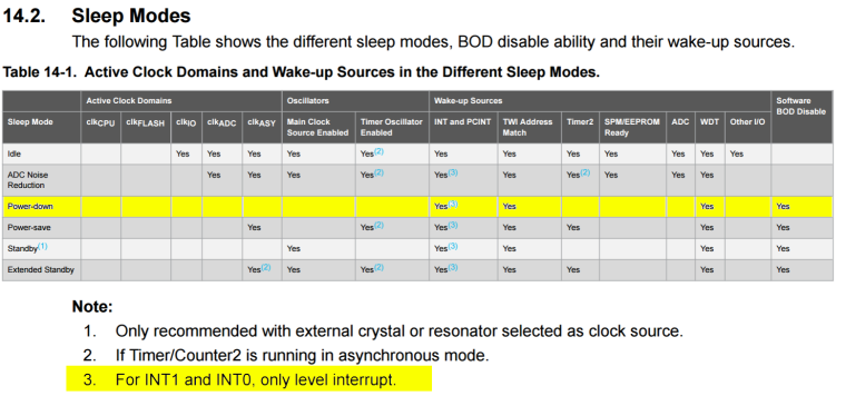
So in our case that's INT and WDT (TWI Address match is for i2c slave implementations).
When a timeout parameter is passed to a sleep() function of the MySensors library the watchdog (WDT) will be used to wake after the specified timeout. If timeout is set to 0 (and wake-up from interrupts is specified) the watchdog will be completely disabled to save some more power.
When an interrupt source is passed to a sleep() function of the library it will configure INT0 and/or INT1 to wake up the ATMega328.
Note point 3, as only level interrupts (more precise LOW in case of ATMega328, thanks @AWI for reminding me) can be used as a wake-up source.
Many posts here use RISING/FALLING/CHANGE as wake-up source for ATMega328 which is not supported by the ATMega328P and thus not supported by the MySensors library. Although people claim it is working for them you are on your own when using the chip out of spec and can expect strange behavior!The datasheet continues in detail on the power-down mode:
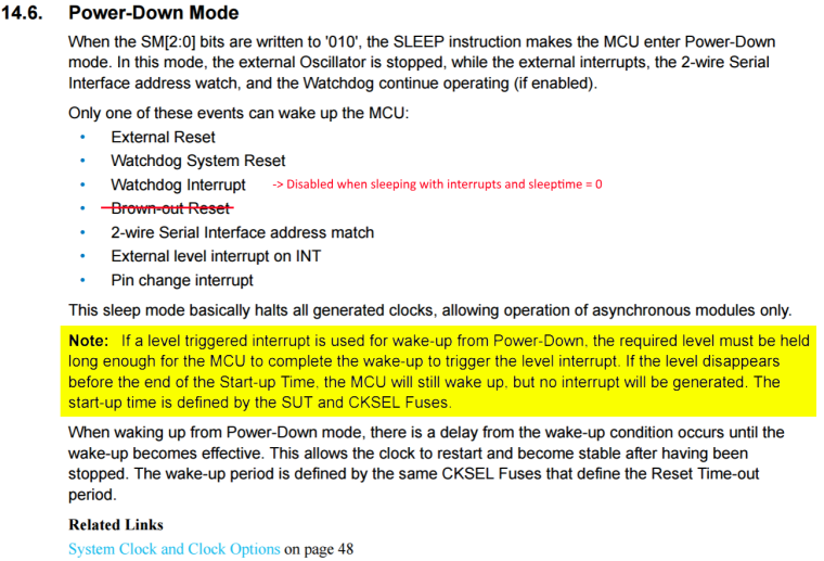
The MySensors library disables brown-out to save some power. Serial interface address match and pin change interrupt are not used by the library.
Pay special attention to the note: Waking the AVR from a INT0/INT1 interrupt will require the LOW level to remain for the startup-time, or the interrupt will not trigger. This means that only when the level is held long enough the library will be able to detect it woke from the external interrupt. If the level is not held at least the startup-time, it will assume it woke because of the total sleep time expired, and return MY_WAKE_UP_BY_TIMER (value -1).This start-up time depends on the clock frequency and fuse bits, which for e.g. an 8MHz Arduino Pro Mini comes down to 2ms.
So just remember: In the MySensors library, only use LOW level interrupts to wake an ATMega328 from sleep and assure the interrupt level remains constant for at least the start-up time!
@AWI Your third example is out-of spec (CHANGE interrupt) and behavior is therefore undefined. If it seems to work, you're lucky...
This information is outdated. An error in the ATMega328P datasheet has been confirmed. See https://forum.mysensors.org/topic/6572/sleep-with-interrupt-only-works-with-level-low
http://yveaux.blogspot.nl
-
This information is outdated. An error in the ATMega328P datasheet has been confirmed. See https://forum.mysensors.org/topic/6572/sleep-with-interrupt-only-works-with-level-low
@AWI Ok, last reply :simple_smile:
I'll have to dwell a little to explain how the AVR works and what its limitations are regarding sleeping, and how the MySensors library handles it.
For AVR architecture, the MySensors library uses the 'Power-Down mode' when sleeping.
I'll focus on ATMega328P here, for which the datasheet states the possible wake-up sources:So in our case that's INT and WDT (TWI Address match is for i2c slave implementations).
When a timeout parameter is passed to a sleep() function of the MySensors library the watchdog (WDT) will be used to wake after the specified timeout. If timeout is set to 0 (and wake-up from interrupts is specified) the watchdog will be completely disabled to save some more power.
When an interrupt source is passed to a sleep() function of the library it will configure INT0 and/or INT1 to wake up the ATMega328.
Note point 3, as only level interrupts (more precise LOW in case of ATMega328, thanks @AWI for reminding me) can be used as a wake-up source.
Many posts here use RISING/FALLING/CHANGE as wake-up source for ATMega328 which is not supported by the ATMega328P and thus not supported by the MySensors library. Although people claim it is working for them you are on your own when using the chip out of spec and can expect strange behavior!The datasheet continues in detail on the power-down mode:
The MySensors library disables brown-out to save some power. Serial interface address match and pin change interrupt are not used by the library.
Pay special attention to the note: Waking the AVR from a INT0/INT1 interrupt will require the LOW level to remain for the startup-time, or the interrupt will not trigger. This means that only when the level is held long enough the library will be able to detect it woke from the external interrupt. If the level is not held at least the startup-time, it will assume it woke because of the total sleep time expired, and return MY_WAKE_UP_BY_TIMER (value -1).This start-up time depends on the clock frequency and fuse bits, which for e.g. an 8MHz Arduino Pro Mini comes down to 2ms.
So just remember: In the MySensors library, only use LOW level interrupts to wake an ATMega328 from sleep and assure the interrupt level remains constant for at least the start-up time!
@AWI Your third example is out-of spec (CHANGE interrupt) and behavior is therefore undefined. If it seems to work, you're lucky...
This information is outdated. An error in the ATMega328P datasheet has been confirmed. See https://forum.mysensors.org/topic/6572/sleep-with-interrupt-only-works-with-level-low
-
@gohan If you sensor signal goes HIGH the moment it detects movement one would sleep until the interrupt has HIGH level.
After sending a message it is important to wait until the signal goes low again before sleeping, otherwise the sensor will wake immediately.http://yveaux.blogspot.nl
-
@gohan If you sensor signal goes HIGH the moment it detects movement one would sleep until the interrupt has HIGH level.
After sending a message it is important to wait until the signal goes low again before sleeping, otherwise the sensor will wake immediately. -
This information is outdated. An error in the ATMega328P datasheet has been confirmed. See https://forum.mysensors.org/topic/6572/sleep-with-interrupt-only-works-with-level-low
@AWI Ok, last reply :simple_smile:
I'll have to dwell a little to explain how the AVR works and what its limitations are regarding sleeping, and how the MySensors library handles it.
For AVR architecture, the MySensors library uses the 'Power-Down mode' when sleeping.
I'll focus on ATMega328P here, for which the datasheet states the possible wake-up sources:So in our case that's INT and WDT (TWI Address match is for i2c slave implementations).
When a timeout parameter is passed to a sleep() function of the MySensors library the watchdog (WDT) will be used to wake after the specified timeout. If timeout is set to 0 (and wake-up from interrupts is specified) the watchdog will be completely disabled to save some more power.
When an interrupt source is passed to a sleep() function of the library it will configure INT0 and/or INT1 to wake up the ATMega328.
Note point 3, as only level interrupts (more precise LOW in case of ATMega328, thanks @AWI for reminding me) can be used as a wake-up source.
Many posts here use RISING/FALLING/CHANGE as wake-up source for ATMega328 which is not supported by the ATMega328P and thus not supported by the MySensors library. Although people claim it is working for them you are on your own when using the chip out of spec and can expect strange behavior!The datasheet continues in detail on the power-down mode:
The MySensors library disables brown-out to save some power. Serial interface address match and pin change interrupt are not used by the library.
Pay special attention to the note: Waking the AVR from a INT0/INT1 interrupt will require the LOW level to remain for the startup-time, or the interrupt will not trigger. This means that only when the level is held long enough the library will be able to detect it woke from the external interrupt. If the level is not held at least the startup-time, it will assume it woke because of the total sleep time expired, and return MY_WAKE_UP_BY_TIMER (value -1).This start-up time depends on the clock frequency and fuse bits, which for e.g. an 8MHz Arduino Pro Mini comes down to 2ms.
So just remember: In the MySensors library, only use LOW level interrupts to wake an ATMega328 from sleep and assure the interrupt level remains constant for at least the start-up time!
@AWI Your third example is out-of spec (CHANGE interrupt) and behavior is therefore undefined. If it seems to work, you're lucky...
This information is outdated. An error in the ATMega328P datasheet has been confirmed. See https://forum.mysensors.org/topic/6572/sleep-with-interrupt-only-works-with-level-low
@Yveaux said in [SOLVED] Sleep dont run:
@AWI Your third example is out-of spec (CHANGE interrupt) and behavior is therefore undefined. If it seems to work, you're lucky...
Are you saying that the example posted here https://www.mysensors.org/build/motion contains mistakes ?
-
@Yveaux said in [SOLVED] Sleep dont run:
@AWI Your third example is out-of spec (CHANGE interrupt) and behavior is therefore undefined. If it seems to work, you're lucky...
Are you saying that the example posted here https://www.mysensors.org/build/motion contains mistakes ?
-
@Yveaux sure, but I would like to avoid having a sleeping node that wakes only with motion and then reports "no motions" only when sleep timeout is reached
-
If you have a motion sensor it will immediately wake when motion is detected but it will report pir sensor change to "no motion" only at sleep timeout, and if timeout is like 30 minutes then the controller will have "motion detected" on for 30 minutes. So unless you make an if statement with two sleep function, one with short sleep if pir sensor is on and one with long sleep if pir sensor is off, you will not be quickly notified of pir state changes
@gohan How about this ?
I think it covers the regular use-case (untested :baby:):#define MY_DEBUG #define MY_RADIO_NRF24 #include <MySensors.h> unsigned long SLEEP_TIME = 10000; #define PIN_PIR (3) MyMessage msg(CHILD_ID, V_TRIPPED); void setup() { pinMode(PIN_PIR, INPUT); // Configure what to send in case the PIR trips msg.set("1"); } void presentation() { sendSketchInfo("Motion Sensor", "1.0"); present(CHILD_ID, S_MOTION); } void loop() { // Sleep until woken by PIR motion, or timeout switch( sleep(digitalPinToInterrupt(PIN_PIR), LOW, SLEEP_TIME) ) { case MY_WAKE_UP_BY_TIMER: Serial.println("Woke up by timer -- do something smart ;-)") break; case MY_SLEEP_NOT_POSSIBLE: Serial.println("Unable to sleep ;-(") break; default: Serial.println("Woke up by PIR -- sound the alarm!") send(msg); // Wait until PIR signal goes low again; poll every 100ms. while( digitalRead(DIGITAL_INPUT_SENSOR) == HIGH ) { sleep(100); } break; } }Note the LOW level to wake the ATMega. Regular PIRs will generate a HIGH level on motion.
Hello! It looks like you're interested in this conversation, but you don't have an account yet.
Getting fed up of having to scroll through the same posts each visit? When you register for an account, you'll always come back to exactly where you were before, and choose to be notified of new replies (either via email, or push notification). You'll also be able to save bookmarks and upvote posts to show your appreciation to other community members.
With your input, this post could be even better 💗
Register Login