RGB LED strip

-
@maghac Great project.
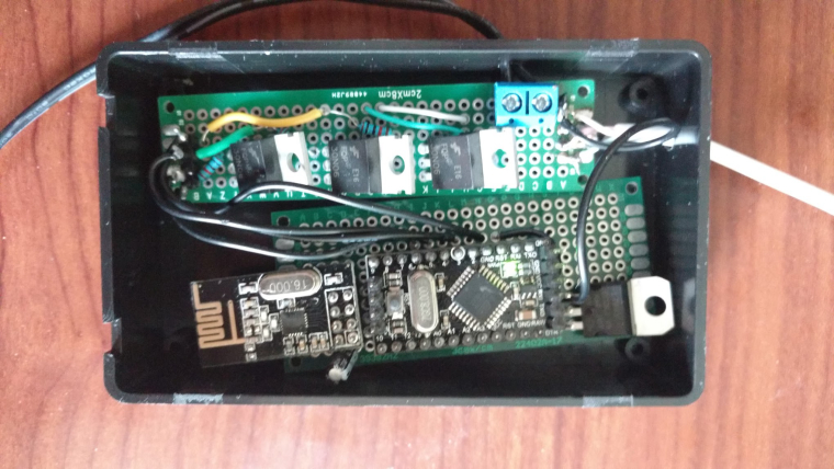
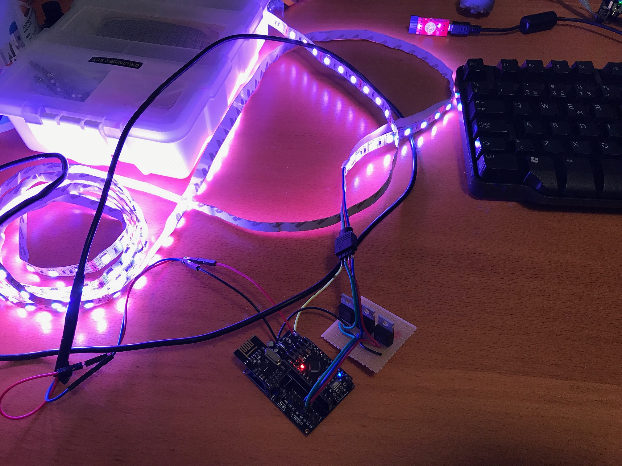
I've made something similar, Arduino Pro Mini 5v, 5m LED strip (non-addressable), nrf24L01+ and MOSTFETs
I know it took me awhile to find code examples, so I figured I would share my code incase it helps anyone else.
I use Domoticz as a controller. This code talks to:
- Switch - to control turning my color cycle fade effect on
- Dimmer - to control the speed of the color cycle fade effect
- RGB switch - to control having only a single color turned on and the brightness of the string.
Much of my code is standard stuff, using FastLED analogue, but I'm particularly proud of the brightness part, since I bashed my head against the keyboard several times trying to figure it out
//## INCLUDES ##
#define MY_DEBUG
#define MY_RADIO_NRF24
#define MY_NODE_ID 20

#include <MySensors.h>
#include <SPI.h>
#include <FastLED.h>

#define cID_RGB_SELECTOR 0
#define cID_CYCLE_EFFECT 1
#define cID_CYCLE_EFFECT_SPEED 2

#define PIN_RED   5
#define PIN_GREEN 6
#define PIN_BLUE  3

//## VARIABLES ##
// MySensors
#define MySensors_SketchName      "RGB LED Strip"
#define MySensors_SketchVersion   "v0.3"
MyMessage MySensors_MSG_Last_Color(cID_RGB_SELECTOR,V_VAR1);
MyMessage MySensors_MSG_RGB_Selector(cID_RGB_SELECTOR, V_LIGHT);
MyMessage MySeonsors_MSG_CYCLE_EFFECT(cID_CYCLE_EFFECT, V_LIGHT);
MyMessage MySensors_MSG_CYCLE_EFFECT_SPEED(cID_CYCLE_EFFECT_SPEED, V_DIMMER);
bool MySensors_RequestACK = false;
// Single color
int Solid_RGB_Active=0;
char Solid_RGB_Color[] = "000000";
uint16_t Solid_RGB_Brightness = 0xFF;
// Cycle effect
int Cycle_Effect_Active=0;
unsigned long Cycle_Effect_pMillis = 0;
long Cycle_Effect_Speed = 20;
static uint8_t Cycle_Effect_Current_Hue;
// Supporting
bool Status_Change = false;
bool Print_Debug = false;

// ## Primary flow control
void setup() {
  Serial.begin(115200);
  while (!Serial) ;
  Serial.print("compiled: ");Serial.print(__DATE__);Serial.println(__TIME__);

  pinMode(PIN_RED,   OUTPUT);
  pinMode(PIN_GREEN, OUTPUT);
  pinMode(PIN_BLUE,  OUTPUT);

  Event_ColorTestBars();

  request(cID_RGB_SELECTOR, V_VAR1);
  request(cID_RGB_SELECTOR, V_LIGHT);
  request(cID_CYCLE_EFFECT, V_LIGHT);
  request(cID_CYCLE_EFFECT_SPEED, V_DIMMER);
}
void loop() {
  if (Cycle_Effect_Active == 1){
    unsigned long currentMillis = millis();
    Event_RunCycleEffect(currentMillis);
  } else if (Status_Change){
    Status_Change = false;
      #ifdef MY_DEBUG
        if (Print_Debug) {Serial.println("STATUS CHANGE");}
      #endif
    if (Solid_RGB_Active == 0){
      Event_SetLEDColors( CRGB::Black );
    }else if (Solid_RGB_Active == 1){
      CHSV colorHSV = rgb2hsv_approximate(str2CRGB(Solid_RGB_Color));
      Event_SetLEDColors(CHSV(colorHSV.h, colorHSV.s, Solid_RGB_Brightness));
    }
  }
}
// ## MySensors Methods
void presentation()  {
  sendSketchInfo(MySensors_SketchName, MySensors_SketchVersion);

  present(cID_RGB_SELECTOR, S_RGB_LIGHT, "RGB Color Selector", MySensors_RequestACK);
  present(cID_CYCLE_EFFECT, S_LIGHT, "RGB Cycle Effect", MySensors_RequestACK);
  present(cID_CYCLE_EFFECT_SPEED, S_DIMMER, "RGB Cycle Effect Speed", MySensors_RequestACK);
}
void receive(const MyMessage &message){
  #ifdef MY_DEBUG
    if (message.isAck()){
      Serial.println("Got ack from gateway");
    }
  #endif
  if (message.type == V_LIGHT){
    #ifdef MY_DEBUG
      if (Print_Debug) {Serial.println("message v_light");}
    #endif
    int current_Light_State = message.getString()[0] == '1';// Incoming on/off command sent from controller ("1" or "0")
    if (message.sensor==cID_CYCLE_EFFECT){// is Cycle Message
      if (current_Light_State==1){//turn cycle on
        Event_LightCycle(true, true, false);
        Event_SolidColor(false, false, true);
      } else {//turn cycle off
        Event_LightCycle(false, true, false);
        Event_SolidColor(false, false, true);
      }
    } else if (message.sensor==cID_RGB_SELECTOR){// is RGB Message
      if (current_Light_State==1){//turn RGB on
        Event_SolidColor(true, true, false);
        Event_LightCycle(false, false, true);
      } else {//turn RGB off
        Event_SolidColor(false, true, false);
        Event_LightCycle(false, false, true);
      }
    } else {
      #ifdef MY_DEBUG
        Serial.print("UNKNOWN Light - Message:");
        Serial.print(message.getString());
        Serial.print(" - Sensor:");
        Serial.println(message.sensor);
      #endif
    }
  } else if (message.type == V_RGB){
    #ifdef MY_DEBUG
      if (Print_Debug) {Serial.println("message v_rgb");}
    #endif
    String szMessage=message.getString();
    strcpy(Solid_RGB_Color, getValue(szMessage,'&',0).c_str());
    Solid_RGB_Active = 1;
  }else if (message.type == V_DIMMER) {// if DIMMER type, adjust brightness
    #ifdef MY_DEBUG
      if (Print_Debug) {Serial.println("message v_dimmer");}
    #endif
    if (message.sensor==cID_RGB_SELECTOR){// is single Message
      if (Solid_RGB_Active==1){//turn RGB on
        Event_SolidColor(true, true, false);
        Event_LightCycle(false, false, true);
      } else {//turn RGB off
        Event_SolidColor(false, true, false);
        Event_LightCycle(false, false, true);
      }
      Solid_RGB_Brightness = map(message.getLong(), 0, 100, 0, 255);
      CRGB colorRGB = str2CRGB(Solid_RGB_Color);
      CHSV colorHSV = rgb2hsv_approximate(colorRGB);
      colorHSV = CHSV(colorHSV.h, colorHSV.s, Solid_RGB_Brightness);
      Event_SetLEDColors(colorHSV);
      #ifdef MY_DEBUG
        if (Print_Debug) {
          Serial.print("colorHSV.h:");
          Serial.println(colorHSV.h);
          Serial.print("colorHSV.s:");
          Serial.println(colorHSV.s);
          Serial.print("colorHSV.v:");
          Serial.println(colorHSV.v);
        }
      #endif
      Event_SendLastColor();
    } else if (message.sensor==cID_CYCLE_EFFECT_SPEED){// is Speed dimmer Message
      Cycle_Effect_Speed = map(message.getLong(), 0, 100, 1, 202);
      #ifdef MY_DEBUG
        if (Print_Debug) {
          Serial.print("Cycle_Effect_Speed: ");
          Serial.println(Cycle_Effect_Speed);
        }
      #endif
    }
  }else if (message.type == V_STATUS) {           // if on/off type, toggle brightness
    #ifdef MY_DEBUG
      if (Print_Debug) {Serial.println("message v_status");}
    #endif
    Solid_RGB_Active = message.getInt();
    Cycle_Effect_Active = 0;
    if (Solid_RGB_Active == 0){
      if (Print_Debug) {Serial.println("Strip OFF");}
      Event_SetLEDColors( CRGB::Black );
    }else{
      if (Print_Debug) {Serial.println("Strip ON");}
      Event_SetLEDColors(strtol(Solid_RGB_Color, NULL, 16));
    }
    //Event_SendLastColor();
  }else if (message.type==V_VAR1) {            // color status
    String szMessage=message.getString();
    #ifdef MY_DEBUG
      if (Print_Debug) {
        Serial.println("message v_var1");
        Serial.println(szMessage);
      }
    #endif
    strcpy(Solid_RGB_Color, getValue(szMessage,'&',0).c_str());
    Solid_RGB_Active = 1;
    Cycle_Effect_Active = 0;
  }
  Status_Change = true;
}
// ## Events
void Event_LightCycle(bool t, bool s, bool u) {
  Cycle_Effect_Active = (t) ? 1 : 0;
  if (u){
    send(MySeonsors_MSG_CYCLE_EFFECT.set(Cycle_Effect_Active),MySensors_RequestACK);
  }
}
void Event_SolidColor(bool t, bool s, bool u) {
  Solid_RGB_Active = (t) ? 1 : 0;
  if (u){
    send(MySensors_MSG_RGB_Selector.set(Solid_RGB_Active),MySensors_RequestACK);
  }
}
void Event_SetLEDColors( const CRGB& rgb){
  analogWrite(PIN_RED,   rgb.r );
  analogWrite(PIN_GREEN, rgb.g );
  analogWrite(PIN_BLUE,  rgb.b );
}
void Event_SendLastColor(){
  String current_status=Solid_RGB_Color+String("&")+String(Solid_RGB_Brightness)+String("&")+String(Solid_RGB_Active);
  send(MySensors_MSG_Last_Color.set(current_status.c_str()),MySensors_RequestACK);
}
void Event_RunCycleEffect(unsigned long theMills){
  if (theMills - Cycle_Effect_pMillis >= Cycle_Effect_Speed){
    Cycle_Effect_pMillis = theMills;
    Cycle_Effect_Current_Hue = Cycle_Effect_Current_Hue + 1;
    Event_SetLEDColors( CHSV( Cycle_Effect_Current_Hue, 255, 255) );
  }
}
void Event_ColorTestBars(){// Event_ColorTestBars: flashes Red, then Green, then Blue, then Black. Helpful for diagnosing if you've mis-wired which is which.
  Event_SetLEDColors( CRGB::Red );   delay(500);
  Event_SetLEDColors( CRGB::Green ); delay(500);
  Event_SetLEDColors( CRGB::Blue );  delay(500);
  Event_SetLEDColors( CRGB::Black ); delay(500);
}
// ## Helper Functions
String getValue(String data, char separator, int index){
 int found = 0;
  int strIndex[] = {0, -1};
  int maxIndex = data.length()-1;
  for(int i=0; i<=maxIndex && found<=index; i++){
    if(data.charAt(i)==separator || i==maxIndex){
      found++;
      strIndex[0] = strIndex[1]+1;
      strIndex[1] = (i == maxIndex) ? i+1 : i;
    }
  }
  return found>index ? data.substring(strIndex[0], strIndex[1]) : "";
}
int x2i(char *s) {
  int x = 0;
  for(;;) {
    char c = *s;
    if (c >= '0' && c <= '9') {
      x *= 16;
      x += c - '0';
    }else if (c >= 'A' && c <= 'F') {
      x *= 16;
      x += (c - 'A') + 10;
    }else {
      break;
    }
    s++;
  }
  return x;
}
char* str2char(String command){
    if(command.length()!=0){
        char *p = const_cast<char*>(command.c_str());
        return p;
    }
}
CRGB str2CRGB(String s){
  String r = str2char(s.substring(0,2));
  String g = str2char(s.substring(2,4));
  String b = str2char(s.substring(4,6));
  uint8_t red = x2i(r.c_str());
  uint8_t green = x2i(g.c_str());
  uint8_t blue = x2i(b.c_str());
  #ifdef MY_DEBUG
    if (Print_Debug) {
      Serial.print("r:");
      Serial.println(r);
      Serial.print("g:");
      Serial.println(g);
      Serial.print("b:");
      Serial.println(b);
      Serial.print("red:");
      Serial.println(red);
      Serial.print("green:");
      Serial.println(green);
      Serial.print("blue:");
      Serial.println(blue);
    }
  #endif
  CRGB colorRGB = CRGB(red, green, blue);
  return colorRGB;
}
Hopefully this proves useful to someone :)
-
Thanks. Will await eagerly for v1.8 as it seems this is the only great RGB code left for mysensors
@moskovskiy82 I'll see if I'll have time to work on it this week, I'll post an update when I have something.
-
@moskovskiy82 I'll see if I'll have time to work on it this week, I'll post an update when I have something.
Hello
I need some help !I've ordered few IRLZ44N Mosfets to play with Dimmable LED Actuator project.
Adafruit RGB LED stripe uses IRLB8721
Could You please tell me if I could use mentioned IRLZ instead of IRLB in case of described RGB project ?Thank You in advance.
-
@Plantex
In my opinion that should work just fine. The specs are fairly similar. I am using the IRLZ44N myself to drive a five meter long RGBW LED-strip and they do not get warm, even without a heat sink. Total current consumption at 24V is just above 2A when all LEDs are lit.
Schematics below:
0_1511539204888_LEDstrip_sch.pdf -
Great project! I could use some help getting this to work. I am using the newbie PCB, just a regular RGB LED for testing and Homeassistant as my controller. Hass adopts the node but I get this error message everytime I restart the node and the switch does not appear on my frontend.
"Not a valid message: Not valid message sub-type: 40 for dictionary value @ data['sub_type']"
I am running '2.0' in my hass config file. I have tried '2.1.' and '2.1.1' with no success. Homeassistant version .60.
I have several temperature sensor nodes talking to hass just fine. Any ideas? I assume I am just missing something simple as I am relatively new to homeassistant and mysensors.
Thank you in advance for your help!
-
@moskovskiy82 I'll see if I'll have time to work on it this week, I'll post an update when I have something.
Well, it took some time, but here is v1.8 at last!
I have modified the code to handle RGBW strips, since I realized that the white light from RGB strips is very uncomfortable and not really suitable for general illumination. It should be fairly easy to convert it back to RGB though. Adding the W channel means that I now need 4 PWM pins, and therefore it was necessary to redefine one of the pins that the radio is connected to - the sketch now expects CE to be connected to pin 8 instead of 9 which is the default (a pro mini only has 3 free PWM pins if you use the default setup).
I've also completely changed now programs/modes are implemented so it should be easier to add new programs. Feel free to experiment with this and let me know what you think.
/** * This program is free software; you can redistribute it and/or * modify it under the terms of the GNU General Public License * version 2 as published by the Free Software Foundation. * * LED STRIP sketch for Mysensors ******************************* * * REVISION HISTORY * 1.0 * Based on the example sketch in mysensors * 1.1 * prgspeed parameter (send as V_VAR1 message) * HomeAssistant compatible (send status to ack) * 1.2 * OTA support * 1.3 * Power-on self test * 1.4 * Bug fix * 1.5 * Other default values * 1.6 * Repeater feature * 1.7 * Multitasking. Alarm and RELAX modes. * 1.8 * Reengineered programs/modes logic. * RGBW variant. Requires 4 PWM pins, so we need to move use a different pin for one of radio connections. */ #define MY_OTA_FIRMWARE_FEATURE // #define MY_REPEATER_FEATURE #define MY_NODE_ID AUTO #define MY_RADIO_NRF24 //#define MY_DEBUG // Normally the radio uses pin 9 for CE #define MY_RF24_CE_PIN 8 #include <MySensors.h> #define CHILD_ID_LIGHT 1 #define SN "LED Strip" #define SV "1.8" MyMessage lightMsg(CHILD_ID_LIGHT, V_LIGHT); MyMessage rgbwMsg(CHILD_ID_LIGHT, V_RGBW); MyMessage dimmerMsg(CHILD_ID_LIGHT, V_DIMMER); MyMessage prgspeedMsg(CHILD_ID_LIGHT, V_VAR1); MyMessage programMsg(CHILD_ID_LIGHT, V_VAR2); #define RR 0 #define GG 1 #define BB 2 #define WW 3 byte current[] = {255, 255, 255, 255}; byte target[] = {255, 255, 255, 255}; byte save[] = {0, 0, 0, 0}; byte temp[] = {0, 0, 0, 0}; float delta[] = {0.0, 0.0, 0.0, 0.0}; char rgbwstring[] = "000000ff"; int on_off_status = 0; int dimmerlevel = 100; int prgspeed = 20; unsigned long last_update = 0; unsigned long tick_length = 5; int fade_step = 0; int program_timer; int program_cycle; int program_step; // Make sure these are PWM pins #define REDPIN 6 #define GREENPIN 5 #define BLUEPIN 3 #define WHITEPIN 9 #define LIGHT_NORMAL 0 #define LIGHT_FADING 1 #define PROGRAM_NOP 0 int light_mode = LIGHT_NORMAL; int program_mode = PROGRAM_NOP; #define SET 0 #define SET_AND_WAIT 1 #define SET_RANDOM 2 #define SET_RANDOM_AND_WAIT 3 #define FADE 4 #define FADE_RANDOM 5 #define WAIT 6 typedef struct rgb_cmd { byte cmd; int p; byte rgbw[4]; } rgb_cmd; rgb_cmd program_ALARM[] = { {SET_AND_WAIT, 25, {255, 255, 255, 0}}, {SET_AND_WAIT, 25, {0, 0, 0, 0}}, {SET_AND_WAIT, 25, {0, 0, 0, 255}}, {SET_AND_WAIT, 25, {0, 0, 0, 0}} }; rgb_cmd program_RELAX[] = { {FADE, 1000, {255, 32, 0, 0}}, {FADE, 1000, {255, 32, 16, 0}}, {FADE, 1000, {255, 16, 32, 0}}, {FADE, 1000, {255, 128, 0, 0}}, {FADE, 1000, {255, 32, 0, 0}}, {FADE, 1000, {255, 32, 32, 0}}, {FADE, 1000, {255, 0, 32, 0}} }; rgb_cmd program_PARTY[] = { {SET_AND_WAIT, 10, {255, 0, 0, 0}}, {SET_AND_WAIT, 10, {0, 0, 0, 255}}, {SET_AND_WAIT, 10, {255, 0, 0, 0}}, {SET_AND_WAIT, 10, {0, 0, 0, 255}}, {SET_AND_WAIT, 10, {255, 0, 0,0}}, {SET_AND_WAIT, 10, {0, 0, 0, 255}}, {SET_AND_WAIT, 10, {255, 0, 0,0}}, {SET_AND_WAIT, 10, {0, 0, 0, 255}}, {SET_AND_WAIT, 10, {255, 0, 0, 0}}, {SET_AND_WAIT, 10, {0, 0, 0, 255}}, {FADE_RANDOM, 50, {255, 255, 255, 0}}, {FADE_RANDOM, 50, {255, 255, 255, 0}}, {FADE_RANDOM, 50, {255, 255, 255, 0}}, {FADE_RANDOM, 50, {255, 255, 255, 0}}, {SET_AND_WAIT, 50, {0, 0, 255, 0}}, {SET_AND_WAIT, 50, {0, 255, 255 ,0}}, {SET_AND_WAIT, 50, {255, 255, 0, 0}}, {SET_AND_WAIT, 50, {0, 255, 0, 0}}, {FADE_RANDOM, 50, {255, 255, 255, 0}}, {FADE_RANDOM, 50, {255, 255, 255, 0}}, {FADE_RANDOM, 50, {255, 255, 255, 0}}, {FADE_RANDOM, 50, {255, 255, 255, 0}}, {FADE_RANDOM, 50, {255, 255, 255, 0}} }; rgb_cmd* programs[] = { &program_ALARM[0], &program_RELAX[0], &program_PARTY[0] }; const int program_steps[] = { sizeof(program_ALARM)/sizeof(rgb_cmd), 7, 22 }; void setup() { // Fix the PWM timer. Without this the LEDs will flicker. TCCR0A = _BV(COM0A1) | _BV(COM0B1) | _BV(WGM00); // Output pins pinMode(REDPIN, OUTPUT); pinMode(GREENPIN, OUTPUT); pinMode(BLUEPIN, OUTPUT); pinMode(WHITEPIN, OUTPUT); } void presentation() { // Send the Sketch Version Information to the Gateway sendSketchInfo(SN, SV); present(CHILD_ID_LIGHT, S_RGBW_LIGHT); } void selftest() { on_off_status = 1; current[RR] = 255; current[GG] = 0; current[BB] = 0; current[WW] = 0; set_hw_status(); wait(200); current[RR] = 0; current[GG] = 255; set_hw_status(); wait(200); current[GG] = 0; current[BB] = 255; set_hw_status(); wait(200); current[BB] = 0; current[WW] = 255; set_hw_status(); wait(200); current[RR] = 0; current[GG] = 0; current[BB] = 0; set_hw_status(); wait(200); on_off_status = 0; } void loop() { static bool first_message_sent = false; if ( first_message_sent == false ) { selftest(); set_hw_status(); send(rgbwMsg.set(rgbwstring)); send(lightMsg.set(on_off_status)); send(dimmerMsg.set(dimmerlevel)); send(prgspeedMsg.set(prgspeed)); send(programMsg.set(program_mode)); first_message_sent = true; } unsigned long now = millis(); // Maybe we wrapped around? Then reset last_update to 0. if (now < last_update) { last_update = 0; } if (now - last_update > tick_length) { last_update = now; // If we're fading, finish that before we do anything else if (light_mode == LIGHT_FADING) { calc_fade(); } else { if (program_mode > PROGRAM_NOP) { handle_program(); } } } set_hw_status(); } void receive(const MyMessage &message) { int val; if (message.type == V_RGBW) { for (int i=0; i<=3; i++) { temp[i] = hextoint(message.data[i*2]) * 16 + hextoint(message.data[i*2+1]); } // Save old value strcpy(rgbwstring, message.data); init_fade(prgspeed, temp); send(rgbwMsg.set(rgbwstring)); } else if (message.type == V_LIGHT || message.type == V_STATUS) { val = atoi(message.data); if (val == 0 or val == 1) { on_off_status = val; send(lightMsg.set(on_off_status)); } } else if (message.type == V_PERCENTAGE) { val = atoi(message.data); if (val >= 0 and val <=100) { dimmerlevel = val; send(dimmerMsg.set(dimmerlevel)); } } else if (message.type == V_VAR1 ) { val = atoi(message.data); if (val >= 0 and val <= 2000) { prgspeed = val; send(prgspeedMsg.set(val)); } } else if (message.type == V_VAR2 ) { val = atoi(message.data); if (val == PROGRAM_NOP) { stop_program(); send(programMsg.set(val)); } else { init_program(val); send(programMsg.set(val)); } } else { return; } } void execute_step(rgb_cmd cmd) { if (cmd.cmd == SET) { set_rgb(cmd.rgbw); } else if (cmd.cmd == SET_AND_WAIT) { set_rgb(cmd.rgbw); program_timer = cmd.p; } else if (cmd.cmd == SET_RANDOM) { set_rgb_random(cmd.rgbw); } else if (cmd.cmd == SET_RANDOM_AND_WAIT) { set_rgb_random(cmd.rgbw); program_timer = cmd.p; } else if (cmd.cmd == FADE) { init_fade(cmd.p, cmd.rgbw); } else if (cmd.cmd == FADE_RANDOM) { init_fade_random(cmd.p, cmd.rgbw); } else if (cmd.cmd == WAIT) { program_timer = cmd.p; } } void init_program(int program) { program_mode = program; program_step = 0; program_timer = 0; save_state(); execute_step(programs[program_mode-1][0]); } void handle_program() { if (program_timer > 0) { program_timer--; } if (program_timer == 0) { program_step++; if (program_step == program_steps[program_mode-1]) { program_step = 0; } execute_step(programs[program_mode-1][program_step]); } } void stop_program() { restore_state(); light_mode = LIGHT_NORMAL; program_mode = PROGRAM_NOP; } void save_state() { memcpy(save, current, 4 ); } void restore_state() { memcpy(current, save, 4 ); } void set_rgb (byte rgbw[]) { light_mode = LIGHT_NORMAL; memcpy(current, rgbw, 4); } void set_rgb_random (byte rgbw[]) { light_mode = LIGHT_NORMAL; for (int i=0; i <= 3; i++){ current[i] = random(rgbw[i]); } } void init_fade(int t, byte rgbw[]) { light_mode = LIGHT_FADING; fade_step = t; memcpy(target, rgbw, 4); for (int i=0; i<=3; i++) { delta[i] = (target[i] - current[i]) / float(fade_step); } } void init_fade_random(int t, byte rgbw[]) { light_mode = LIGHT_FADING; fade_step = t; for (int i=0; i<=3; i++) { target[i] = random(rgbw[i]); delta[i] = (target[i] - current[i]) / float(fade_step); } } void calc_fade() { if (fade_step > 0) { fade_step--; for (int i=0; i<=3; i++) { current[i] = target[i] - delta[i] * fade_step; } } else { light_mode = LIGHT_NORMAL; } } void set_hw_status() { analogWrite(REDPIN, on_off_status * (int)(current[RR] * dimmerlevel/100.0)); analogWrite(GREENPIN, on_off_status * (int)(current[GG] * dimmerlevel/100.0)); analogWrite(BLUEPIN, on_off_status * (int)(current[BB] * dimmerlevel/100.0)); analogWrite(WHITEPIN, on_off_status * (int)(current[WW] * dimmerlevel/100.0)); } byte hextoint (byte c) { if ((c >= '0') && (c <= '9')) return c - '0'; if ((c >= 'A') && (c <= 'F')) return c - 'A' + 10; if ((c >= 'a') && (c <= 'f')) return c - 'a' + 10; return 0; } -
Well, it took some time, but here is v1.8 at last!
I have modified the code to handle RGBW strips, since I realized that the white light from RGB strips is very uncomfortable and not really suitable for general illumination. It should be fairly easy to convert it back to RGB though. Adding the W channel means that I now need 4 PWM pins, and therefore it was necessary to redefine one of the pins that the radio is connected to - the sketch now expects CE to be connected to pin 8 instead of 9 which is the default (a pro mini only has 3 free PWM pins if you use the default setup).
I've also completely changed now programs/modes are implemented so it should be easier to add new programs. Feel free to experiment with this and let me know what you think.
/** * This program is free software; you can redistribute it and/or * modify it under the terms of the GNU General Public License * version 2 as published by the Free Software Foundation. * * LED STRIP sketch for Mysensors ******************************* * * REVISION HISTORY * 1.0 * Based on the example sketch in mysensors * 1.1 * prgspeed parameter (send as V_VAR1 message) * HomeAssistant compatible (send status to ack) * 1.2 * OTA support * 1.3 * Power-on self test * 1.4 * Bug fix * 1.5 * Other default values * 1.6 * Repeater feature * 1.7 * Multitasking. Alarm and RELAX modes. * 1.8 * Reengineered programs/modes logic. * RGBW variant. Requires 4 PWM pins, so we need to move use a different pin for one of radio connections. */ #define MY_OTA_FIRMWARE_FEATURE // #define MY_REPEATER_FEATURE #define MY_NODE_ID AUTO #define MY_RADIO_NRF24 //#define MY_DEBUG // Normally the radio uses pin 9 for CE #define MY_RF24_CE_PIN 8 #include <MySensors.h> #define CHILD_ID_LIGHT 1 #define SN "LED Strip" #define SV "1.8" MyMessage lightMsg(CHILD_ID_LIGHT, V_LIGHT); MyMessage rgbwMsg(CHILD_ID_LIGHT, V_RGBW); MyMessage dimmerMsg(CHILD_ID_LIGHT, V_DIMMER); MyMessage prgspeedMsg(CHILD_ID_LIGHT, V_VAR1); MyMessage programMsg(CHILD_ID_LIGHT, V_VAR2); #define RR 0 #define GG 1 #define BB 2 #define WW 3 byte current[] = {255, 255, 255, 255}; byte target[] = {255, 255, 255, 255}; byte save[] = {0, 0, 0, 0}; byte temp[] = {0, 0, 0, 0}; float delta[] = {0.0, 0.0, 0.0, 0.0}; char rgbwstring[] = "000000ff"; int on_off_status = 0; int dimmerlevel = 100; int prgspeed = 20; unsigned long last_update = 0; unsigned long tick_length = 5; int fade_step = 0; int program_timer; int program_cycle; int program_step; // Make sure these are PWM pins #define REDPIN 6 #define GREENPIN 5 #define BLUEPIN 3 #define WHITEPIN 9 #define LIGHT_NORMAL 0 #define LIGHT_FADING 1 #define PROGRAM_NOP 0 int light_mode = LIGHT_NORMAL; int program_mode = PROGRAM_NOP; #define SET 0 #define SET_AND_WAIT 1 #define SET_RANDOM 2 #define SET_RANDOM_AND_WAIT 3 #define FADE 4 #define FADE_RANDOM 5 #define WAIT 6 typedef struct rgb_cmd { byte cmd; int p; byte rgbw[4]; } rgb_cmd; rgb_cmd program_ALARM[] = { {SET_AND_WAIT, 25, {255, 255, 255, 0}}, {SET_AND_WAIT, 25, {0, 0, 0, 0}}, {SET_AND_WAIT, 25, {0, 0, 0, 255}}, {SET_AND_WAIT, 25, {0, 0, 0, 0}} }; rgb_cmd program_RELAX[] = { {FADE, 1000, {255, 32, 0, 0}}, {FADE, 1000, {255, 32, 16, 0}}, {FADE, 1000, {255, 16, 32, 0}}, {FADE, 1000, {255, 128, 0, 0}}, {FADE, 1000, {255, 32, 0, 0}}, {FADE, 1000, {255, 32, 32, 0}}, {FADE, 1000, {255, 0, 32, 0}} }; rgb_cmd program_PARTY[] = { {SET_AND_WAIT, 10, {255, 0, 0, 0}}, {SET_AND_WAIT, 10, {0, 0, 0, 255}}, {SET_AND_WAIT, 10, {255, 0, 0, 0}}, {SET_AND_WAIT, 10, {0, 0, 0, 255}}, {SET_AND_WAIT, 10, {255, 0, 0,0}}, {SET_AND_WAIT, 10, {0, 0, 0, 255}}, {SET_AND_WAIT, 10, {255, 0, 0,0}}, {SET_AND_WAIT, 10, {0, 0, 0, 255}}, {SET_AND_WAIT, 10, {255, 0, 0, 0}}, {SET_AND_WAIT, 10, {0, 0, 0, 255}}, {FADE_RANDOM, 50, {255, 255, 255, 0}}, {FADE_RANDOM, 50, {255, 255, 255, 0}}, {FADE_RANDOM, 50, {255, 255, 255, 0}}, {FADE_RANDOM, 50, {255, 255, 255, 0}}, {SET_AND_WAIT, 50, {0, 0, 255, 0}}, {SET_AND_WAIT, 50, {0, 255, 255 ,0}}, {SET_AND_WAIT, 50, {255, 255, 0, 0}}, {SET_AND_WAIT, 50, {0, 255, 0, 0}}, {FADE_RANDOM, 50, {255, 255, 255, 0}}, {FADE_RANDOM, 50, {255, 255, 255, 0}}, {FADE_RANDOM, 50, {255, 255, 255, 0}}, {FADE_RANDOM, 50, {255, 255, 255, 0}}, {FADE_RANDOM, 50, {255, 255, 255, 0}} }; rgb_cmd* programs[] = { &program_ALARM[0], &program_RELAX[0], &program_PARTY[0] }; const int program_steps[] = { sizeof(program_ALARM)/sizeof(rgb_cmd), 7, 22 }; void setup() { // Fix the PWM timer. Without this the LEDs will flicker. TCCR0A = _BV(COM0A1) | _BV(COM0B1) | _BV(WGM00); // Output pins pinMode(REDPIN, OUTPUT); pinMode(GREENPIN, OUTPUT); pinMode(BLUEPIN, OUTPUT); pinMode(WHITEPIN, OUTPUT); } void presentation() { // Send the Sketch Version Information to the Gateway sendSketchInfo(SN, SV); present(CHILD_ID_LIGHT, S_RGBW_LIGHT); } void selftest() { on_off_status = 1; current[RR] = 255; current[GG] = 0; current[BB] = 0; current[WW] = 0; set_hw_status(); wait(200); current[RR] = 0; current[GG] = 255; set_hw_status(); wait(200); current[GG] = 0; current[BB] = 255; set_hw_status(); wait(200); current[BB] = 0; current[WW] = 255; set_hw_status(); wait(200); current[RR] = 0; current[GG] = 0; current[BB] = 0; set_hw_status(); wait(200); on_off_status = 0; } void loop() { static bool first_message_sent = false; if ( first_message_sent == false ) { selftest(); set_hw_status(); send(rgbwMsg.set(rgbwstring)); send(lightMsg.set(on_off_status)); send(dimmerMsg.set(dimmerlevel)); send(prgspeedMsg.set(prgspeed)); send(programMsg.set(program_mode)); first_message_sent = true; } unsigned long now = millis(); // Maybe we wrapped around? Then reset last_update to 0. if (now < last_update) { last_update = 0; } if (now - last_update > tick_length) { last_update = now; // If we're fading, finish that before we do anything else if (light_mode == LIGHT_FADING) { calc_fade(); } else { if (program_mode > PROGRAM_NOP) { handle_program(); } } } set_hw_status(); } void receive(const MyMessage &message) { int val; if (message.type == V_RGBW) { for (int i=0; i<=3; i++) { temp[i] = hextoint(message.data[i*2]) * 16 + hextoint(message.data[i*2+1]); } // Save old value strcpy(rgbwstring, message.data); init_fade(prgspeed, temp); send(rgbwMsg.set(rgbwstring)); } else if (message.type == V_LIGHT || message.type == V_STATUS) { val = atoi(message.data); if (val == 0 or val == 1) { on_off_status = val; send(lightMsg.set(on_off_status)); } } else if (message.type == V_PERCENTAGE) { val = atoi(message.data); if (val >= 0 and val <=100) { dimmerlevel = val; send(dimmerMsg.set(dimmerlevel)); } } else if (message.type == V_VAR1 ) { val = atoi(message.data); if (val >= 0 and val <= 2000) { prgspeed = val; send(prgspeedMsg.set(val)); } } else if (message.type == V_VAR2 ) { val = atoi(message.data); if (val == PROGRAM_NOP) { stop_program(); send(programMsg.set(val)); } else { init_program(val); send(programMsg.set(val)); } } else { return; } } void execute_step(rgb_cmd cmd) { if (cmd.cmd == SET) { set_rgb(cmd.rgbw); } else if (cmd.cmd == SET_AND_WAIT) { set_rgb(cmd.rgbw); program_timer = cmd.p; } else if (cmd.cmd == SET_RANDOM) { set_rgb_random(cmd.rgbw); } else if (cmd.cmd == SET_RANDOM_AND_WAIT) { set_rgb_random(cmd.rgbw); program_timer = cmd.p; } else if (cmd.cmd == FADE) { init_fade(cmd.p, cmd.rgbw); } else if (cmd.cmd == FADE_RANDOM) { init_fade_random(cmd.p, cmd.rgbw); } else if (cmd.cmd == WAIT) { program_timer = cmd.p; } } void init_program(int program) { program_mode = program; program_step = 0; program_timer = 0; save_state(); execute_step(programs[program_mode-1][0]); } void handle_program() { if (program_timer > 0) { program_timer--; } if (program_timer == 0) { program_step++; if (program_step == program_steps[program_mode-1]) { program_step = 0; } execute_step(programs[program_mode-1][program_step]); } } void stop_program() { restore_state(); light_mode = LIGHT_NORMAL; program_mode = PROGRAM_NOP; } void save_state() { memcpy(save, current, 4 ); } void restore_state() { memcpy(current, save, 4 ); } void set_rgb (byte rgbw[]) { light_mode = LIGHT_NORMAL; memcpy(current, rgbw, 4); } void set_rgb_random (byte rgbw[]) { light_mode = LIGHT_NORMAL; for (int i=0; i <= 3; i++){ current[i] = random(rgbw[i]); } } void init_fade(int t, byte rgbw[]) { light_mode = LIGHT_FADING; fade_step = t; memcpy(target, rgbw, 4); for (int i=0; i<=3; i++) { delta[i] = (target[i] - current[i]) / float(fade_step); } } void init_fade_random(int t, byte rgbw[]) { light_mode = LIGHT_FADING; fade_step = t; for (int i=0; i<=3; i++) { target[i] = random(rgbw[i]); delta[i] = (target[i] - current[i]) / float(fade_step); } } void calc_fade() { if (fade_step > 0) { fade_step--; for (int i=0; i<=3; i++) { current[i] = target[i] - delta[i] * fade_step; } } else { light_mode = LIGHT_NORMAL; } } void set_hw_status() { analogWrite(REDPIN, on_off_status * (int)(current[RR] * dimmerlevel/100.0)); analogWrite(GREENPIN, on_off_status * (int)(current[GG] * dimmerlevel/100.0)); analogWrite(BLUEPIN, on_off_status * (int)(current[BB] * dimmerlevel/100.0)); analogWrite(WHITEPIN, on_off_status * (int)(current[WW] * dimmerlevel/100.0)); } byte hextoint (byte c) { if ((c >= '0') && (c <= '9')) return c - '0'; if ((c >= 'A') && (c <= 'F')) return c - 'A' + 10; if ((c >= 'a') && (c <= 'f')) return c - 'a' + 10; return 0; }@maghac I have used the rgbww (warm white) version. Have not compared it with the normal version, but ww is supposed to give a more pleasant tone. By mixing in a lot of red, some green and very little blue I was able to match our existing halogen bulbs very close to 100%.
https://www.openhardware.io/view/122/Dimmable-LED-kitchen-light-Arduino-APDS-9960-RGBWW-led
-
@maghac I have implemented your 1.8 and I am impressed with the good structure and the performance of your code! Kudos!
@bgunnarb said in RGB LED strip:
@maghac I have implemented your 1.8 and I am impressed with the good structure and the performance of your code! Kudos!
Thanks! Let me know if you have any problems with it - I am still facing some issues actually. After some time (a couple of days or so), the LED strip does not respond to on/off commands any longer. I've implemented a debug feature to try to diagnose the cause of it (I send the node a V_TEXT message and it responds with a series of V_TEXT messages containing the values of variables).
-
Just finished a similar project using WS2812B.
- MySensors/Domoticz support.
- Infrared Remote support (common 44 key color picker)
- Color change & fade animations ++.
@dmonty said in RGB LED strip:
Just finished a similar project using WS2812B.
- MySensors/Domoticz support.
- Infrared Remote support (common 44 key color picker)
- Color change & fade animations ++.
Cool. I've played with WS2812B and FastLed in another project. But I'm not sure if they are good enough for general illumination though?
-
@bgunnarb said in RGB LED strip:
@maghac I have implemented your 1.8 and I am impressed with the good structure and the performance of your code! Kudos!
Thanks! Let me know if you have any problems with it - I am still facing some issues actually. After some time (a couple of days or so), the LED strip does not respond to on/off commands any longer. I've implemented a debug feature to try to diagnose the cause of it (I send the node a V_TEXT message and it responds with a series of V_TEXT messages containing the values of variables).
@maghac
No, I have not experienced loss of response like that. At least not since I upgraded my GW to 2.2.0.One thing happened though: I was testing the relax, alarm and party modes several times. After that, when fading from one colour to the next in normal mode, it looked like the program first wanted to fade through a number of colours before reaching the final value. This happened a few times and after that it became unresponsive. Cycling power made it go back to normal. I have not been able to repeat the behaviour.
-
@dmonty said in RGB LED strip:
Just finished a similar project using WS2812B.
- MySensors/Domoticz support.
- Infrared Remote support (common 44 key color picker)
- Color change & fade animations ++.
Cool. I've played with WS2812B and FastLed in another project. But I'm not sure if they are good enough for general illumination though?
Cool. I've played with WS2812B and FastLed in another project. But I'm not sure if they are good enough for general illumination though?
Yes, the WS2812B are most definitely accent-style lighting with beautiful animations.
The code also drives a relay switch to turn on my larger light. It shows up in Domoticz as two lights.
-
Thanks a lot for sharing this! I already did the Arduino and MySensors stuff, and started thinking of writing program for it. I'm glad I found this, it fit exactly what I was doing. Here's your code a bit modified, and added some different kind of lamps for the next one looking for references: https://github.com/ikke-t/Arduino-RGB-leds-and-lightbulbs/blob/master/README.md
The additional piece here is how to command this from OpenHAB, as that's my controller. One needs to modify the RGB info via rules, it's there for reference:
https://github.com/ikke-t/Arduino-RGB-leds-and-lightbulbs/raw/master/src/rgb.rules
There are links within that file to references for how to create similar rules for RGB mangling.
-
Well, it took some time, but here is v1.8 at last!
I have modified the code to handle RGBW strips, since I realized that the white light from RGB strips is very uncomfortable and not really suitable for general illumination. It should be fairly easy to convert it back to RGB though. Adding the W channel means that I now need 4 PWM pins, and therefore it was necessary to redefine one of the pins that the radio is connected to - the sketch now expects CE to be connected to pin 8 instead of 9 which is the default (a pro mini only has 3 free PWM pins if you use the default setup).
I've also completely changed now programs/modes are implemented so it should be easier to add new programs. Feel free to experiment with this and let me know what you think.
/** * This program is free software; you can redistribute it and/or * modify it under the terms of the GNU General Public License * version 2 as published by the Free Software Foundation. * * LED STRIP sketch for Mysensors ******************************* * * REVISION HISTORY * 1.0 * Based on the example sketch in mysensors * 1.1 * prgspeed parameter (send as V_VAR1 message) * HomeAssistant compatible (send status to ack) * 1.2 * OTA support * 1.3 * Power-on self test * 1.4 * Bug fix * 1.5 * Other default values * 1.6 * Repeater feature * 1.7 * Multitasking. Alarm and RELAX modes. * 1.8 * Reengineered programs/modes logic. * RGBW variant. Requires 4 PWM pins, so we need to move use a different pin for one of radio connections. */ #define MY_OTA_FIRMWARE_FEATURE // #define MY_REPEATER_FEATURE #define MY_NODE_ID AUTO #define MY_RADIO_NRF24 //#define MY_DEBUG // Normally the radio uses pin 9 for CE #define MY_RF24_CE_PIN 8 #include <MySensors.h> #define CHILD_ID_LIGHT 1 #define SN "LED Strip" #define SV "1.8" MyMessage lightMsg(CHILD_ID_LIGHT, V_LIGHT); MyMessage rgbwMsg(CHILD_ID_LIGHT, V_RGBW); MyMessage dimmerMsg(CHILD_ID_LIGHT, V_DIMMER); MyMessage prgspeedMsg(CHILD_ID_LIGHT, V_VAR1); MyMessage programMsg(CHILD_ID_LIGHT, V_VAR2); #define RR 0 #define GG 1 #define BB 2 #define WW 3 byte current[] = {255, 255, 255, 255}; byte target[] = {255, 255, 255, 255}; byte save[] = {0, 0, 0, 0}; byte temp[] = {0, 0, 0, 0}; float delta[] = {0.0, 0.0, 0.0, 0.0}; char rgbwstring[] = "000000ff"; int on_off_status = 0; int dimmerlevel = 100; int prgspeed = 20; unsigned long last_update = 0; unsigned long tick_length = 5; int fade_step = 0; int program_timer; int program_cycle; int program_step; // Make sure these are PWM pins #define REDPIN 6 #define GREENPIN 5 #define BLUEPIN 3 #define WHITEPIN 9 #define LIGHT_NORMAL 0 #define LIGHT_FADING 1 #define PROGRAM_NOP 0 int light_mode = LIGHT_NORMAL; int program_mode = PROGRAM_NOP; #define SET 0 #define SET_AND_WAIT 1 #define SET_RANDOM 2 #define SET_RANDOM_AND_WAIT 3 #define FADE 4 #define FADE_RANDOM 5 #define WAIT 6 typedef struct rgb_cmd { byte cmd; int p; byte rgbw[4]; } rgb_cmd; rgb_cmd program_ALARM[] = { {SET_AND_WAIT, 25, {255, 255, 255, 0}}, {SET_AND_WAIT, 25, {0, 0, 0, 0}}, {SET_AND_WAIT, 25, {0, 0, 0, 255}}, {SET_AND_WAIT, 25, {0, 0, 0, 0}} }; rgb_cmd program_RELAX[] = { {FADE, 1000, {255, 32, 0, 0}}, {FADE, 1000, {255, 32, 16, 0}}, {FADE, 1000, {255, 16, 32, 0}}, {FADE, 1000, {255, 128, 0, 0}}, {FADE, 1000, {255, 32, 0, 0}}, {FADE, 1000, {255, 32, 32, 0}}, {FADE, 1000, {255, 0, 32, 0}} }; rgb_cmd program_PARTY[] = { {SET_AND_WAIT, 10, {255, 0, 0, 0}}, {SET_AND_WAIT, 10, {0, 0, 0, 255}}, {SET_AND_WAIT, 10, {255, 0, 0, 0}}, {SET_AND_WAIT, 10, {0, 0, 0, 255}}, {SET_AND_WAIT, 10, {255, 0, 0,0}}, {SET_AND_WAIT, 10, {0, 0, 0, 255}}, {SET_AND_WAIT, 10, {255, 0, 0,0}}, {SET_AND_WAIT, 10, {0, 0, 0, 255}}, {SET_AND_WAIT, 10, {255, 0, 0, 0}}, {SET_AND_WAIT, 10, {0, 0, 0, 255}}, {FADE_RANDOM, 50, {255, 255, 255, 0}}, {FADE_RANDOM, 50, {255, 255, 255, 0}}, {FADE_RANDOM, 50, {255, 255, 255, 0}}, {FADE_RANDOM, 50, {255, 255, 255, 0}}, {SET_AND_WAIT, 50, {0, 0, 255, 0}}, {SET_AND_WAIT, 50, {0, 255, 255 ,0}}, {SET_AND_WAIT, 50, {255, 255, 0, 0}}, {SET_AND_WAIT, 50, {0, 255, 0, 0}}, {FADE_RANDOM, 50, {255, 255, 255, 0}}, {FADE_RANDOM, 50, {255, 255, 255, 0}}, {FADE_RANDOM, 50, {255, 255, 255, 0}}, {FADE_RANDOM, 50, {255, 255, 255, 0}}, {FADE_RANDOM, 50, {255, 255, 255, 0}} }; rgb_cmd* programs[] = { &program_ALARM[0], &program_RELAX[0], &program_PARTY[0] }; const int program_steps[] = { sizeof(program_ALARM)/sizeof(rgb_cmd), 7, 22 }; void setup() { // Fix the PWM timer. Without this the LEDs will flicker. TCCR0A = _BV(COM0A1) | _BV(COM0B1) | _BV(WGM00); // Output pins pinMode(REDPIN, OUTPUT); pinMode(GREENPIN, OUTPUT); pinMode(BLUEPIN, OUTPUT); pinMode(WHITEPIN, OUTPUT); } void presentation() { // Send the Sketch Version Information to the Gateway sendSketchInfo(SN, SV); present(CHILD_ID_LIGHT, S_RGBW_LIGHT); } void selftest() { on_off_status = 1; current[RR] = 255; current[GG] = 0; current[BB] = 0; current[WW] = 0; set_hw_status(); wait(200); current[RR] = 0; current[GG] = 255; set_hw_status(); wait(200); current[GG] = 0; current[BB] = 255; set_hw_status(); wait(200); current[BB] = 0; current[WW] = 255; set_hw_status(); wait(200); current[RR] = 0; current[GG] = 0; current[BB] = 0; set_hw_status(); wait(200); on_off_status = 0; } void loop() { static bool first_message_sent = false; if ( first_message_sent == false ) { selftest(); set_hw_status(); send(rgbwMsg.set(rgbwstring)); send(lightMsg.set(on_off_status)); send(dimmerMsg.set(dimmerlevel)); send(prgspeedMsg.set(prgspeed)); send(programMsg.set(program_mode)); first_message_sent = true; } unsigned long now = millis(); // Maybe we wrapped around? Then reset last_update to 0. if (now < last_update) { last_update = 0; } if (now - last_update > tick_length) { last_update = now; // If we're fading, finish that before we do anything else if (light_mode == LIGHT_FADING) { calc_fade(); } else { if (program_mode > PROGRAM_NOP) { handle_program(); } } } set_hw_status(); } void receive(const MyMessage &message) { int val; if (message.type == V_RGBW) { for (int i=0; i<=3; i++) { temp[i] = hextoint(message.data[i*2]) * 16 + hextoint(message.data[i*2+1]); } // Save old value strcpy(rgbwstring, message.data); init_fade(prgspeed, temp); send(rgbwMsg.set(rgbwstring)); } else if (message.type == V_LIGHT || message.type == V_STATUS) { val = atoi(message.data); if (val == 0 or val == 1) { on_off_status = val; send(lightMsg.set(on_off_status)); } } else if (message.type == V_PERCENTAGE) { val = atoi(message.data); if (val >= 0 and val <=100) { dimmerlevel = val; send(dimmerMsg.set(dimmerlevel)); } } else if (message.type == V_VAR1 ) { val = atoi(message.data); if (val >= 0 and val <= 2000) { prgspeed = val; send(prgspeedMsg.set(val)); } } else if (message.type == V_VAR2 ) { val = atoi(message.data); if (val == PROGRAM_NOP) { stop_program(); send(programMsg.set(val)); } else { init_program(val); send(programMsg.set(val)); } } else { return; } } void execute_step(rgb_cmd cmd) { if (cmd.cmd == SET) { set_rgb(cmd.rgbw); } else if (cmd.cmd == SET_AND_WAIT) { set_rgb(cmd.rgbw); program_timer = cmd.p; } else if (cmd.cmd == SET_RANDOM) { set_rgb_random(cmd.rgbw); } else if (cmd.cmd == SET_RANDOM_AND_WAIT) { set_rgb_random(cmd.rgbw); program_timer = cmd.p; } else if (cmd.cmd == FADE) { init_fade(cmd.p, cmd.rgbw); } else if (cmd.cmd == FADE_RANDOM) { init_fade_random(cmd.p, cmd.rgbw); } else if (cmd.cmd == WAIT) { program_timer = cmd.p; } } void init_program(int program) { program_mode = program; program_step = 0; program_timer = 0; save_state(); execute_step(programs[program_mode-1][0]); } void handle_program() { if (program_timer > 0) { program_timer--; } if (program_timer == 0) { program_step++; if (program_step == program_steps[program_mode-1]) { program_step = 0; } execute_step(programs[program_mode-1][program_step]); } } void stop_program() { restore_state(); light_mode = LIGHT_NORMAL; program_mode = PROGRAM_NOP; } void save_state() { memcpy(save, current, 4 ); } void restore_state() { memcpy(current, save, 4 ); } void set_rgb (byte rgbw[]) { light_mode = LIGHT_NORMAL; memcpy(current, rgbw, 4); } void set_rgb_random (byte rgbw[]) { light_mode = LIGHT_NORMAL; for (int i=0; i <= 3; i++){ current[i] = random(rgbw[i]); } } void init_fade(int t, byte rgbw[]) { light_mode = LIGHT_FADING; fade_step = t; memcpy(target, rgbw, 4); for (int i=0; i<=3; i++) { delta[i] = (target[i] - current[i]) / float(fade_step); } } void init_fade_random(int t, byte rgbw[]) { light_mode = LIGHT_FADING; fade_step = t; for (int i=0; i<=3; i++) { target[i] = random(rgbw[i]); delta[i] = (target[i] - current[i]) / float(fade_step); } } void calc_fade() { if (fade_step > 0) { fade_step--; for (int i=0; i<=3; i++) { current[i] = target[i] - delta[i] * fade_step; } } else { light_mode = LIGHT_NORMAL; } } void set_hw_status() { analogWrite(REDPIN, on_off_status * (int)(current[RR] * dimmerlevel/100.0)); analogWrite(GREENPIN, on_off_status * (int)(current[GG] * dimmerlevel/100.0)); analogWrite(BLUEPIN, on_off_status * (int)(current[BB] * dimmerlevel/100.0)); analogWrite(WHITEPIN, on_off_status * (int)(current[WW] * dimmerlevel/100.0)); } byte hextoint (byte c) { if ((c >= '0') && (c <= '9')) return c - '0'; if ((c >= 'A') && (c <= 'F')) return c - 'A' + 10; if ((c >= 'a') && (c <= 'f')) return c - 'a' + 10; return 0; }@maghac A friend just showed me your 1.8 version sketch, and for me so far this is the best working sketch even though I have one issue under Domoticz. (setup: raspberry with mysensors 2 serial gateway, node is arduino pro mini, and 4 mosfet, right now only on breadborad. )
So I can't control the white and the RGB leds independently. If I adjust the brightness for the W-led, like raise up, the RGB leds will lower their brightness in the same ammount. Same for the RGB, if I raise up the RGB brightness, the W led lowers itself.
Also the turn on/off seems to be strange if I want to turn on/off the RGB and W independently.Are these features, or bugs width Domoticz? :)
I assumed that I will be able to control independently the W and the RGB channel, in domoticz I have two device, one RGB light device, and one White lamp device.
Can you please help, if all ok with this behaviour, or something needs to be adjusted for Domoticz in the sketch?
Thanks,
Yoshi -
Hi,
yes, W is just another channel and it works the same way as the RGB channels. There is one single on/off and dimmer amount for all 4 channels. In Home Assistant this works as expected - there is one single unit which has a color selector for RGB values and a slider for the W value.Not sure why Domoticz shows it as two separate units - perhaps you can check if there is an option to modify this behaviour?