nRF5 action!


  • @neverdie
    It worked! I used pin 26 as in your example and now can get the debug messages. Also thanks for the many other NRF5 routines you had in the example.


  • How can I connect to DEC5 as an I/O when using MyBoardNRF5?

    The Ebyte Module Datasheet says: 14 DEC5 Input/Output MCU GPIO to it should be possible?


  • Hero Member

    @omemanti Suggest you check the Nordic datasheet on that rather than rely on the Ebyte documentation. IIRC, the DECT pins are not GPIO, but it's worth your double checking the nRF52 datasheet if it's important to you.


  • @neverdie, Indeed, I checked and it was false. well goes to show that late-night prototyping has some disadvantages, my bad, 🙂

    Deleted Following up question..
    DK =>Ebyte module
    GND(detect) => GND
    SWDIO => SWDIO
    SWDCLK => SWCLK
    VTG => 3,3V
    3,3V => 3,3V
    GND =>GND


  • Hardware Contributor

    Has anyone succeeded in programming the WT51822-S4AT module (the cheapest and tiny nrf51822 module on AliExpress) using NRF52 DK ?
    I pulled a lot of hair trying to find out what I did wrong with my board, I soldered an adapter to make sure I didn't have problems with faulty jumper wires etc, I reinstalled JLink and Nordic software, in the end I desoldered everything on my board, then the module itself to program it independantly. It always failed and JLink couldn't connect to it. I tried the other spare one I had, same result. I tried the one I'm sure I managed to program long ago with a jlink clone, always the same result.
    Then I tried with an old nrf51822 module I bought long ago on AliExpress, and no problem !

    Has anyone had similar problems ? Is there something special hardware wise that I should check ?


  • Hero Member

    @nca78 said in nRF5 Bluetooth action!:

    Has anyone succeeded in programming the WT51822-S4AT module (the cheapest and tiny nrf51822 module on AliExpress) using NRF52 DK ?

    Yes. Haven't had a problem.

    A couple things:

    1. Are you powering the nRF51 module externally (separate from the nRF52DK)? It's highly advisable that you do, even though by random luck, you can sometimes succeed without it.
    2. Especially for new, unprogrammed modules, you need to do a bulk erase at the beginning. I do this by the d00616 trick of saying "Burn bootloader" with a null bootloader. The burning bootloader process fails, as expected, but the side-effect is that it does a bulk-erase before failing.

    I know you know these things, but sometimes we forget to do what we know.


  • @Nca78
    Do you have the J-Link with only 4 pins? And if so, is the module a QFAAH0? In this konstalation I have the same problem, but with the J-Link V8 and ST-Link V2, the module can be programmed without any problem.


  • Hero Member

    @Nca78
    Also, what board type in the arduino IDE are you using to program it? That could be throwing you off as well.


  • Hardware Contributor

    @neverdie said in nRF5 Bluetooth action!:

    1. Especially for new, unprogrammed modules, you need to do a bulk erase at the beginning. I do this by the d00616 trick of saying "Burn bootloader" with a null bootloader. The burning bootloader process fails, as expected, but the side-effect is that it does a bulk-erase before failing.

    if bulk erase is needed, then it means it was programmed 😉 a fresh new mcu is usually not programmed unless you ask for it to the manufacturer..

    Like said above, it could be a problem with module, power issue, usb & cable, dupont cable, jlink, jlink setup, arduino core etc.


  • Hardware Contributor

    @neverdie said in nRF5 Bluetooth action!:

    1. Are you powering the nRF51 module externally (separate from the nRF52DK)? It's highly advisable that you do, even though by random luck, you can sometimes succeed without it.

    I was at the beginning, but after that I tried with power from the DK. I will try again with external power.

    1. Especially for new, unprogrammed modules, you need to do a bulk erase at the beginning. I do this by the d00616 trick of saying "Burn bootloader" with a null bootloader. The burning bootloader process fails, as expected, but the side-effect is that it does a bulk-erase before failing.

    I can't even reach that step, JLink can't establish the SWD connection so there's no way to erase the chip.


  • Hero Member

    @nca78 said in nRF5 Bluetooth action!:

    I was at the beginning, but after that I tried with power from the DK. I will try again with external power.

    I use a battery pack with a 3.3v regulator as the external power source. Don't just use 2xAA. If the voltage is too low, it will fail to program.


  • Hero Member

    @scalz said in nRF5 Bluetooth action!:

    if bulk erase is needed, then it means it was programmed a fresh new mcu is usually not programmed unless you ask for it to the manufacturer..

    Well, you would think so, and yet it seems I always need to do it anyway on a new module. Go figure.


  • Hardware Contributor

    @sarg666 said in nRF5 Bluetooth action!:

    Do you have the J-Link with only 4 pins? And if so, is the module a QFAAH0? In this konstalation I have the same problem, but with the J-Link V8 and ST-Link V2, the module can be programmed without any problem.

    I use the JLink included on the NRF52DK.

    @scalz said in nRF5 Bluetooth action!:

    if bulk erase is needed, then it means it was programmed 😉 a fresh new mcu is usually not programmed unless you ask for it to the manufacturer..

    No because the <3$ modules are made to be controlled with an external MCU using serial commands, the same way than ESP8266 for Wifi, so they have a firmware installed.


  • Hardware Contributor


  • Hardware Contributor

    @NeverDie @Nca78
    then buy a fresh mcu on Mouser and you'll see by yourself 😉
    You don't get what I meant, I'm not talking about a specific module design, but in general. the mcu can be accessed by jlink no matter, else how would you program it in first place ..


  • Hardware Contributor

    @scalz said in nRF5 Bluetooth action!:

    @NeverDie @Nca78
    then buy a fresh mcu on Mouser and you'll see by yourself etc 😉
    You don't get what I meant, I'm not talking about a specific module design, but in general. the mcu can be accessed by jlink no matter, else how would you program it in first place ..

    Yes, but when there's a firmware it can be locked, so you must unlock it and erase it to remove softdevice and be able to write something.


  • Hero Member

    @nca78 said in nRF5 Bluetooth action!:

    I tried with power from the DK.

    I don't know why, but I seem to recollect that doing it that way may confuse it. Otherwise, I don't know how I would have ended up using a battery pack instead.


  • Hardware Contributor

    @nca78 said in nRF5 Bluetooth action!:

    @scalz said in nRF5 Bluetooth action!:

    @NeverDie @Nca78
    then buy a fresh mcu on Mouser and you'll see by yourself etc 😉
    You don't get what I meant, I'm not talking about a specific module design, but in general. the mcu can be accessed by jlink no matter, else how would you program it in first place ..

    Yes, but when there's a firmware it can be locked, so you must unlock it and erase it to remove softdevice and be able to write something.

    are you sure it's locked? I thought neverdie suggested to erase it with jlink.
    well, you should choose a better module than funky design modules.. just my opinion, for saving?? 2bucks!


  • Hero Member

    @scalz Well, what do you think he should use instead? Bare chips? That's not as easy to solder.


  • Hero Member

    By the way, any update as to when Nordic will be shipping final silicon on the nRF52840? Seems overdue. I just checked Digikey, and still all they have are the ancient PDK's.


  • Hardware Contributor

    @scalz said in nRF5 Bluetooth action!:

    well, you should choose a better module than funky design modules.. just my opinion, for saving?? 2bucks!

    Well I was about to complain about my limited choice on Arrow (others ask 75$ shipping 😮 ), but after checking (again) I see that Arrow now has the Fanstel modules, so I have no reason to complain anymore 😄
    Too bad the BT832F is not in stock, but BT832 at 4.6$ is great, with the XE version in the gateway to compensate the lower range.


  • Hardware Contributor

    @neverdie said in nRF5 Bluetooth action!:

    @scalz Well, what do you think he should use instead? Bare chips? That's not as easy to solder.

    Frankly, I'm lazy answering to this question, same for technical stuff. sometimes I feel people miss what I'm trying to explain even if they haven't xp, and I keep repeating it... And the same for my designs, I'm wondering if it's worth the effort when i hear people trying to save 2-5bucks (not rewarding for time&money spent, not asking money btw), or want to reinvent cheaper&less quality variants (why not teamworking, not interested in infinite challenge, waste money&time) or complaining it's too hard to solder, did you read my many redondant advice in the forum, I don't handsolder tiny dfn, I reflow them, far far easier&quicker.
    So that's settled, this is why I delayed my releases, until i change my mind, and I'm playing with software.
    Sorry I don't want to look pedantic, not targeted against you especially, just tired 😉

    @Nca78 cool


  • Hero Member

    @scalz For comparison, I feel like the nRF24L01 is also pretty much a waste of time, given that better performing alternatives exist, and yet it's the most popular radio on the mysensors forum, possibly because it's so cheap and easy to wire up.
    You have unusually high skills. A lot of people on this forum just want a list of throughole parts from Aliexpress that they can connect together using dupont wires. So, there's quite a range of skill levels. The biggest barrier I see is people not wanting to hand solder (let alone reflow) SMD parts onto a custom PCB. I think that's partly why the openhardware thing hasn't gotten much traction.


  • Hardware Contributor

    @scalz said in nRF5 Bluetooth action!:

    @neverdie said in nRF5 Bluetooth action!:

    @scalz Well, what do you think he should use instead? Bare chips? That's not as easy to solder.

    Frankly, I'm lazy answering to this question, same for technical stuff. sometimes I feel people miss what I'm trying to explain even if they haven't xp, and I keep repeating it... And the same for my designs, I'm wondering if it's worth the effort when i hear people trying to save 2-5bucks (not rewarding for time&money spent, not asking money btw), or want to reinvent cheaper&less quality variants (why not teamworking, not interested in infinite challenge, waste money&time) or complaining it's too hard to solder, did you read my many redondant advice in the forum, I don't handsolder tiny dfn, I reflow them, far far easier&quicker.
    So that's settled, this is why I delayed my releases, until i change my mind, and I'm playing with software.
    Sorry I don't want to look pedantic, not targeted against you especially, just tired 😉

    Reflow is nice and easy when you know how to do it, but not everyone has the space and money for it, and is willing to spend the necessary time to learn how to do it well. You need oven (that you usually need to modify), you need to buy stencils, you need to buy solder paste and keep it fresh in a separate fridge if you don't want to intoxicate your family when putting it in the kitchen fridge, you need to test/tune the process etc etc It's not for everyone. I tried, I have bought a hotplate (oven is too big and too expensive) and hot air gun, I ordered stencils to make some tests, but I can't get decent quality solder paste. Local shops sold me stuff that was way too old, when it comes from AliExpress it's low quality and it spent weeks at 30+ degrees, at Arrows it's either 50-100$ (that will end mostly wasted because I have no space for dedicated fridge), unavailable (maker paste) or "hazmat" so only sent by ground meaning not available for me. Life is hard 😄

    About the price I dont think everyone is ready to sacrifice quality to save a few $, I see people buying NModule PCBs at 25$ or more through openhardware.io for example, when they could buy much cheaper when ordering directly. I don't think those people will cry if components on a board cost 15-20$ instead of 10-15 but offer better range or reliability, lower power consumption etc.

    About the "funky modules", yes they are not high quality but they still do the job (and way better than atmega + nrf24 clone), and when I first bought them I had no good alternative to get such a compact module, I would have bought them even if more expensive because compact modules on AliExpress or Ebay were either much bigger or with chip antenna, Arrow only had a Rigado module with LGA pins and other reputable shops have rip off shipping costs. Now I see Fanstel modules nearly as small, with better quality, FCC registration, low EMI etc etc at Arrow it would be stupid to continue, so of course I will not buy them anymore and redesign my board for the Fanstel. And if I make it public then I can provide a reliable source for the module, everyone can order from them with no shipping costs and 100% reliability. Way worth the few extra $.

    And it's not always about reinventing things, it's about making things yourself and learning, too. I want to learn about ARM processors, bluetooth etc so to avoid having to learn anything at the same time I leave the reflowing, antenna tuning etc aside at the moment and use modules. If in the middle of this process I make a board that people with basic soldering skills can make themselves then how is it negative ? Those who take the MySensors hobby seriously will still favor your board because of the top notch quality and components used, there will also be a bunch of people interested in the complete board, but I think it's also great if people with lower technical skills but thirst for DIY can have something, too, even if "lower quality". Of course that won't be my "22" board, that's why I was thinking about a "33" version with more space to put bigger components (big SMDs or sensor breakout boards) and extension via MySX connector. Not sure if I will ever make it, and I hope it's not part of what is making you lose your motivation to release AEOS, because I'm waiting for it and it would be a good occasion to retry reflow soldering 😉


  • Hero Member

    @nca78 said in nRF5 Bluetooth action!:

    you need to buy solder paste and keep it fresh in a separate fridge if you don't want to intoxicate your family when putting it in the kitchen fridge

    Yikes! I didn't know there was a risk of that happening.


  • Hardware Contributor

    @neverdie said in nRF5 Bluetooth action!:

    @nca78 said in nRF5 Bluetooth action!:

    you need to buy solder paste and keep it fresh in a separate fridge if you don't want to intoxicate your family when putting it in the kitchen fridge

    Yikes! I didn't know there was a risk of that happening.

    Well it's probably not a real problem, but I don't want to take risks with my 4yo chidren.


  • Hero Member

    I do think a lot of people really underestimate the toxicity of getting solder paste onto their hands. I always use disposable neoprene gloves when handling it, and try to throw away anything that comes into contact with it. You definitely don't want to run the risk of unintentionally ingesting that stuff. AFAIK, the neurotoxicity is permanent damage.


  • Hero Member

    By the way, I never got to the point where reflow was "nice and easy" with tiny pad chips. But that's just me. Operator error, I'm sure. It ended up taking so long to get a good outcome that I just decided it wasn't worth the time. Maybe I'll revisit it at a future date.

    Anyway, everyone has their limits. I mean reflowing the gazillion tiny components on a HopeRF module, for instance. That doesn't look easy to me, even if I knew what I was doing.

    @scalz Anyway, it's great that you are doing it. You're an inspiration for us all.


  • Hero Member

    @Nca78
    Here's the board settings that I use:
    0_1520447247882_board.png


  • Hero Member

    Like NeverDie I am also having some trouble getting started with the NRF5 programming.

    Here is my setup:
    0_1520490115123_34a8da45-4d3b-4909-aaf7-3ded3b98590e-image.png

    0_1520490137522_9ec65e79-3f29-4b9d-b503-925df3f590bb-image.png

    The problem "No valid JTAG Interface Configured":
    0_1520490174588_f762683c-2c6d-42ce-ae83-f3baf5f38a7e-image.png

    Did I miss some step to configure the J-Link somewhere?


  • Hero Member

    I've always used the IDC connector. I'm not sure that it works if you don't.


  • Hardware Contributor

    @korttoma I have the same problem with the official jlink drivers. So I drag/drop the hex file from output directory to the Jlink drive at the moment.


  • Hero Member

    @nca78 😄 that worked! thank you thank you thank you!

    My first NFR5 node is ALIVE!


  • Hero Member

    @neverdie said in nRF5 Bluetooth action!:

    I've always used the IDC connector.

    i.e. the 10-pin connector.


  • Hardware Contributor

    @neverdie thank you for pointing to the power problem. I had one jumper left for my adapter to connect GND to GND and "as usual" it had a contact problem, I just replaced it and I can see the module in nRFgo Studio, even without external power.


  • Question;

    I've been using the Ebyte modules and I'm making progress. But somehow the energy consumption is far too much. 11,7 mA when I use a clean sketch with hwSleep().

    When I change to "Normal" Sleep() I get 0.1mA.

    which one should be the right one to use, keeping in mind, I would like to wake up from an interrupt.


  • Mod


  • Hero Member

    @Mika what is your experience regarding battery consumption on these?

    LINK

    I put together a sketch witch seems to work fine but one CR2032 just lasts a couple of days.

    Sketch:

    /**
     * The MySensors Arduino library handles the wireless radio link and protocol
     * between your home built sensors/actuators and HA controller of choice.
     * The sensors forms a self healing radio network with optional repeaters. Each
     * repeater and gateway builds a routing tables in EEPROM which keeps track of the
     * network topology allowing messages to be routed to nodes.
     *
     * Created by Henrik Ekblad <henrik.ekblad@mysensors.org>
     * Copyright (C) 2013-2015 Sensnology AB
     * Full contributor list: https://github.com/mysensors/Arduino/graphs/contributors
     *
     * Documentation: http://www.mysensors.org
     * Support Forum: http://forum.mysensors.org
     *
     * This program is free software; you can redistribute it and/or
     * modify it under the terms of the GNU General Public License
     * version 2 as published by the Free Software Foundation.
     *
     *******************************
     */
    
    // Enable debug prints to serial monitor
    //#define MY_DEBUG 
    
    // Define a static node address, remove if you want auto address assignment
    //#define MY_NODE_ID 26                                                          // Kök
    #define MY_NODE_ID 27                                                          // Test device
                                                      
    
    // Enable and select radio type attached
    
    #define MY_RADIO_NRF5_ESB
    
    #include <MySensors.h>
    
    #define SN "NRF5 Scene"
    #define SV "1.0"
    
    #define CHILD_ID_SCENE 1
    
    // PIN for the buttons
    byte buttonOne = 28;
    
    //Bounce debouncer[NUMBUTTONS];
    int buttonOneoldValue;
    
    
    // Pin definitions
    #define DIGITAL_INPUT_INT 28   // The digital input you attached your interrupt  (Only 2 and 3 generates interrupt!)
    
    
    // Sensor messages
    MyMessage msgOn(CHILD_ID_SCENE, V_SCENE_ON);
    
    // Global settings
    uint16_t SceneOne = 0;
    uint16_t SceneTwo = 1;
    
    
    void blinkityBlink(uint8_t repetitions) {
      for (int x=0;x<repetitions;x++) {
        digitalWrite(LED_BUILTIN,HIGH);
        wait(20);
        digitalWrite(LED_BUILTIN,LOW);
        wait(100);
        digitalWrite(LED_BUILTIN,HIGH);
        wait(20);
        digitalWrite(LED_BUILTIN,LOW);    
        if (x<(repetitions-1)) {  //skip waiting at the end of the final repetition
          wait(500);
        }
      }
    }
    
    
    /****************************************************
     *
     * Setup code 
     *
     ****************************************************/
     
    void setup() {
      
      hwPinMode(LED_BUILTIN,OUTPUT_D0H1);
      blinkityBlink(2);  //signify power-up and start of operations
    
      NRF_CLOCK->INTENSET=B11;  //enable interrupts for EVENTS_HFCLKSTARTED and  EVENTS_LFCLKSTARTED
      NRF_CLOCK->TASKS_HFCLKSTART=1;  //start the high frequency crystal oscillator clock
      while (!(NRF_CLOCK->EVENTS_HFCLKSTARTED)) {} //wait until high frequency crystal oscillator clock is up to speed and working
                                                    
      hwPinMode(DIGITAL_INPUT_INT, INPUT_PULLUP);
        
        /// Make input & enable pull-up resistors on switch pins
      hwPinMode(buttonOne, INPUT_PULLUP);
      buttonOneoldValue = -1;
      
    
      sendBattLevel();
      
    
    }
    
    void presentation()  {
      sendSketchInfo(SN, SV);
      //present the scene controller to gateway
      wait(10);
      present(CHILD_ID_SCENE, S_SCENE_CONTROLLER);
          
      wait(10);
    }
    
    
    /***********************************************
     *
     *  Main loop function
     *
     ***********************************************/
    void loop() {
      
      // Check for button activity
         
      int value = digitalRead(buttonOne);
        
      if (value != buttonOneoldValue)
        {
          // Send in the new value
          if (value == LOW)                                                      
          {
            send(msgOn.set(SceneOne));
            
            wait(20);
    
            send(msgOn.set(SceneTwo));
    
            sendBattLevel();
                  
    
          }
          buttonOneoldValue = value;
        }
        
      sleep(digitalPinToInterrupt(DIGITAL_INPUT_INT), CHANGE, 0);  
      
    }


    /********************************************
     *
     * Sends battery information (battery percentage)
     *
     * Parameters
     * - force : Forces transmission of a value
     *
     *******************************************/
    void sendBattLevel()
    {
        long vcc = hwCPUVoltage();
      
        // Calculate percentage
    
        vcc = vcc - 1800; // subtract 1.9V from vcc, as this is the lowest voltage we will operate at
        
        long percent = vcc / 14.0;
        sendBatteryLevel(percent);    
      
    }
    

    I noticed that the chip sais:
    N51822
    QFABC0
    1646UU

    QFAB translates to 16kB RAM, 128kB flash and I can not even select this option in the arduino IDE. Can this be the problem?

    @d00616 refer to his document for some high current consumption issue but I'm not sure what to do with the info.

    Is there something wrong with my sketch or is there just an old crappy chip on the device??


  • Same result, battery out within few days, I want to do a check of current consumption, but not yet free time...
    I want to try this:
    https://github.com/ThingPulse/ESP8266PowerMonitor
    https://thingpulse.com/2018/02/25/esp8266-monitoring-power-consumption/


  • Hardware Contributor

    @korttoma have you tried the code @NeverDie put together using the LPCOMP ? With a QFAAH0 (which I believe is the same version than QFABC0, but with 256K flash) he went down to something like 4µA.
    From the document you link, anomaly 70, it will be necessary to add an extra wait of 36us after that line, it's strange that @NeverDie never had any problem with it. Or maybe I misunderstand the document 🙂

    void activateLpComp() {
    ...
      while (!(NRF_LPCOMP->EVENTS_READY)) {}  //wait until ready
    ...
    }
    

    Test code from @NeverDie using LPCOMP is here:
    https://forum.mysensors.org/topic/6961/nrf5-bluetooth-action/1307

    I will try it on my board (using a module with QFAAH0) tomorrow, if power consumption is as low as expected I'll try on the beacon board.

    [Edit] Just checked quickly my "beacon" board and it's using a QFAAH1 chip (made in 2017), so the test might not be relevant...


  • Hero Member

    I don't remember. I've lately been using LoRa modules, plus getting distracted by CNC, so my nRF5 work has been on hold. I'm hoping that d00616 continues to work on the software though so that more than one nRF5 interrupt can be active at a time.


  • Hero Member

    @nca78 thanks for the hint.

    I tried to merge my sketch with the code provided by @NeverDie but I can not seem to get it to detect my button and I don't quite understand where I should attach my button that is on pin 28 to the interrupt thingie.

    Here is my code now:

    //This sketch is applicable to Coincell Multisensor nRF51822, version 10
    
    // Define a static node address, remove if you want auto address assignment
    //#define MY_NODE_ID 26                                                          // Kök
    #define MY_NODE_ID 27                                                          // Test device
                                                      
    
    // Enable and select radio type attached
    
    #define MY_RADIO_NRF5_ESB
    
    #define SN "NRF5 Scene"
    #define SV "1.0"
    
    #define CHILD_ID_SCENE 1
    
    //#define MY_CORE_ONLY
    
    
    #define IS_NRF51  //true iff the target is an nRF51.  If an nRF52, then comment this line out!
    
    // PIN for the buttons
    byte buttonOne = 28;
    
    //Bounce debouncer[NUMBUTTONS];
    int buttonOneoldValue;
    
    
    // Pin definitions
    //#define DIGITAL_INPUT_INT 28   // The digital input you attached your interrupt  (Only 2 and 3 generates interrupt!)
    
    
    //#define I2C_INTERRUPT_PIN PIN_BUTTON1
    //#define LEAK_DETECTION_PIN PIN_BUTTON1
    
    #include <nrf.h>
    #include <MySensors.h>
    
    volatile bool button_pressed=false;
    
    // Sensor messages
    MyMessage msgOn(CHILD_ID_SCENE, V_SCENE_ON);
    
    // Global settings
    uint16_t SceneOne = 0;
    uint16_t SceneTwo = 1;
    
    void blinkityBlink(uint8_t pulses, uint8_t repetitions) {
      for (int x=0;x<repetitions;x++) {
        for (int i=0;i<pulses;i++) {
          digitalWrite(LED_BUILTIN,HIGH);
          wait(20);
          digitalWrite(LED_BUILTIN,LOW);
          wait(100);
        }    
          wait(500);
      }
    }
    
    void disableNfc() {  //only applied to nRF52
    
    #ifndef IS_NRF51
      //Make pins 9 and 10 usable as GPIO pins.
      NRF_NFCT->TASKS_DISABLE=1;  //disable NFC
      NRF_NVMC->CONFIG=1;  // Write enable the UICR
      NRF_UICR->NFCPINS=0; //Make pins 9 and 10 usable as GPIO pins.
      NRF_NVMC->CONFIG=0;  // Put the UICR back into read-only mode.
    #endif
    }
    
    
    void turnOffRadio() {
      NRF_RADIO->TASKS_DISABLE=1;
      while (!(NRF_RADIO->EVENTS_DISABLED)) {}  //until radio is confirmed disabled
    }
    
    void turnOffUarte0() {
    #ifndef IS_NRF51  
      NRF_UARTE0->TASKS_STOPRX = 1;
      NRF_UARTE0->TASKS_STOPTX = 1;
      NRF_UARTE0->TASKS_SUSPEND = 1;
      NRF_UARTE0->ENABLE=0;  //disable UART0
      while (NRF_UARTE0->ENABLE!=0) {};  //wait until UART0 is confirmed disabled.
    #endif
    
    #ifdef IS_NRF51
      NRF_UART0->TASKS_STOPRX = 1;
      NRF_UART0->TASKS_STOPTX = 1;
      NRF_UART0->TASKS_SUSPEND = 1;
      NRF_UART0->ENABLE=0;  //disable UART0
      while (NRF_UART0->ENABLE!=0) {};  //wait until UART0 is confirmed disabled.
    #endif
    }
    
    void turnOffAdc() {
    #ifndef IS_NRF51
      if (NRF_SAADC->ENABLE) { //if enabled, then disable the SAADC
        NRF_SAADC->TASKS_STOP=1;
        while (NRF_SAADC->EVENTS_STOPPED) {} //wait until stopping of SAADC is confirmed
        NRF_SAADC->ENABLE=0;  //disable the SAADC
        while (NRF_SAADC->ENABLE) {} //wait until the disable is confirmed
      }
    #endif
    }
    
    
    void turnOffHighFrequencyClock() {
        NRF_CLOCK->TASKS_HFCLKSTOP = 1;
        while ((NRF_CLOCK->HFCLKSTAT) & 0x0100) {}  //wait as long as HF clock is still running.
    }
    
    
    void mySleepPrepare()
    {
      turnOffHighFrequencyClock();
      turnOffRadio();
      turnOffUarte0();
    }
     
    
    void activateLpComp() {
      //NRF_LPCOMP->PSEL=1; // monitor AIN1 (pin P0.03 on nRF52832 test board).
      //while (!(NRF_LPCOMP->PSEL==1)) {} //wait until confirmed
      NRF_LPCOMP->PSEL=3; // monitor AIN3 (pin P0.02 on nRF51822 for coincell_multisensor_v10)
      while (!(NRF_LPCOMP->PSEL==3)) {} //wait until confirmed
      NRF_LPCOMP->REFSEL=1;  // choose 1/4 VDD as the reference voltage
      while (!(NRF_LPCOMP->REFSEL==1)) {} //wait until confirmed
      NRF_LPCOMP->ANADETECT=1;  //detect UP events.
      while (NRF_LPCOMP->ANADETECT!=1) {} //wait until confirmed
      NRF_LPCOMP->INTENSET=B0100;  //Enable interrupt for UP event
      while (!(NRF_LPCOMP->INTENSET==B0100)) {} //wait until confirmed
      NRF_LPCOMP->ENABLE=1;  //Enable LPCOMP
      while (!(NRF_LPCOMP->ENABLE==1)) {} //wait until confirmed
      NRF_LPCOMP->TASKS_START=1;  //start the LPCOMP
      while (!(NRF_LPCOMP->EVENTS_READY)) {}  //wait until ready
      
      NVIC_SetPriority(LPCOMP_IRQn, 15);
      NVIC_ClearPendingIRQ(LPCOMP_IRQn);
      NVIC_EnableIRQ(LPCOMP_IRQn);
    }
    
    void suspendLpComp() { //suspend getting more interrupts from LPCOMP before the first interrupt can be handled
      if ((NRF_LPCOMP->ENABLE) && (NRF_LPCOMP->EVENTS_READY)) {  //if LPCOMP is enabled
        NRF_LPCOMP->INTENCLR=B0100;  //disable interrupt from LPCOMP
        while (NRF_LPCOMP->INTENCLR==B0100) {} //wait until confirmed
      }
    }
    
    void resumeLpComp() { //suspend getting interrupts from LPCOMP
      NRF_LPCOMP->INTENSET=B0100;  //Enable interrupt for UP event
      while (!(NRF_LPCOMP->INTENSET==B0100)) {} //wait until confirmed
    }
    
    /****************************************************
     *
     * Setup code 
     *
     ****************************************************/
     
    void setup() {
    
      hwInit();
      hwPinMode(LED_BUILTIN,OUTPUT_D0H1);
      disableNfc();
      turnOffAdc();
      activateLpComp();
      blinkityBlink(2,1);  //Signify end of setup with two quick pulses.
      mySleepPrepare();
      button_pressed=false;
    
      //NRF_CLOCK->INTENSET=B11;  //enable interrupts for EVENTS_HFCLKSTARTED and  EVENTS_LFCLKSTARTED
     // NRF_CLOCK->TASKS_HFCLKSTART=1;  //start the high frequency crystal oscillator clock
     // while (!(NRF_CLOCK->EVENTS_HFCLKSTARTED)) {} //wait until high frequency crystal oscillator clock is up to speed and working
                                                    
      //hwPinMode(DIGITAL_INPUT_INT, INPUT_PULLUP);
        
        /// Make input & enable pull-up resistors on switch pins
      hwPinMode(buttonOne, INPUT_PULLUP);
      //buttonOneoldValue = -1;
      
    
      //sendBattLevel();
      
    
    }
    
    void presentation()  {
      sendSketchInfo(SN, SV);
      //present the scene controller to gateway
      wait(10);
      present(CHILD_ID_SCENE, S_SCENE_CONTROLLER);
          
      wait(10);
      sendBattLevel();
      
    }
    
    void sendBattLevel()
    {
        long vcc = hwCPUVoltage();
      
        // Calculate percentage
    
        vcc = vcc - 1800; // subtract 1.9V from vcc, as this is the lowest voltage we will operate at
        
        long percent = vcc / 14.0;
        sendBatteryLevel(percent);    
      
    }
    
    void loop() {
    
      sleep(10000);  //sleep for 5 seconds.
      mySleepPrepare();  //An ounce of prevention: Turn-off HF clock, etc, ASAP to save power, just in case the library's sleep() routine resumed them.
      if (button_pressed) {   //if a leak is detected
        suspendLpComp(); //suspend LPCOMP to prevent multiple interrupts
        //blinkityBlink(10,3);  //blink a lot to show that a leak was detected.
        send(msgOn.set(SceneOne));
            
            wait(20);
    
            send(msgOn.set(SceneTwo));
    
            sendBattLevel();
        button_pressed=false;  //Clear the semaphore
        NRF_LPCOMP->EVENTS_UP=0;  //Clear the semaphore
        resumeLpComp();  //operations of LPCOMP were suspended after detecting the LPCOMP iterrupt
      }
      else {
        blinkityBlink(1,1);  //otherwise, just one short blink to indicate the wakeup was scheduled by the RTC
      }
    }
    
    
    // * Reset events and read back on nRF52
    //* http://infocenter.nordicsemi.com/pdf/nRF52_Series_Migration_v1.0.pdf
     
    #if __CORTEX_M == 0x04
    #define NRF5_RESET_EVENT(event)                                                 \
            event = 0;                                                                   \
            (void)event
    #else
    #define NRF5_RESET_EVENT(event) event = 0
    #endif
    
    
    // This must be in one line
    extern "C" { void LPCOMP_IRQHandler(void) {button_pressed=true; NRF5_RESET_EVENT(NRF_LPCOMP->EVENTS_UP); NRF_LPCOMP->EVENTS_UP=0; MY_HW_RTC->CC[0]=(MY_HW_RTC->COUNTER+2);}}
    

    I thought that I should do it like this:

    void activateLpComp() {
       NRF_LPCOMP->PSEL=28; // monitor AIN3 (pin P0.02 on nRF51822 for coincell_multisensor_v10)
      while (!(NRF_LPCOMP->PSEL==28)) {} //wait until confirmed
    

    But then it does not seem to run the loop anymore because I do not get the 10s blink.


  • Guys, help me understand: when do I need to enable DC-DC?
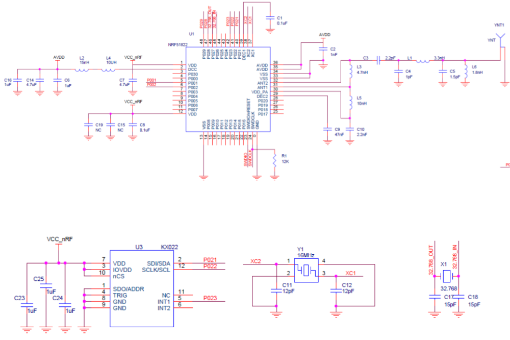
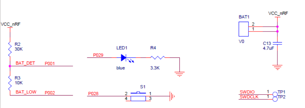
    My breakout board consists of Ebyte module and a couple of buttons. Battery is CR2450 directly connected to the module.
    Do I need DC-DC?


  • Hero Member

    @toyman With DC-DC, it uses roughly half the current during Tx and Rx. Seems like a no brainer to me, but you don't literally "need" to have it. I'm not aware of any downsides to it.


  • @neverdie thx. What is needed hardware-wise? Two inductors between dc and dec4? Like in your breakout board?


  • Hero Member

    @toyman Correct. You can review the schematic for this project: https://www.openhardware.io/view/472/Ebyte-nRF52832-Prototyping-Board


  • Hero Member

    I guess this is why I cant get LPCOMP to work on the device.

    Eight input options (AIN0 to AIN7)
    

    I would have to use the analog inputs because pin 28 is just a general purpose I/O pin.

    0_1521609771691_nrf51822-beacon-schematic.png

    0_1521609830464_nrf51822-beacon-schematic2.png


  • ebyte module is currently on sale at roughly $2.5
    Total bargain!


  • Hardware Contributor

    @korttoma using MySensors NRF5 boards you should be able to assign one AINx pin to physical pin 28.
    The index you need to put in the code is the AIN index not the pin number.


  • Hero Member

    @nca78 sorry but I cannot figure out how to do this. Should I do it in the MyBoardNRF5.cpp, MyBoardNRF5.h or in the sketch?


  • Hardware Contributor

    @korttoma sorry I said stupid things as I'm a beginner too, you can't reassign analog inputs and LPCOMP to different pins on NRF5 chips.


  • Hero Member

    @nca78 it is ok, I think I will have to set up a test system with a different device with witch I can measure current consumption, attach serial logging and then try to fiddle with the code. I'm flying in the dark with this bluetooth beacon device since I cannot access any pins.


  • @neverdie thx. Why don't you have a capacitor between DEC4 to GND? I can see only 2 inductors, while Nordic power guidelines prescribe an LC filter between DCC and DEC, ie inductors and a capacitor. nrf52dk also has it.


  • Hero Member

    @toyman I guess I made an error then. Thanks for pointing that out. In general, I haven't gotten much feedback on the PCB's that I've posted, so any feedback is always appreciated. 🙂


  • @neverdie Question is, did the DC/DC still work without the cap?


  • Hero Member

    @omemanti said in nRF5 Bluetooth action!:

    @neverdie Question is, did the DC/DC still work without the cap?

    I believe it did. If you look at: https://www.openhardware.io/view/471/Ebyte-nRF52832-Small-Breakout-Board
    which has the inductors soldered on, I believe that is the one that I tested. Enough time has passed though that I can't be 100% sure now. I made a number of different variations, and I didn't post all of them.


  • @neverdie said in nRF5 Bluetooth action!:

    nough time has passed though that I can't be 100% sure now. I made a number of different variations, and I didn't post all of them

    I used your schematic for a PCB I ordered yesterday :), did saw the post about the cap until it was too late 😞
    part of the game!

    Edit: according to your post https://forum.mysensors.org/topic/6961/nrf5-bluetooth-action/797 it did work


  • Hardware Contributor

    @nca78 said in nRF5 Bluetooth action!:

    I will try it on my board (using a module with QFAAH0) tomorrow, if power consumption is as low as expected I'll try on the beacon board.

    @NeverDie I have tried the sketch nearly unchanged (only changed to lines because I use pin P0.01 so AIN2) and my current consumption is a bit over 30uA, do you have any idea of what I should check ? (I tried with both versions 0.1 and 0.3 of MySensors NRF5 boards).
    At the moment my board only has a led and a DRV5032FB (<<1uA) in addition to the nrf51 module.


  • Hero Member

    @nca78 said in nRF5 Bluetooth action!:

    do you have any idea of what I should check ?

    Have you tried disabling serial?


  • Hardware Contributor

    @neverdie said in nRF5 Bluetooth action!:

    Have you tried disabling serial?

    Your code does it.


  • Hero Member

    Unsure then.


  • Hardware Contributor

    @nca78 said in nRF5 Bluetooth action!:

    @NeverDie I have tried the sketch nearly unchanged (only changed to lines because I use pin P0.01 so AIN2) and my current consumption is a bit over 30uA, do you have any idea of what I should check ? (I tried with both versions 0.1 and 0.3 of MySensors NRF5 boards).
    At the moment my board only has a led and a DRV5032FB (<<1uA) in addition to the nrf51 module.

    Ok, case closed, it was just because the SWD pins were still connected to my NRF52 DK. When I just connect VCC and GND it's down to something a bit below 5uA. I'm using a multimeter and DK is at 2.8V so real consumption will be a bit higher. But it should give me a battery life around 1year for my bedroom doors, so I'll just use my nrf51 modules for that and move to the more interesting nrf52.


  • Hero Member

    @nca78 would you mind sharing your sketch files for your door sensors?
    As I'm not a programmer and not so good at programing I usually rely on example code to get anything done. More examples gives me more understanding how things should be done.


  • Hardware Contributor

    @korttoma sure I will when I make them next week, I just tested with LFCOMP script from neverdie at the moment.


  • Mod

    @neverdie said in nRF5 Bluetooth action!:

    @toyman I guess I made an error then. Thanks for pointing that out.

    I actually think you were correct in your design, @NeverDie 😉

    A while ago part of the e73-2g4m04s schematic was posted on this forum:

    0_1521921760777_50a5af75-12b9-4d4e-b33b-b6a9645d88ae-image.png

    Clearly the inductors to use the DC/DC converter are not connected to DCC. There is however a capacitor C17 from DEC4 to GND.

    The Nordic reference schematic shows the missing L2 and L3, but capacitor C10 is actually present in the e73-2g4m04s (the mentioned C17, albeit only 100nF instead of 1.0uF in the reference):

    0_1521921849048_cdb5eb86-ea5e-4392-b3a7-2e3d4c4a92f0-image.png

    Therefore I think your breakout is correct, as only the inductors between DCC and DEC4 need to be added to match the reference schematic 👍

    0_1521922345076_889e8f1b-b94f-4c8c-aa8b-2c0d341fae1c-image.png


  • Hero Member


  • Hardware Contributor

    @korttoma said in nRF5 Bluetooth action!:

    @Mika what is your experience regarding battery consumption on these?

    LINK

    I put together a sketch witch seems to work fine but one CR2032 just lasts a couple of days.
    I noticed that the chip sais:
    N51822
    QFABC0
    1646UU

    QFAB translates to 16kB RAM, 128kB flash and I can not even select this option in the arduino IDE. Can this be the problem?

    @d00616 refer to his document for some high current consumption issue but I'm not sure what to do with the info.

    Is there something wrong with my sketch or is there just an old crappy chip on the device??

    So I tried your code with a more recent version of the chip and I have a power consumption around 1mA.
    This is not surprising because in fact issue 39 seems to not be completely fixed, if I believe this link:
    https://devzone.nordicsemi.com/f/nordic-q-a/577/current-consumption-when-using-rtc-ppi-and-gpiote#post-id-18533

    "The third revision hardware of the nRF51 has a solution for the GPIOTE OUT tasks, which has very low current consumption (<1uA). The third revision nRF51 hardware will be released in a few days. The third revision hardware still does not have a solution for the GPIOTE IN events, they still consume high current, so for low current applications, use the GPIOTE PORT event instead or the app_button libary."

    From what I see it was never fixed.


  • Mod


  • Hero Member

    @gohan Gee, I don't know. Can you really afford $2.55? 😉


  • Mod

    I don't know if it is a good one and I already have a bunch of stuff I bought still in the drawer 😅


  • Hero Member

    @gohan For the price, it's good. I like Fanstel's better, but they have fewer exposed pins and cost more.


  • Hero Member

    @nca78 said in nRF5 Bluetooth action!:

    use the GPIOTE PORT event instead or the app_button libary.

    Thanks again for pointing out a possible solution but again I do not know how. I will just have to be patient and wait for someone to post an example of how to use one of the methods you mentioned.


  • I have started to test a NRF51822

    and I can upload to it with Arduino IDE but I want to use vim + platformio. And I think i'm quite close 🙂

    When I ran platformio upload --target upload

    GNU MCU Eclipse 64-bits Open On-Chip Debugger 0.10.0+dev-00392-gbe9ef0b0 (2018-01-12-14:56)
    Licensed under GNU GPL v2
    For bug reports, read
    http://openocd.org/doc/doxygen/bugs.html
    0x4000
    Info : The selected transport took over low-level target control. The results might differ compared to plain JTAG/SWD
    adapter speed: 1000 kHz
    Info : Unable to match requested speed 1000 kHz, using 950 kHz
    Info : Unable to match requested speed 1000 kHz, using 950 kHz
    Info : clock speed 950 kHz
    Info : STLINK v2 JTAG v17 API v2 SWIM v4 VID 0x0483 PID 0x3748
    Info : using stlink api v2
    Info : Target voltage: 3.225841
    Info : nrf51.cpu: hardware has 4 breakpoints, 2 watchpoints
    Info : Listening on port 3333 for gdb connections
    target halted due to debug-request, current mode: Thread
    xPSR: 0xc1000000 pc: 0x000021a4 msp: 0x20004000
    ** Programming Started **
    auto erase enabled
    Warn : Unknown device (HWID 0x000000d1)
    Warn : using fast async flash loader. This is currently supported
    Warn : only with ST-Link and CMSIS-DAP. If you have issues, add
    Warn : "set WORKAREASIZE 0" before sourcing nrf51.cfg/nrf52.cfg to disable it
    target halted due to breakpoint, current mode: Thread
    xPSR: 0x61000000 pc: 0x2000001e msp: 0x20004000
    wrote 33792 bytes from file .pioenvs/nrf51_dk/firmware.hex in 1.594509s (20.696 KiB/s)
    ** Programming Finished **
    ** Verify Started **
    target halted due to breakpoint, current mode: Thread
    xPSR: 0x61000000 pc: 0x2000002e msp: 0x20004000
    verified 32960 bytes in 0.236646s (136.015 KiB/s)
    ** Verified OK **
    ** Resetting Target **
    shutdown command invoked
    

    and the output in Arduino IDE looks like:

    Open On-Chip Debugger 0.10.0-dev-00254-g696fc0a (2016-04-09-12:07)
    Licensed under GNU GPL v2
    For bug reports, read
    	http://openocd.org/doc/doxygen/bugs.html
    debug_level: 0
    0x4000
    adapter speed: 1000 kHz
    nrf51.cpu: target state: halted
    target halted due to debug-request, current mode: Thread 
    xPSR: 0xc1000000 pc: 0x0000251c msp: 0x20004000
    ** Programming Started **
    auto erase enabled
    nrf51.cpu: target state: halted
    target halted due to breakpoint, current mode: Thread 
    xPSR: 0x61000000 pc: 0x2000001e msp: 0x20004000
    wrote 31744 bytes from file /tmp/arduino_build_390477/Si7021_TemperatureNode_v007_voltage__version_7_board_.ino.hex in 1.500105s (20.665 KiB/s)
    ** Programming Finished **
    ** Verify Started **
    nrf51.cpu: target state: halted
    target halted due to breakpoint, current mode: Thread 
    xPSR: 0x61000000 pc: 0x2000002e msp: 0x20004000
    verified 31580 bytes in 0.234860s (131.312 KiB/s)
    ** Verified OK **
    ** Resetting Target **
    shutdown command invoked
    

    and my platfromio.ini looks like:

    [env:nrf51_dk]
    platform = nordicnrf51
    framework = arduino
    board = nrf51_dk
    upload_protocol = stlink 
    

    Should I modify the nrf51_dk.cfg or can anyone see whats the problem is?


  • Mod

    What interface do you guys suggest for programming the nrf52832?


  • Hardware Contributor

    @korttoma said in nRF5 Bluetooth action!:

    @nca78 said in nRF5 Bluetooth action!:

    use the GPIOTE PORT event instead or the app_button libary.

    Thanks again for pointing out a possible solution but again I do not know how. I will just have to be patient and wait for someone to post an example of how to use one of the methods you mentioned.

    I'm trying to implement it right now, not really useful for me as I will only have one beacon board for which I will need it, but it's a good occasion to learn. I'll post my results here, but probably next week as I'll have short holidays 🙂


  • Hero Member

    @nca78 👍 no hurry 😉


  • @gohan you mean programmer? Nothing beats DK with jlink.
    Other options: jlink EDU, DIY BlackMagicProbe or STLink


  • Mod

    ok, I bought 2 of the nrf52 at half the price, now what would be the cheap solution among the programmers? Jlink is on the pricy side.


  • Hardware Contributor

    @gohan said in nRF5 Bluetooth action!:

    ok, I bought 2 of the nrf52 at half the price, now what would be the cheap solution among the programmers? Jlink is on the pricy side.

    Cheap jlink clones with 4 wires from AliExpress/Ebay seem to work. So does the ST-Link v2 which is probably the cheapest option.


  • Mod

    I got kind of lost with all those jlink clones with so many different versions. The ST-Link V2 I found it on digikey and similar sites for around 18/19€, is it the right one?


  • @gohan I use both the ST-LinkV2 (2 dollars from eBay) and the NRF52832-DK both work like a charm.


  • @gohan LOL, i need to stop buying these things, got 12 just waiting to be used.. but at this price, its almost impossible to not buy them 🙂


  • @gohan said in nRF5 Bluetooth action!:

    The ST-Link V2 I found it on digikey and similar sites for around 18/19€, is it the right one?

    Don't do that. Either buy $2 clones or invest into DK or:
    https://www.adafruit.com/product/3571


  • Mod


  • @gohan sure, I bought some of those. Works great. One crashed so now I bought a couple, just to be sure.. 🙂


  • Hardware Contributor

    @nca78 said in nRF5 Bluetooth action!:

    So I tried your code with a more recent version of the chip and I have a power consumption around 1mA.
    This is not surprising because in fact issue 39 seems to not be completely fixed, if I believe this link:
    https://devzone.nordicsemi.com/f/nordic-q-a/577/current-consumption-when-using-rtc-ppi-and-gpiote#post-id-18533

    "The third revision hardware of the nRF51 has a solution for the GPIOTE OUT tasks, which has very low current consumption (<1uA). The third revision nRF51 hardware will be released in a few days. The third revision hardware still does not have a solution for the GPIOTE IN events, they still consume high current, so for low current applications, use the GPIOTE PORT event instead or the app_button libary."

    From what I see it was never fixed.

    Took time but after failure trying to make a version by myself I decided to include app_gpiote library from SDK in my script and it works, it's using around 1uA more than LPCOMP (I measure 5.5 uA with my multimeter) but it can use any pin and in theory any number of pins without increasing power consumption.
    The behavior is similar to pin change interrupt on ATMega328, you have one interrupt for all the pins you are watching, so you have to check which pin generated the interrupt but app_gpiote is preparing the work for you.
    I have this consumption with a similar script than @Neverdie for LPCOMP: using MySensors with MY_CORE_ONLY, preparing the interrupt then calling the sleep(ms) function from MySensors library, and it works as expected changing status of led immediately when I change status of pin, and waking up at the end of the interval if I don't.
    I'll do more tests tomorrow including a full MySensors script, and post the info here. It needs a bunch of files from SDK and adding a (weak) attribute to GPIOTE_IRQHandler() in sandeepmistry's code so it can be overridden in the script.


  • Mod

    @omemanti said in nRF5 Bluetooth action!:

    I bought some of those. Works great

    Do you use them with windows?
    I tried to get them to program an nrf52832, but openocd in Arduino ide under windows doesn't detect them...
    Both stlinks work in Linux.


  • Mod

    @yveaux I have used a ST-Link v2 (clone) on Windows 7, didn't run into any problems.


  • Mod

    @mfalkvidd from the arduino ide? Did you follow any guide or remember specific settings?


  • Mod

    @yveaux yes from the Arduino IDE. I just followed this guide.


  • Mod

    I did follow https://github.com/sandeepmistry/arduino-BLEPeripheral as well (for a non-MySensors use case). Not sure which one I did first.


  • Mod

    @mfalkvidd hmmm... No specific mention of any st-link stuff to configure. Must be me then 😱
    I just wanted to try some ST-links I ordered.
    Ah well, I'll give it another try and otherwise go back to my j-link, which works flawlessly.

    Thanks anyway!


  • @yveaux jup, both work on Windows . I had to install the right drivers using zadig.

    I only use the Arduino IDE for uploading, just select the st-link and it works.


  • Mod

    @omemanti ok, thanks for the feedback. I'll give that a try then 👍


  • Mod

    @omemanti yup, installed WinUSB driver with Zadig and worked instantly! Thanks again!


  • Mod

    @yveaux I have messed with some SDR dongles and might have installed WinUSB with Zadig earlier to get the SDR to work.


  • Mod

    @mfalkvidd yeah, now you tell me 😘


  • Hardware Contributor

    So I made a version of script with MySensors library, it's not a final version and needs some cleaning and improvements but it seems to work well (I didn't test so much yet :)) and shows basic usage. Comments should be enough to understand what to change to adapt to your board. Current script is for my board:

    • BUTTON_1 on pin 1, it's a hall sensor for door so no pullup and sensing on up=>down and down=>up changes
    • BUTTON_2 on pin 3, push button with pullup and debouncing, sensing only on up=>down when button is pressed. At the moment it just makes some light blinking to show it's detected.
    • led on pin 2.

    I join the main script file and the MyBoardNRF5 files, for using with MyBoardNRF5 nrf51822. Files to include are described in the main script file, but don't forget to add a weak attribute in the WInterrupt.c file before the GPIOTE_IRQHandler so it can be overridden.

    __attribute__ ((weak))
    void GPIOTE_IRQHandler()
    

    On my Windows PC this file is in C:\Users[your user name]\AppData\Local\Arduino15\packages\sandeepmistry\hardware\nRF5\0.5.1\cores\nRF5

    Main script file:

    // Include app_gpiote and related files from NRF5 SDK 12
    extern "C" {
    #include "app_gpiote.h"
    #include "nrf_gpio.h"
    #include "app_error.h"
    }
    
    // Files to include from SDK:
    // app_error_weak.h + .c
    // app_gpiote.h + .c
    // app_util.h
    // nordic_common.h
    // nrf_error.h
    // nrf_gpio.h
    // sdk_errors.h
    // app_error.h + .c
    //   for this last one (c file) I decided to stop the endless list of includes so I commented the following includes:
    //   #include "sdk_errors.h", #include "nrf_log.h", #include "nrf_log_ctrl.h"  lines
    
    #include <nrf.h>
    
    #define IS_NRF51  //true if the target is an nRF51.  If an nRF52, then comment this line out!
    #define APP_GPIOTE_MAX_USERS 1  // max users for app_gpiote, we only use one
    #define MY_RADIO_NRF5_ESB
    #define MY_NODE_ID 60   // To avoid getting a new ID at each flashing of the sensors...
    
    #include <MySensors.h>
    
    
    // variables for app_gpiote calls
    uint32_t err_code;
    static app_gpiote_user_id_t m_gpiote_user_id;
    uint32_t PIN_BUTTON1_MASK; // Mask for PIN_BUTTON1 input
    uint32_t PIN_BUTTON2_MASK; // Mask for PIN_BUTTON2 input
    
    // defines variables for MySensors
    #define SN "22Board Door Basic"
    #define SV "0.2"
    // Sensor messages
    #define CHILD_ID_DOOR 1
    MyMessage doorMsg(CHILD_ID_DOOR, V_TRIPPED);
    bool last_sent_value;
    bool door_status;
    long last_button2_event = 0;
    
    // Cause of interrupt
    volatile byte interrupt_cause = 0;
    
    
    // Settings to avoid killing coin cell in case of connection problem
    #define MY_TRANSPORT_WAIT_READY_MS  10000
    #define MY_SLEEP_TRANSPORT_RECONNECT_TIMEOUT_MS 5000
    
    // Battery settings
    #define BATTERY_ALERT_LEVEL 30  // (%) Will triple blink after sending data if battery is equal or below this level
    // Parameters for VCC measurement
    #define BATTERY_VCC_MIN  2400  // Minimum expected Vcc level, in milliVolts. 
    #define BATTERY_VCC_MAX  2900  // Maximum expected Vcc level, in milliVolts.
    // This a a coefficient to fix the imprecision of measurement of the battery voltage
    #define BATTERY_COEF 1000.0f  // (reported voltage / voltage) * 1000
    uint16_t currentBatteryPercent;
    uint16_t lastBatteryPercent = -1;
    // Enables/disables sleeps between sendings to optimize for CR2032 or similar coin cell
    #define USE_COIN_CELL
    
    
    // Called before initialization of the library
    void before() {
      hwPinMode(LED_BUILTIN, OUTPUT_D0H1);
      blinkityBlink(2, 3);
    }
    
    // Setup node
    void setup(void) {
    
      //Configure button pins as inputs
      nrf_gpio_cfg_input(PIN_BUTTON1, NRF_GPIO_PIN_NOPULL);
      nrf_gpio_cfg_input(PIN_BUTTON2, NRF_GPIO_PIN_PULLUP);
      APP_GPIOTE_INIT(APP_GPIOTE_MAX_USERS);               //Only initialize once. Increase value of APP_GPIOTE_MAX_USERS if needed
    
      // Initialize value of pin (for DRV5032 hall sensor HIGH = no magnet nearby = door opened);
      door_status = digitalRead(PIN_BUTTON1);
      last_sent_value = !door_status; // so we always send value in first loop
    
      // Registers user and pins we are "watching"
      //   gpiote_event_handler is handler called by interrupt, see method below
      PIN_BUTTON1_MASK = 1 << PIN_BUTTON1; // Set mask, will be used for registration and interrupt handler
      PIN_BUTTON2_MASK = 1 << PIN_BUTTON2; // Set mask, will be used for registration and interrupt handler
      //  app_gpiote_user_register(p_user_id, pins_low_to_high_mask, pins_high_to_low_mask, event_handler)
      //  to have no trigger for high=>low or low=>high change on your button, pass 0 instead
      //  here I check PIN_BUTTON1 on both low=>high and high=>low changes and PIN_BUTTON2 only on high=>low change when someone presses the button
      err_code = app_gpiote_user_register(&m_gpiote_user_id, PIN_BUTTON1_MASK, PIN_BUTTON1_MASK | PIN_BUTTON2_MASK, gpiote_event_handler);
      APP_ERROR_CHECK(err_code);  // will reset if user registration fails
    
      // Enable SENSE and interrupt
      err_code = app_gpiote_user_enable(m_gpiote_user_id);
      APP_ERROR_CHECK(err_code);  // will reset if SENSE enabling fails
    
      // initialize last event for button2 debounce
      last_button2_event = millis();
    }
    
    void presentation()  {
      sendSketchInfo(SN, SV);
      present(CHILD_ID_DOOR, S_DOOR);
    }
    
    // Sleep between sendings to preserve coin cell
    //  if not using button cell just make sure the #define USE_COIN_CELL is commented at the beginning of the sketch and it will do nothing
    void sleepForCoinCell() {
    #ifdef USE_COIN_CELL
      sleep(400);
    #endif
    }
    
    // main loop
    void loop(void)
    {
      // for sending battery level at first run
      if (lastBatteryPercent < 0) {
        sendBatteryStatus();
        sleepForCoinCell();
      }
    
      if (interrupt_cause == PIN_BUTTON1) {
        // if door status changed, we send door message
        if (door_status != last_sent_value) {
          sendDoorStatus();
        }
      }
      else if (interrupt_cause == PIN_BUTTON2) {
        if (millis() < last_button2_event || (millis() - last_button2_event > 100)) {
          last_button2_event = millis();
          blinkityBlink(2, 3); // not so useful, just for testing :)
        }
      }
      else {  // end of sleeping period, we send battery level
        sendBatteryStatus();
      }
    
      // Low battery warning or confirm status of door
      if (lastBatteryPercent < BATTERY_ALERT_LEVEL) {
        blinkityBlink(3, 1);
      }
      else {
        blinkityBlink((last_sent_value == true ? 2 : 1), 1);
      }
    
      // Go to sleep
      mySleepPrepare();
      interrupt_cause = 0; // reset interrupt cause
      sleep(300000);
    }
    
    void sendDoorStatus() {
      send(doorMsg.set(door_status));
      last_sent_value = door_status;
    }
    
    #define CHILD_ID_VOLT 254
    MyMessage voltMsg(CHILD_ID_VOLT, V_VOLTAGE);
    void sendBatteryStatus() {
      uint16_t batteryVoltage = hwCPUVoltage();
    
      if (batteryVoltage > BATTERY_VCC_MAX) {
        currentBatteryPercent = 100;
      }
      else if (batteryVoltage < BATTERY_VCC_MIN) {
        currentBatteryPercent = 0;
      }
      else {
        currentBatteryPercent = (100 * (batteryVoltage - BATTERY_VCC_MIN)) / (BATTERY_VCC_MAX - BATTERY_VCC_MIN);
      }
      if (currentBatteryPercent != lastBatteryPercent) {
        sendBatteryLevel(currentBatteryPercent);
        lastBatteryPercent = currentBatteryPercent;
      }
    }
    
    // "Interrupt handler"
    //  not real handler, but call inside handler to
    void gpiote_event_handler(uint32_t event_pins_low_to_high, uint32_t event_pins_high_to_low)
    {
      MY_HW_RTC->CC[0] = (MY_HW_RTC->COUNTER + 2); // Taken from d0016 example code, ends the sleep delay
      if ((PIN_BUTTON1_MASK & event_pins_low_to_high) || (PIN_BUTTON1_MASK & event_pins_high_to_low)) {
        interrupt_cause = PIN_BUTTON1;
        door_status = !door_status;
      }
      else if ((PIN_BUTTON2_MASK & event_pins_low_to_high) || (PIN_BUTTON2_MASK & event_pins_high_to_low)) {
        interrupt_cause = PIN_BUTTON2;
      }
    }


    /**
       Utility functions for NRF51/52, from nerverdie's code here
       https://forum.mysensors.org/topic/6961/nrf5-bluetooth-action/1307
    */
    
    
    void disableNfc() {  //only applied to nRF52
    
    #ifndef IS_NRF51
      //Make pins 9 and 10 usable as GPIO pins.
      NRF_NFCT->TASKS_DISABLE = 1; //disable NFC
      NRF_NVMC->CONFIG = 1; // Write enable the UICR
      NRF_UICR->NFCPINS = 0; //Make pins 9 and 10 usable as GPIO pins.
      NRF_NVMC->CONFIG = 0; // Put the UICR back into read-only mode.
    #endif
    }
    
    void turnOffRadio() {
      NRF_RADIO->TASKS_DISABLE = 1;
      while (!(NRF_RADIO->EVENTS_DISABLED)) {}  //until radio is confirmed disabled
    }
    
    void turnOffUarte0() {
    #ifndef IS_NRF51
      NRF_UARTE0->TASKS_STOPRX = 1;
      NRF_UARTE0->TASKS_STOPTX = 1;
      NRF_UARTE0->TASKS_SUSPEND = 1;
      NRF_UARTE0->ENABLE = 0; //disable UART0
      while (NRF_UARTE0->ENABLE != 0) {}; //wait until UART0 is confirmed disabled.
    #endif
    
    #ifdef IS_NRF51
      NRF_UART0->TASKS_STOPRX = 1;
      NRF_UART0->TASKS_STOPTX = 1;
      NRF_UART0->TASKS_SUSPEND = 1;
      NRF_UART0->ENABLE = 0; //disable UART0
      while (NRF_UART0->ENABLE != 0) {}; //wait until UART0 is confirmed disabled.
    #endif
    }
    
    void turnOffAdc() {
    #ifndef IS_NRF51
      if (NRF_SAADC->ENABLE) { //if enabled, then disable the SAADC
        NRF_SAADC->TASKS_STOP = 1;
        while (NRF_SAADC->EVENTS_STOPPED) {} //wait until stopping of SAADC is confirmed
        NRF_SAADC->ENABLE = 0; //disable the SAADC
        while (NRF_SAADC->ENABLE) {} //wait until the disable is confirmed
      }
    #endif
    }
    
    
    void turnOffHighFrequencyClock() {
      NRF_CLOCK->TASKS_HFCLKSTOP = 1;
      while ((NRF_CLOCK->HFCLKSTAT) & 0x0100) {}  //wait as long as HF clock is still running.
    }
    
    
    void mySleepPrepare()
    {
      turnOffHighFrequencyClock();
      turnOffRadio();
      turnOffUarte0();
    }
    
    
    void blinkityBlink(uint8_t pulses, uint8_t repetitions) {
      for (int x = 0; x < repetitions; x++) {
        // wait only in case there's been a previous blink
        if (x > 0) {
          sleep(500);
        }
        for (int i = 0; i < pulses; i++) {
          // wait only in case there's been a previous blink
          if (i > 0) {
            sleep(100);
          }
          digitalWrite(LED_BUILTIN, HIGH);
          wait(20);
          digitalWrite(LED_BUILTIN, LOW);
        }
      }
    }


    MyBoardNRF5.h

    /*
      If you don't use an nRF5 board, you can ignore this file.
      This file was part of the "My Sensors nRF5 Boards" board repository
      available at https://github.com/mysensors/ArduinoBoards If you have
      questions, please refer the documentation at
      https://github.com/mysensors/ArduinoHwNRF5 first.
      This file is compatible with ArduinoHwNRF5 >= 0.2.0
      This file allows you to change the pins of internal hardware, like the
      serial port, SPI bus or Wire bus.
      All pins referenced here are mapped via the "g_ADigitalPinMap" Array
      defined in "MyBoardNRF5.cpp" to pins of the MCU.
      
      As an example, if you have at the third position in "g_ADigitalPinMap" the
      12, then all ports referenced in Arduino with 2 are mapped to P0.12. If you
      don't change the "g_ADigitalPinMap" Array, the Arduino pins 0..31 are
      translated to P0.00..P0..31.
       
      ###########################################################################
     
      This file is compatible with ArduinoHwNRF5 > 0.1.0
      Copyright (c) 2014-2015 Arduino LLC.  All right reserved.
      Copyright (c) 2016 Sandeep Mistry. All right reserved.
      Copyright (c) 2017 Sensnology AB. All right reserved.
      This library is free software; you can redistribute it and/or
      modify it under the terms of the GNU Lesser General Public
      License as published by the Free Software Foundation; either
      version 2.1 of the License, or (at your option) any later version.
      This library is distributed in the hope that it will be useful,
      but WITHOUT ANY WARRANTY; without even the implied warranty of
      MERCHANTABILITY or FITNESS FOR A PARTICULAR PURPOSE.
      See the GNU Lesser General Public License for more details.
      You should have received a copy of the GNU Lesser General Public
      License along with this library; if not, write to the Free Software
      Foundation, Inc., 51 Franklin St, Fifth Floor, Boston, MA  02110-1301  USA
    */
    
    #ifndef _MYBOARDNRF5_H_
    #define _MYBOARDNRF5_H_
    
    #ifdef __cplusplus
    extern "C"
    {
    #endif // __cplusplus
    
    // Number of pins defined in PinDescription array
    #define PINS_COUNT           (32u)
    #define NUM_DIGITAL_PINS     (32u)
    #define NUM_ANALOG_INPUTS    (8u)
    #define NUM_ANALOG_OUTPUTS   (8u)
    
    /* 
     *  LEDs
     *  
     *  This is optional
     *  
     *  With My Sensors, you can use
     *  hwPinMode() instead of pinMode()
     *  hwPinMode() allows to use advanced modes like OUTPUT_H0H1 to drive LEDs.
     *  https://github.com/mysensors/MySensors/blob/development/drivers/NRF5/nrf5_wiring_constants.h
     *
     */
    #define PIN_LED1                (2)
    // #define PIN_LED2                (25)
    // #define PIN_LED3                (26)
    // #define PIN_LED4                (27)
    // #define PIN_LED5                (12)
    // #define PIN_LED6                (14)
    // #define PIN_LED7                (15)
    // #define PIN_LED8                (16)
    // #define USER_LED                (PIN_LED2)
    // #define RED_LED                 (PIN_LED3)
    // #define GREEN_LED               (PIN_LED4)
    // #define BLUE_LED                (PIN_LED1)
    // #define BLE_LED                 BLUE_LED
    #define LED_BUILTIN          PIN_LED1
    
    /* 
     *  Buttons
     *  
     *  This is optional
     */
    #define PIN_BUTTON1             (1)
    #define PIN_BUTTON2             (3)
    // #define PIN_BUTTON3             (5)
    // #define PIN_BUTTON4             (6)
    // #define PIN_BUTTON5             (7)
    // #define PIN_BUTTON6             (8)
    // #define PIN_BUTTON7             (9)
    // #define PIN_BUTTON8             (10)
    
    /* 
     * Analog ports
     *  
     * If you change g_APinDescription, replace PIN_AIN0 with
     * port numbers mapped by the g_APinDescription Array.
     * You can add PIN_AIN0 to the g_APinDescription Array if
     * you want provide analog ports MCU independed, you can add
     * PIN_AIN0..PIN_AIN7 to your custom g_APinDescription Array
     * defined in MyBoardNRF5.cpp
     */
     /*
    static const uint8_t A0  = ADC_A0;
    static const uint8_t A1  = ADC_A1;
    static const uint8_t A2  = ADC_A2;
    static const uint8_t A3  = ADC_A3;
    static const uint8_t A4  = ADC_A4;
    static const uint8_t A5  = ADC_A5;
    static const uint8_t A6  = ADC_A6;
    static const uint8_t A7  = ADC_A7;
    */
    /*
     * Serial interfaces
     * 
     * RX and TX are required.
     * If you have no serial port, use unused pins
     * CTS and RTS are optional.
     */
    #define PIN_SERIAL_RX       (29)
    #define PIN_SERIAL_TX       (28)
    // #define PIN_SERIAL_CTS      (13)
    // #define PIN_SERIAL_RTS      (14)
    
    /*
     * SPI Interfaces
     * 
     * This is optional
     * 
     * If SPI is defined MISO, MOSI, SCK are required
     * SS is optional and can be used in your sketch.
     */
    #define SPI_INTERFACES_COUNT 0
    
    #define PIN_SPI_MISO         (6)
    #define PIN_SPI_MOSI         (3)
    #define PIN_SPI_SCK          (4)
    #define PIN_SPI_SS           (5)
    
    static const uint8_t SS   = PIN_SPI_SS;
    static const uint8_t MOSI = PIN_SPI_MOSI;
    static const uint8_t MISO = PIN_SPI_MISO;
    static const uint8_t SCK  = PIN_SPI_SCK;
    
    /*
     * Wire Interfaces
     *
     * This is optional
     */
    #define WIRE_INTERFACES_COUNT 1
    
    #define PIN_WIRE_SDA         (9u)
    #define PIN_WIRE_SCL         (10u)
    /*
    #define PIN_WIRE_SDA1        (15u)
    #define PIN_WIRE_SCL1        (16u)
    */
    static const uint8_t SDA = PIN_WIRE_SDA;
    static const uint8_t SCL = PIN_WIRE_SCL;
    
    #ifdef __cplusplus
    }
    #endif
    
    #endif
    

    MyBoardNRF5.cpp

    /*
      If you don't use an nRF5 board, you can ignore this file.
      
      This file was part of the "My Sensors nRF5 Boards" board repository
      available at https://github.com/mysensors/ArduinoBoards If you have
      questions, please refer the documentation at
      https://github.com/mysensors/ArduinoHwNRF5 first.
      
      This file is compatible with ArduinoHwNRF5 >= 0.2.0
      This file allows you to change the relation between pins referenced in
      the Arduino IDE (0..31) and pins of the nRF5 MCU (P0.00..P0.31).
      
      If you can live with addressing the GPIO pins by using the Arduino pins
      0..31 instead of a custom mapping, don't change this file. If you have
      a lot of Arduino code with fixed pin numbers and you need to map these
      pins to specific pins of the nRF5 MCU; you need to change this file.
      
      If you fill the "g_APinDescription" Array with numbers between 0..31,
      the Arduino pins 0..31 are assigned to pins P0.00..P0.31 of the MCU.
      
      As an example, if you need to change the pin mapping for Arduino pin 5
      to P0.12 of the MCU, you have to write the 12 after PORT0 into the sixth
      position in the  "g_APinDescription" Array.
       
      The extended attributes only affects the nRF5 variants provided with
      official Arduino boards. The arduino-nrf5 variant ignores the extended
      attributes.
        
      The pin mapping effects commands like "pinMode()", "digitalWrite()",
      "analogRead()" and "analogWrite()".
      
      If you change the pin mapping, you have to modify the pins in
      "MyBoardNRF5.h". Especially the analog pin mapping must be replaced with
      your pin numbers by replacing PIN_AIN0..7 with a number of your mapping
      array. You can use the constants PIN_AIN0..7 in the "g_APinDescription"
      Array if you want to reference analog ports MCU independent. You cannot
      use the pins P0.00 and P0.01 for GPIO, when the 32kHz crystal is connected.
      
      ###########################################################################
      Copyright (c) 2014-2015 Arduino LLC.  All right reserved.
      Copyright (c) 2016 Arduino Srl.  All right reserved.
      Copyright (c) 2017 Sensnology AB. All right reserved.
      This library is free software; you can redistribute it and/or
      modify it under the terms of the GNU Lesser General Public
      License as published by the Free Software Foundation; either
      version 2.1 of the License, or (at your option) any later version.
      This library is distributed in the hope that it will be useful,
      but WITHOUT ANY WARRANTY; without even the implied warranty of
      MERCHANTABILITY or FITNESS FOR A PARTICULAR PURPOSE.
      See the GNU Lesser General Public License for more details.
      You should have received a copy of the GNU Lesser General Public
      License along with this library; if not, write to the Free Software
      Foundation, Inc., 51 Franklin St, Fifth Floor, Boston, MA  02110-1301  USA
    */


    #ifdef MYBOARDNRF5
    #include <variant.h>
    
    /*
     * Pins descriptions. Attributes are ignored by arduino-nrf5 variant. 
     * Definition taken from Arduino Primo Core with ordered ports
     */
    const PinDescription g_APinDescription[]=
    {
      { PORT0,  0, PIO_DIGITAL, (PIN_ATTR_DIGITAL|PIN_ATTR_PWM), No_ADC_Channel, PWM0, NOT_ON_TIMER},  // AREF0 ADC/LPCOMP reference input 0
      { PORT0,  1, PIO_DIGITAL, (PIN_ATTR_DIGITAL|PIN_ATTR_PWM), ADC_A2, PWM1, NOT_ON_TIMER},
      { PORT0,  2, PIO_DIGITAL, (PIN_ATTR_DIGITAL|PIN_ATTR_PWM), ADC_A3, PWM2, NOT_ON_TIMER},
      { PORT0,  3, PIO_DIGITAL, (PIN_ATTR_DIGITAL|PIN_ATTR_PWM), ADC_A4, PWM3, NOT_ON_TIMER},
      { PORT0,  4, PIO_DIGITAL, (PIN_ATTR_DIGITAL|PIN_ATTR_PWM), ADC_A5, PWM4, NOT_ON_TIMER},
      { PORT0,  5, PIO_DIGITAL, (PIN_ATTR_DIGITAL|PIN_ATTR_PWM), ADC_A6, PWM5, NOT_ON_TIMER},
      { PORT0,  6, PIO_DIGITAL, (PIN_ATTR_DIGITAL|PIN_ATTR_PWM), ADC_A7, PWM6, NOT_ON_TIMER}, // AREF1 ADC/LPCOMP reference input 1
      { PORT0,  7, PIO_DIGITAL, (PIN_ATTR_DIGITAL|PIN_ATTR_PWM), No_ADC_Channel, PWM7, NOT_ON_TIMER},
      { PORT0,  8, PIO_DIGITAL, (PIN_ATTR_DIGITAL|PIN_ATTR_PWM), No_ADC_Channel, PWM8, NOT_ON_TIMER},
      { PORT0,  9, PIO_DIGITAL, (PIN_ATTR_DIGITAL|PIN_ATTR_PWM), No_ADC_Channel, PWM9, NOT_ON_TIMER}, 
      { PORT0, 10, PIO_DIGITAL, (PIN_ATTR_DIGITAL|PIN_ATTR_PWM), No_ADC_Channel, PWM10, NOT_ON_TIMER},
      { PORT0, 11, PIO_DIGITAL, (PIN_ATTR_DIGITAL|PIN_ATTR_PWM), No_ADC_Channel, PWM11, NOT_ON_TIMER},
      { PORT0, 12, PIO_DIGITAL, (PIN_ATTR_DIGITAL|PIN_ATTR_PWM), No_ADC_Channel, NOT_ON_PWM, NOT_ON_TIMER},
      { PORT0, 13, PIO_DIGITAL, (PIN_ATTR_DIGITAL|PIN_ATTR_PWM), No_ADC_Channel, NOT_ON_PWM, NOT_ON_TIMER},
      { PORT0, 14, PIO_DIGITAL, (PIN_ATTR_DIGITAL|PIN_ATTR_PWM), No_ADC_Channel, NOT_ON_PWM, NOT_ON_TIMER},
      { PORT0, 15, PIO_DIGITAL, (PIN_ATTR_DIGITAL|PIN_ATTR_PWM), No_ADC_Channel, NOT_ON_PWM, NOT_ON_TIMER},
      { PORT0, 16, PIO_DIGITAL, (PIN_ATTR_DIGITAL|PIN_ATTR_PWM), No_ADC_Channel, NOT_ON_PWM, NOT_ON_TIMER},
      { PORT0, 17, PIO_DIGITAL, (PIN_ATTR_DIGITAL|PIN_ATTR_PWM), No_ADC_Channel, NOT_ON_PWM, NOT_ON_TIMER},
      { PORT0, 18, PIO_DIGITAL, (PIN_ATTR_DIGITAL|PIN_ATTR_PWM), No_ADC_Channel, NOT_ON_PWM, NOT_ON_TIMER},
      { PORT0, 19, PIO_DIGITAL, (PIN_ATTR_DIGITAL|PIN_ATTR_PWM), No_ADC_Channel, NOT_ON_PWM, NOT_ON_TIMER},
      { PORT0, 20, PIO_DIGITAL, (PIN_ATTR_DIGITAL|PIN_ATTR_PWM), No_ADC_Channel, NOT_ON_PWM, NOT_ON_TIMER},
      { PORT0, 21, PIO_DIGITAL, (PIN_ATTR_DIGITAL|PIN_ATTR_PWM), No_ADC_Channel, NOT_ON_PWM, NOT_ON_TIMER},
      { PORT0, 22, PIO_DIGITAL, (PIN_ATTR_DIGITAL|PIN_ATTR_PWM), No_ADC_Channel, NOT_ON_PWM, NOT_ON_TIMER},
      { PORT0, 23, PIO_DIGITAL, (PIN_ATTR_DIGITAL|PIN_ATTR_PWM), No_ADC_Channel, NOT_ON_PWM, NOT_ON_TIMER},
      { PORT0, 24, PIO_DIGITAL, (PIN_ATTR_DIGITAL|PIN_ATTR_PWM), No_ADC_Channel, NOT_ON_PWM, NOT_ON_TIMER},
      { PORT0, 25, PIO_DIGITAL, (PIN_ATTR_DIGITAL|PIN_ATTR_PWM), No_ADC_Channel, NOT_ON_PWM, NOT_ON_TIMER},
      { PORT0, 26, PIO_DIGITAL, (PIN_ATTR_DIGITAL|PIN_ATTR_PWM), ADC_A0, NOT_ON_PWM, NOT_ON_TIMER},
      { PORT0, 27, PIO_DIGITAL, (PIN_ATTR_DIGITAL|PIN_ATTR_PWM), ADC_A1, NOT_ON_PWM, NOT_ON_TIMER},
      { PORT0, 28, PIO_DIGITAL, (PIN_ATTR_DIGITAL|PIN_ATTR_PWM), No_ADC_Channel, NOT_ON_PWM, NOT_ON_TIMER},
      { PORT0, 29, PIO_DIGITAL, (PIN_ATTR_DIGITAL|PIN_ATTR_PWM), No_ADC_Channel, NOT_ON_PWM, NOT_ON_TIMER}
    };
    
    // Don't remove this line
    #include <compat_pin_mapping.h>
    
    #endif
    

  • Plugin Developer

    I'm struggling to get my EByte NRF52 to work. I'm on a mac, so it should be easy..

    I installed the two boards in the Arduino IDE.
    https://github.com/sandeepmistry/arduino-nRF5
    https://github.com/mysensors/ArduinoBoards

    Then I carefully soldered some wires on it, and connected it to my ST-Link V2:
    gnd ->gnd (in the corner)
    3.3v -> vcc (in the same corner)
    SWDIO -> SWDIO
    SWDCLK -> SWDCLK

    alt text

    Downloaded the example app with three files in one folder (like the post above this one)

    • Main file
    • MyBoardNRF5.h
    • MyBoardNRF5.cpp

    In Arduino I set things up:

    • Board: "MyBoardNRF5 NRF52832"
    • Reset: "don't enable"
    • Bootloader/SD: "none"
    • Low frequency clock: "RC Oscilator" (tried others too)
    • Port: none
    • Programmer: ST-Link V2

    Then I try "sketch -> upload via programmer"
    I tried to 'wipe' the chip by clicking "tools -> burn bootloader"

    I always get:

    Open On-Chip Debugger 0.10.0-dev-gdc53227 (2016-04-09-13:45)
    Licensed under GNU GPL v2
    For bug reports, read
    	http://openocd.org/doc/doxygen/bugs.html
    debug_level: 2
    0x4000
    Info : The selected transport took over low-level target control. The results might differ compared to plain JTAG/SWD
    adapter speed: 10000 kHz
    Info : Unable to match requested speed 10000 kHz, using 4000 kHz
    Info : Unable to match requested speed 10000 kHz, using 4000 kHz
    Info : clock speed 4000 kHz
    Info : STLINK v2 JTAG v19 API v2 SWIM v4 VID 0x0483 PID 0x3748
    Info : using stlink api v2
    Info : Target voltage: 3.242857
    Info : nrf52.cpu: hardware has 0 breakpoints, 2 watchpoints
    Error: timed out while waiting for target halted
    TARGET: nrf52.cpu - Not halted
    in procedure 'program' 
    in procedure 'reset' called at file "embedded:startup.tcl", line 478
    in procedure 'ocd_bouncer'
    
    embedded:startup.tcl:454: Error: ** Unable to reset target **
    in procedure 'program' 
    in procedure 'program_error' called at file "embedded:startup.tcl", line 479
    at file "embedded:startup.tcl", line 454
    the selected serial port at file "embedded:startup.tcl", line 454
     does not exist or your board is not connected
    

    I found loads of things online and in this thread.

    • Could it be some kind of security bit that needs to be erased?
    • I also suspect I have not connected it properly? Does the board have a power / indicator LED that should light up when its connected to power? Nothing lights up currently..
    • Does the STLink V2 not provide enough power?
    • I replaced the wires. Same problem.

Log in to reply
 

Suggested Topics

  • 8
  • 2
  • 3
  • 1
  • 1
  • 44

21
Online

11.2k
Users

11.1k
Topics

112.5k
Posts