nRF5 action!


  • Banned

    This post is deleted!


  • @scalz I'm not trying to dismiss your point, I get it. It just surprises me that you stand against "diy'ing a probe" while still being a part of DIY community which gathered around idea of making things fast and cheap. Why bother with mysensors, if we can buy all the same from Ikea, Xiaomi of Philips, or many other manufacturers, sometimes not even much pricier?
    To sum up what I'm trying to say, and finish this debate. I've spoken about my experience as nrf5 newcomer. And exactly as a newcomer I've found this way being better for me. I don't use Segger, Keil or Windows, nor I am planning to use them in future, and if I will, I would probably be able to afford buying myself a J-link.
    To get "DIY" version of BMP you need either ST-link v2 or any STM32 board, bluepill for example. And to flash one of those you obviously need another ST-link. That's all.
    BMP supports SWO which have it's own specifics compared to RTT, but basically does the same thing.


  • Hero Member


  • @neverdie that seems to be for folks who are against STM32 chips πŸ™‚


  • Hardware Contributor

    @monte
    it's not standing against diy'ing etc..really you didn't understand my point, it's just about user friendly and easily repetable getting started for MySensors nrf5 newcomers, for simply flashing their sketch.. even if a diy BMP is certainly a good probe too. and a genuine BMP is more expensive than a jlink mini. Compare both a jlink vs a blank diy probe, and with a stopwatch, you'll see which method is faster and easier for a noob..

    But ok, I won't insist anymore, if you prefer to get me wrong, really don't mind.. I should better let user with not much xp manage all alone so no debate, as this just makes me less active, see you next year 😁

    Just don't forget future newcomers will read your advices. In the meantime, we'll try to update docs for MySensors nrf5.

    Have fun with your probe


  • @scalz C'mon, would you leave the forum with just one hit? πŸ˜„
    In fact I understand your point completely. Open source has become more and more caotic. Internet is atemporal, and often people has the bad habit of not putting the complete date at the top of their "articles" that makes that search engines cannot filter and order properly.
    Everyone has a blog and writes whatever gets out him. The majority of people uses that as a remainder for themselves and... whynot getting reward. So there are zillions of howtos made anyhow. They are not written for helping people.

    If the sources and destination are always one, why there aren't the binaries available and all writeups talk about messing the computer and compiling? I think that's because nowadays people seek praise for having achieved it.

    Scalz point is about economy of time. Because time is money, even if it's spare time, and yes, a paid/proprietary probe becomes cheap, giving the documentation on the internet, today.

    Also the point of view depends in the situation of everyone and its age. Someone at the 5thies feels earlier that it's wasting time, and there comes frustration, and complaining posts, unfortunately πŸ™„
    Just buy a probe, forget about it until it gets delivered.

    @monte BTW, I was trying to program an stm32 board with a jlink. Not a Jlink. Maybe if there was a way to get an already compiled binary (to avoid all those dependencies errors) and program the jlink with a normal serial ttl...


  • @sergio-rius well, I've gotten majority of my computer knowledge and almost everything I know about programming MCU from such blog posts and articles. Some of them where better, some worse, maybe 10% were complete garbage. But anyhow I can't and won't complain. Because no person is obliged to write something that everyone will understand, and not everyone is naturally born teacher, to prepare information in suitable for wide variety of people way. But all of them were people, who thought it will be helpful to share their experience with others, to show them that this can be done, and maybe give at least hints to how to achieve it. I think there is not much use if you just follow steps, written by someone, without any thought process, or trying understand what you are doing. And thus when you try to achieve something that, won't work from the beginning and guide seems to be outdated, or not complete, you teach yourself and this is most precious in thewhole process.
    I don't think it is correct to blame those, who made a guide for that you can't replicate all the steps. Time goes, libraries an packages evolve, and in few moths fully functional guide can become obsolete if you can't make some adaptations.
    Anyway, here is more recent guide, but written with older ubuntu version in mind. You may look at it, if you want: https://buger.dread.cz/category/stm32.html


  • You know... Great power comes with a great responsibility 😊


  • Hero Member

    I happened just now to notice that ON Semiconductor has released their own (non-Nordic) version of an integrated Bluetooth + ARM Cortex + antenna with all passives:
    https://www.mouser.com/datasheet/2/308/RSL10SIP-D-1511181.pdf

    What's remarkable is that the entire thing, including the antenna and all the passives (which are built into it) is just 8mm x 6mm in size. As a result, it's very easy for them to make a very small sensor beacon:
    alt text

    "The RSL10 SIP features an onβˆ’board antenna, RSL10 radio SoC,
    and all necessary passive components in one package to help minimize
    overall system size. Already fully qualified to FCC, CE, and other
    regulatory standards; RSL10 SIP removes the need for additional
    antenna design considerations or RF certifications."

    Personally, I don't currently have the skill to solder anything that small, but maybe with the PCBA services that are becoming available.....

    I post this here merely as an illustration of what's truly possible. I can only guess, but I presume Nordic will probably (?) release something similar in the future. It would be nice not having to rely on module vendors but instead just mount the chip directly.


  • Hero Member

    By the way, maybe the Black Magic Probe can function as a kind of "universal" JTAG interface? For instance, would it work well o an ESP32 and/or anything else that relies on JTAG for debugging and/or burning firmware? Or would an ST JTAG probe work just as well?

    Is this right? I'd prefer to consolidate on a single thing rather than having a different JTAG interface device for every different kind of hardware that might need programming/debugging:

    #274 Free Inline Debugging for ESP32 and Arduino Sketches – 17:46
    β€” Andreas Spiess


  • Hardware Contributor

    @neverdie
    afaik BMP officially targets ARM mcus, whereas ESP32 is not ARM, it's Tensilica.


  • Hero Member

    @neverdie On the other hand, I bet that tiny RSL10 integrated radio+antenna package has very limited range. What I noticed from the various nRF52840 modules that I've tried is that the smaller the module, the worse the radio range. I haven't yet encountered any exceptions to that generalization.


  • @waspie just to follow up, 24hr reboot() is working perfectly. Appreciate the help.


  • @ncollins good news

    I wonder if this has anything to do with it?
    https://forum.mysensors.org/topic/10705/nrf52-watchdog-problem-myboardnrf5


  • @waspie Given that all of my interrupt nodes stopped triggering after 36 hrs (before your reboot workaround), it has to be related. It’s just weird that my nodes would continue to wake up and broadcast battery level.

    Is the LPCOMP interrupt method dependent on the wdt? Maybe resetting/restarting the wdt every 24hrs would suffice? Or maybe you have to reactivate LPCOMP every 36 hr wdt cycle?


  • Hero Member

    When are we going to see newer nRF52 modules featuring antenna diversity?

    Somewhere I still have this prototype module that I purchased a few years ago:

    alt text

    I got it working and wrote about it at the time, but I haven't seen any more up-to-date modules featuring antenna diversity since then. Definitely nothing featuring an nRF52840, for instance. What gives?


  • Hello guys. I wished I have found this forum earlier. I'm currently trying to extract/dump a firmware from nRF51. Using OpenOCD and ST-Link V2. I am facing some problems and have posted it on stackexchange and stackoverflow. Here are the posts:

    https://reverseengineering.stackexchange.com/questions/22897/blank-binwalk-and-binvis-io

    https://stackoverflow.com/questions/59710114/dumping-nrf51s-firmware

    Hopefully someone here could help me. Thanks in advance


  • Hero Member

    @Calvin-Khung a black magic probe would allow you to do that.


  • @NeverDie What is the difference with a ST-Link? I mean, I've read the features on GitHub but I don't really get the differences though πŸ˜… Sorry, as stated in both links, I'm still a noob.


  • Oh, is the command mass erase the same as dump image? If I mass erase, will the bin file appear in the bin folder?


  • @Calvin-Khung Hi Calvin, I read your comments here and on Stackoverflow/exchange. I honestly think that you dont have the right skills to do this. The exploited vulnerability in the blog is quite sofisticated. I think you have to start getting your debugger configured correctly. Your say you have an st-link v2 which lets me to belive you have a cheap chinese clone.
    This clone has not all debugging features included, as you might saw in my posts earlier. You are much better of with a Black magic probe or a J-Link.
    Have you got a halted NRF51 yet?


  • @mr_red If it's a clone then that would probably explain why it wasn't successful. I've read a thing or two about the BMP. Do you think its a good idea to convert the cheap ST-Link V2 to a BMP? Found a blog about it.

    http://blog.linuxbits.io/2016/02/15/cheap-chinese-st-link-v-2-programmer-converted-to-black-magic-probe-debugger/

    J-Link is way too expensive so I won't even bother considering it. And I don't quite get what you mean but yeah, I did halt it during the process.


  • @Calvin-Khung you can convert st-link clone into BMP. The only problem would be if there is not enough flash on the chip. If I remember correctly, BMP firmware needs more than 64kb. But you will know for sure, if you'll try.


  • @monte For sure, I'll give it a try. Thanks for helping out guys!


  • Calvin, You cam buy a Nordic Development kit for about $50 dollars or less. It has the J-Link OB device on it for swd programming and debugging.


  • Hardware Contributor

    @Jokgi said in nRF5 action!:

    Calvin, You cam buy a Nordic Development kit for about $50 dollars or less. It has the J-Link OB device on it for swd programming and debugging.

    Best solution imho, never had a problem with it programming the nrf5 modules, just drag & drop from Windows file explorer.


  • @Calvin-Khung
    Jokgi
    Jokgi about 2 hours ago

    Calvin, You can buy a Nordic Development kit for about $50 dollars or less. It has the J-Link OB device on it for SWD programming and debugging.


  • Hero Member

    I agree with Jokgi, but nonetheless for anyone interested in the Black Magic Probe alternative, here's an article on how to make a BMP from a $2 Blue Pill board:
    https://medium.com/@paramaggarwal/converting-an-stm32f103-board-to-a-black-magic-probe-c013cf2cc38c


  • i use $10 replica Jlink from aliexpress works ok with the latest firmware without an issue. i use it just to flash bootloaders to cortex m0-m4 and nrf52's but it should work for any task that a genuine jlink can do.


  • There also is an "Education" version of the Jlink for $20 if you want an official one with access to nRF Command Line Tools.


  • @Jon-Raymond Correct. It is a nice product for the price and the intended user. As Jon mentioned, you can use the command line tools as well as nRFconnect and also has direct hooks into the Segger Embedded Studio which is a fully functional IDE / compiler/ Debugger and is free when used with Nordic Semi devices.
    Plus there is no license conflict as there is when using one of these cheap overseas j-link knock offs. (Which could "break / brick" anytime doing a "official" Segger update on these clones.)


  • @orhanyor good to hear! i ordered that as well since just to try it out in hope that it would work. now that you've said that, maybe i shouldn't worry too much then.


  • @Calvin-Khung Well im actually surprised that it still works because people are reporting they might stop working after a firmware update so you might wanna hold back on that other than that it works surprisingly well. i bought another as my back up plan which im expecting it in these days. its abit different than the one i have. this one is much cheaper and looks like jlink edu mini rather than a normal j link with a black box.. i ll see if it works when i receive it, here it is.
    https://www.aliexpress.com/item/32669702891.html?spm=a2g0s.9042311.0.0.27424c4d4Fx7g9


  • i just received this little thing, tested it with atmel studio just to flash some M4 boards and it worked nicely. i wanted to update its firmware via jlink(playing with fire) but it didnt let me saying its up to date so its all ok i guess. it only has 4 pins 3v, gnd, swdio, swclk. for $2.50 in total with shipping its a steal πŸ™‚
    IMG_3313.jpg


  • @orhanyor Is it just me or does that micro usb connector look like it should be mounted upside down so it actually nests into the cutout in the board below it? Of course the pinout would be mirrored but it seems like a layout issue that they just ran with.


  • usb connector is actually nested as far as i can see but it dips 1-2 mm only. weird but it works so its all good πŸ™‚


  • This post is deleted!


  • Does anyone have any experience with the minew modules?

    https://www.aliexpress.com/item/4000111771020.html?spm=a2g0o.productlist.0.0.355350384gOEfO&algo_pvid=0304e5fd-2ee1-4b3c-8324-d7457ed54a60&algo_expid=0304e5fd-2ee1-4b3c-8324-d7457ed54a60-3&btsid=0ab50f4415945033578573060e726c&ws_ab_test=searchweb0_0,searchweb201602_,searchweb201603_

    I've been using the Fanstel BT832 series with success, but I have been looking at this one to get a few more hand-solderable GPIOs.


  • I received a few of the Minew MS50SFB modules. They appear to need unlocking similar to the E73 modules. I have tried using instructions as for E73, but no luck so far with either
    gdb
    https://forum.mysensors.org/topic/9266/guide-nrf5-nrf51-nrf52-for-beginners/54?_=1598203470928
    acts like it is working, but doesn't really unlock the module.

    or J-link
    https://forum.mysensors.org/topic/9266/guide-nrf5-nrf51-nrf52-for-beginners/33?_=1598203470928
    returns error from nrfjprob. In J-Link application can not connect


  • Hero Member

    @nagelc If you do manage to get it working, I'd be curious as to what kind of range you get out of it a compared to other modules. The antenna pattern looks a bit different.


  • Hero Member

    @nagelc It's a shot in the dark, but maybe you want to check the schematic for any differences with other modules that you've previously programmed successfully. Either it's a dud, or it must be that.


  • Hardware Contributor

    @nagelc said in nRF5 action!:

    I received a few of the Minew MS50SFB modules. They appear to need unlocking similar to the E73 modules. I have tried using instructions as for E73, but no luck so far with either
    gdb
    https://forum.mysensors.org/topic/9266/guide-nrf5-nrf51-nrf52-for-beginners/54?_=1598203470928
    acts like it is working, but doesn't really unlock the module.

    or J-link
    https://forum.mysensors.org/topic/9266/guide-nrf5-nrf51-nrf52-for-beginners/33?_=1598203470928
    returns error from nrfjprob. In J-Link application can not connect

    Did you try with nRFgo Studio ? I use that with NRF52 DK and it's simple. But I've not tried those modules though.


  • @Nca78 nRFgo Studio has been put to sleep. nRFgo studio does not have support for the newer Nordic devices. nRFconnect for Desktop has taken its place. I suggest when using the nRF52-DK (or any nRF52 based DK) that this newer utility be used.


  • Hardware Contributor

    @Jokgi said in nRF5 action!:

    @Nca78 nRFgo Studio has been put to sleep. nRFgo studio does not have support for the newer Nordic devices. nRFconnect for Desktop has taken its place. I suggest when using the nRF52-DK (or any nRF52 based DK) that this newer utility be used.

    Thank you I updated !


  • @NeverDie
    It isn't very scientific, but I think the range is roughly equivalent to a BT832. I can reach my gateway from everywhere in my house except the far corner of the basement, same as the BT. That corner is behind a chimney an lots of plumbing -- RFM69 territory. Maybe the BT832F would work there. Haven't tried those.
    After fixing a missing trace on my dev board (my fault, not Oshpark's), and updating my J-link and bmp software. I am able to program these.

    I popped the shield off of one just to confirm I ordered the right version. The part numbering vs processor is not very clear on Aliexpress. No surprises there.
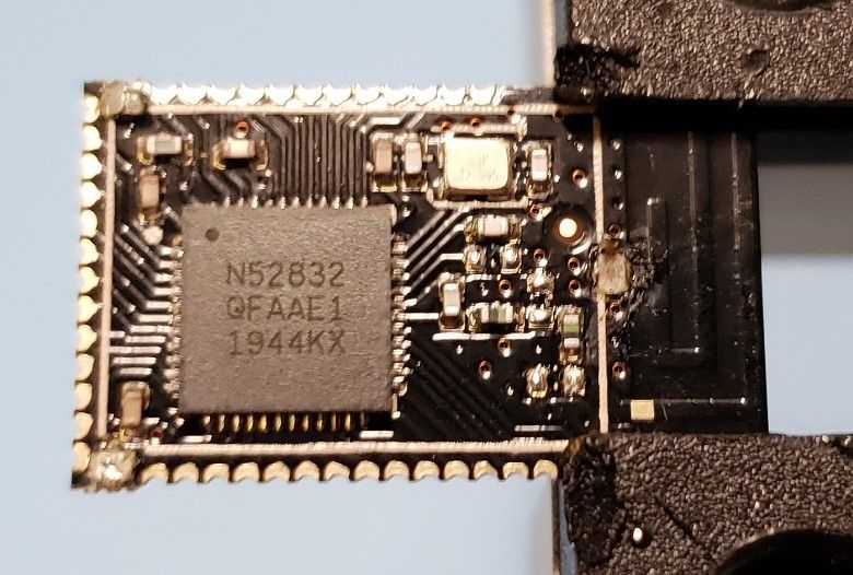
    MS50SFB noShield.jpg


  • Hero Member

    A Version 2 of the micro:bit is due to be released this month: https://www.electronicsweekly.com/news/products/bus-systems-sbcs/microbit-version-2-educational-computer-now-runs-ai-gets-loudspeaker-2020-10/

    It's based around the 64Mhz, 128Kbyte RAM nRF52833: https://www.nordicsemi.com/Products/Low-power-short-range-wireless/nRF52833

    Version 2 will include a speaker and a microphone and will apparently make use of bluetooth for wireless communication. The EW article also says it will support a "microbit-radio protocol". Also, the EW article says that Javascript will run on it.

    By itself it's not that interesting, but for someone looking to get started, it's another way in.


  • Hardware Contributor

    @NeverDie said in nRF5 action!:

    A Version 2 of the micro:bit is due to be released this month: https://www.electronicsweekly.com/news/products/bus-systems-sbcs/microbit-version-2-educational-computer-now-runs-ai-gets-loudspeaker-2020-10/

    It's based around the 64Mhz, 128Kbyte RAM nRF52833: https://www.nordicsemi.com/Products/Low-power-short-range-wireless/nRF52833

    Version 2 will include a speaker and a microphone and will apparently make use of bluetooth for wireless communication. The EW article also says it will support a "microbit-radio protocol". Also, the EW article says that Javascript will run on it.

    By itself it's not that interesting, but for someone looking to get started, it's another way in.

    No revolution on the radio sidde, bluetooth and microbit-radio were already here in first version of micro:bit. But use of speaker and microphone in addition to much larger memory is quite nice for students learning with it, it will open a lot of possibilities. Open source schematic and programs can also be a great base to make open source sound-related sensors and actuators compatible with MySensors.


  • Before exploring compatibility, I ordered a few nRF52805 modules from Ebyte, but I'm still waiting on delivery https://www.aliexpress.com/item/1005001709688444.html

    Any way to know if NRF52805s are compatible with the current core, sandeepmistry/arduino-nrf5? With MySensors?
    https://infocenter.nordicsemi.com/topic/struct_nrf52/struct/nrf52.html?cp=4l

    What is the hypothetical process of adding a new NRF52 variant? Where would I start?


  • Hero Member

    @ncollins The sandeepmitry library has incomplete coverage, but what it does provide is access to the nRF5 registers. From there you can do whatever it is that you want to do by manipulating the registers directly. That makes it closer to assembly language, at least in thought process, than the confortable arduino library support you may be accustomed to.
    I haven't tracked the arduino or adafruit implementations. Maybe by now they have better library support? Alternatively, mbed and sager and probably others have their own library support for it, so there's always that which you can look into. Come to think of it, IIRC, Arduino simply adopted the mbed platform for the nRF52 rather than roll their own, which was a rather unusual move. That may mean it may never be completely "arduino" in the same way other arduino platforms are.


  • @NeverDie I see.

    Say the Arduino mbed route supports my nRF module, would MySensors library need to be rewritten? Any idea how coupled it is to the sandeepmistry core?


  • @ncollins said in nRF5 action!:

    would MySensors library need to be rewritten?

    Yes.
    mbed is RTOS, sandeepmistry's core runs on bare metal instead.


  • @monte thanks

    I'm struggling with choosing the direction of the next steps in my diy sensor journey.

    My focus has moved exclusively to nRF5 boards given the compact size, performance, and cost. I don't have range, penetration, or interference concerns, so I don't utilize any of the LoRa support in MySensors.

    Given the ubiquitous support of BLE, recent advancements in mesh and long range capabilities, continued investment, widespread adoption...it might make more sense for someone with my use case to explore moving to a BLE based network.

    I'm assuming there isn't much to gain by layering MySensors on top of BLE. And I'm not sure it makes sense for the MySensors community to expand and maintain support for boards capable of MySensors use, but primarily intended for BLE use. Especially, considering a significant majority of the community is completely satisfied with ATMEGA + (NRF24 / LoRa).


  • Hero Member

    @ncollins If you have the gumption to do it, it might open up some interesting new possibilities. In the past programming bluetooth was a bit daunting, but it seems like some of the newer tools may be easier to learn: e.g. https://learn.adafruit.com/introducing-the-adafruit-nrf52840-feather/bluefruit-nrf52-api


  • @NeverDie said in nRF5 action!:

    https://learn.adafruit.com/introducing-the-adafruit-nrf52840-feather/bluefruit-nrf52-api

    Ha, I ordered one yesterday. I'll mess around and report back.


  • Where to start?


  • Just started testing my new NRF52805 breakout board. I added a new generic variant to sandeepmistry/arduino-nRF5, added a new board to mysensors nRF5, now I'm testing compatibility.

    This new NRF52805 chip is interesting. Way stripped down compared to the rest of the NRF5 line. No PWM, no LPCOMP, only 10 GPIO (maybe 8 usable).

    But, it's cheap, ~$2.50 for the EBYTE BT104-BT5005 module, compact, and appropriate for most low-power use cases.

    Interestingly, the chip does not support the current MySensors default, but deprecated, data rate of 250Kbps. Today I also learned that modules can only communicate on the same data rate. So I created a ESP8266 + NRF24L01+ gateway at MY_RF24_DATARATE RF24_1MBPS, and it worked!

    Still need to test a few things:

    • I2C
    • SPI
    • Power consumption

    If all goes well, I'll submit the merge requests and publish this board schematic on openhardware sometime in the next week.
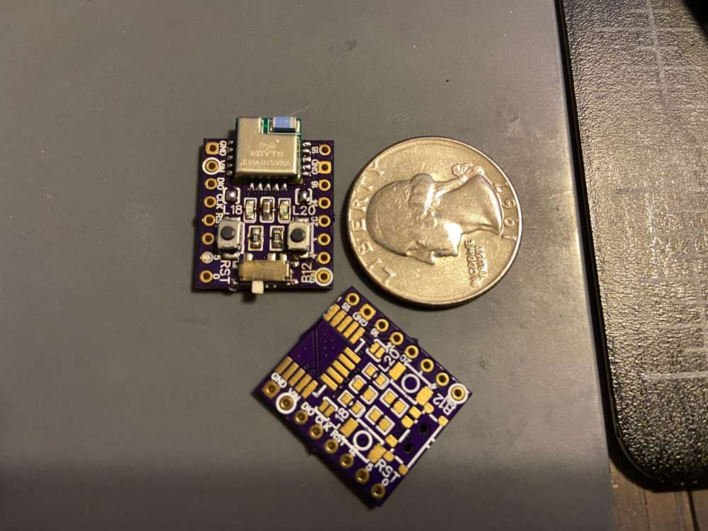
    IMG_1291.jpg


  • @NeverDie I spent the last week really deep diving into NRF BLE & NRF networking capabilities.

    Some things I learned:

    • BLE is a great way for low power communication with a dedicated, physically close parent node
    • BLE alone does not establish a network, just a link to a central/gateway node. Giving the limited range, that means having multiple gateways, and dedicated links (painful, inflexible)
    • That led to the creation of BLE Mesh. I found this article from Integra Sources to be really helpful as they talk through the real world limitations they experienced trying to go to production with it. In summary, BLE Mesh is a "managed flood" which quickly leads to network storms if not optimized
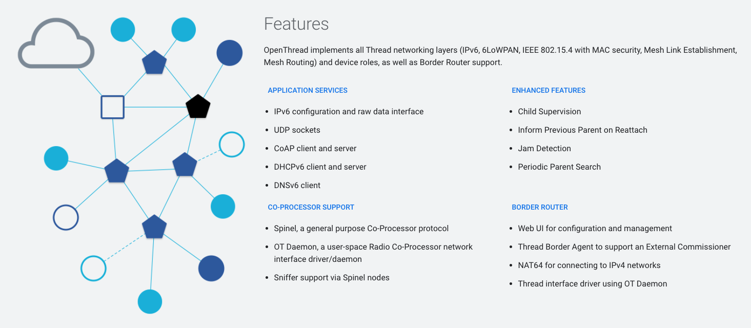
    • Then I found OpenThread
      Screen Shot 2020-12-18 at 9.53.32 PM.png
    • After messing around for few days, I found this guide https://github.com/kyberpunk/openthread which really simplifies getting started. Two docker containers: OpenThread Border Router (sensor network gateway) and MQTT-SN (UDP6 MQTT bridge to MQTT Broker). I was able to setup a network with two NRF52840 dongles + NRF52840 DK, and post messages to my MQTT instance within a couple of hours.

    OpenThread is supported on the the NRF52840, NRF52811, NRF52833, as well as 10-15 chips from other vendors.

    I really like the ability to route via IP and the fact that all of the nodes communicate with common, well known protocols. I like the secure-by-default approach, and the built in tools for administering networks (commissioning new nodes).

    I'm going to keep exploring this route, seems promising....


  • Update on my NRF52805 Breakout:

    • I2C is now working, just a few small changes to select the right interface
    • Power consumption looks good, around 1.8uA. The Si7021 module is reading 2.5uA in isolation.
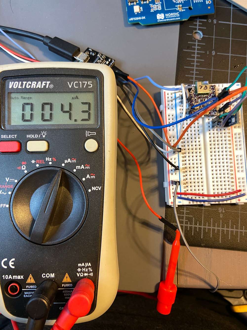
      IMG_1292.JPG

    Just need to test SPI and figure out a clever name for the board, and should be good to go.


  • Hero Member

    @ncollins said in nRF5 action!:

    Just started testing my new NRF52805 breakout board. I added a new generic variant to sandeepmistry/arduino-nRF5, added a new board to mysensors nRF5, now I'm testing compatibility.

    This new NRF52805 chip is interesting. Way stripped down compared to the rest of the NRF5 line. No PWM, no LPCOMP, only 10 GPIO (maybe 8 usable).

    But, it's cheap, ~$2.50 for the EBYTE BT104-BT5005 module, compact, and appropriate for most low-power use cases.

    Interestingly, the chip does not support the current MySensors default, but deprecated, data rate of 250Kbps. Today I also learned that modules can only communicate on the same data rate. So I created a ESP8266 + NRF24L01+ gateway at MY_RF24_DATARATE RF24_1MBPS, and it worked!

    Still need to test a few things:

    • I2C
    • SPI
    • Power consumption

    If all goes well, I'll submit the merge requests and publish this board schematic on openhardware sometime in the next week.
    IMG_1291.jpg

    Great work! For the gateway you might want to look into Ebyte E01-2G4M27D (https://www.aliexpress.com/item/4000536940861.html?spm=a2g0s.9042311.0.0.60da4c4dGywFPS), which should have better receive sensitivity than the usual nrf24L01 because it includes an LNA.


  • Hero Member

    @ncollins said in nRF5 action!:

    @NeverDie I spent the last week really deep diving into NRF BLE & NRF networking capabilities.

    Some things I learned:

    • BLE is a great way for low power communication with a dedicated, physically close parent node
    • BLE alone does not establish a network, just a link to a central/gateway node. Giving the limited range, that means having multiple gateways, and dedicated links (painful, inflexible)
    • That led to the creation of BLE Mesh. I found this article from Integra Sources to be really helpful as they talk through the real world limitations they experienced trying to go to production with it. In summary, BLE Mesh is a "managed flood" which quickly leads to network storms if not optimized
    • Then I found OpenThread
      Screen Shot 2020-12-18 at 9.53.32 PM.png
    • After messing around for few days, I found this guide https://github.com/kyberpunk/openthread which really simplifies getting started. Two docker containers: OpenThread Border Router (sensor network gateway) and MQTT-SN (UDP6 MQTT bridge to MQTT Broker). I was able to setup a network with two NRF52840 dongles + NRF52840 DK, and post messages to my MQTT instance within a couple of hours.

    OpenThread is supported on the the NRF52840, NRF52811, NRF52833, as well as 10-15 chips from other vendors.

    I really like the ability to route via IP and the fact that all of the nodes communicate with common, well known protocols. I like the secure-by-default approach, and the built in tools for administering networks (commissioning new nodes).

    I'm going to keep exploring this route, seems promising....

    Very inspiring! I've had high hopes for Thread, and from your report it sounds like maybe now is a good time to jump in.


  • @NeverDie Thanks, and good call on the Ebyte NRF24 with LNA. I have a few laying around that I've been meaning to incorporate into a generic multi-sensor gateway/repeater node. If they're always connected, might as well collect environment data and maybe motion too.


  • @ncollins

    There's this nice HAT for the Raspberry Pi you might find interesting πŸ™‚ : https://gitlab.com/electronutlabs-public/indrium-pi-hat

    On another topic, I would honestly like to see MySensors using OpenThread or BLE Mesh transport...


  • @Avamander That would make a great gateway. I believe I read a getting started guide by the creator of that Pi Hat, Playing with Thread and MQTT-SN on Nordic nRF52840. The tutorial is a little outdated now, but it's a good overview of the process of setting up a Thread network. There is a lot of good content on that blog.

    I agree, but it is still not clear to me what the appropriate relationship between MySensors and OT / BLE Mesh is. It seems there is a lot of overlap in functionality. While I prefer to focus on the NRF5 series, a majority of the community is using ATMEGA328 and NRF24, or LoRa modules, which wouldn't support OT / BLE.

    At the very least, I'd like to see MySensors tap into some more of the advanced NRF5 capabilities: OTA, NFC.

    There are also a few examples of NRF5 modules running in dual mode: BLE + OT. If it's possible to run 2.4GHz + BLE in parallel, then there is potential to create a MySensors bridge device.

    Or maybe leveraging BLE to configure MySensor nodes at runtime: modifying sleep duration, send frequency.

    Given the abundance of storage and memory on the NRF5 devices, it is also feasible to create something like Tasmota / ESPeasy for MySensors. Use the same firmware on every node, have the MySensors gateway/controller manage and push configuration templates. Given the great work on MySensors NodeManager and the SmartSleep functionality, it seems like the foundation is already in place.


  • I wanted to write that Softdevice and ESB are not compatible for use at the same time, but then decided to fact check myself. Seems like now you can use Softdevice and ESB simultaneously. You can either disable softdevice in program, or use Timeslot API to manage access to radio of different protocols.
    https://infocenter.nordicsemi.com/index.jsp?topic=%2Fsds_s140%2FSDS%2Fs1xx%2Fconcurrent_multiprotocol_tsl_api%2Ftsl_usage_examples.html&cp=4_5_3_0_8_2
    https://devzone.nordicsemi.com/f/nordic-q-a/55847/priority-level-overlap-between-softdevice-and-esb
    https://jimmywongiot.com/2020/06/22/radio-timeslot-api-for-the-multiple-protocols/
    If this is doable I can't think of a reason, why mysensors shouldn't use softdevice.


  • (Been away for a while, but saw this and thought I should chime in...)

    @monte - I can confirm that this is true. I have custom nRF52832 boards with bootloaders and SoftDevices (S132) that are all currently happily running MySensors code too - I needed the bigger memory footprint AND FOTA updates, so...

    As you suggest, you have to disable the SoftDevice before MySensors takes ownership of the radio otherwise there are problems. And depending on how/where you stack things, make sure that @d00616's awesome arduino-NVM layer (pseudo-EEPROM implementation) isn't going to write over anything important. I used Adafruit's FreeRTOS implementation as a starting point, but I'm not sure I fully understand what I've done in the scheduler.

    I've not used the Timeslot API myself, but instead do a sort of hard-switch between the two for configuration, BLE OTA updates, etc. So for example, I have a switch in HA to put any individual node into "DFU OTA via BLE" mode - just like in the Nordic examples - then I can use their app to upload new firmware, update the SoftDevice, etc. and then reboot.

    Hope that made sense.

    Also @NeverDie, on the threads and meshes - I've had good success with Apache MyNewt. Their BLE Mesh implementation (using NimBLE) was relatively straightforward to work with. I made a 5x node test mesh with Publishers and Subscribers, everything provisioned using secure Network and App keys using Nordic's nRF Mesh app. Press a button on one node, all the others do something, etc. At that point, I'm not sure how useful it is to implement the MySensors protocol on top of that, but rather just choose a Publisher to act as a Gateway to your Home Automation software of choice.


  • @acb so you just compile mysensors code with sofdevice chosen in options, and everything works? That's great news!
    Do you mean you use FreeRTOS with mysensors also? So I guess you are using adafruit's bootloader then?


  • @monte - No, not quite. I'll have to dig back into my local codebase. I use PlatformIO, but I remember having to modify one or more arduino-NVM files to make them compile for Adafruit's nRF52 BSP, something else with how the digital pins were defined (probably minor) elsewhere and of course update MyMainNRF5.cpp to work with their FreeRTOS scheduler. I remember that last part being a bit painful to debug - even with a JLink - but the nodes are pretty solid now.

    I can do a diff later this evening if you're interested...?

    Yes, Adafruit went with using an RTOS to manage their SoftDevice interfacing. I suppose there are pros/cons to that, but their support was definitely a pro! The useful part is being able to disable it cleanly (!) and then being able to jump back into it when it's safe to do so. FOTA updates with Nordic's app are always solid.

    And yes, I've got a custom version of their bootloader running on my boards. Nothing fancy - different pins, buttons, LEDs, etc. I might have modified one or two other bits here and there, but their base should be a good enough starting point.

    What boards are you using? And how are you programming them?


  • @acb said in nRF5 action!:

    I can do a diff later this evening if you're interested...?

    Yes please, I think I'm not the only one who will appreciate your code πŸ™‚
    I have a bunch of 51822's but wanted to get into 52840. I have paused my research of NRF5 for some time, while I am finishing my other work, but I would like to have more complete experience with NRF5 than what is now provided by mysensors.
    I guess FreeRTOS is a way to go, when you have far mo complex MCU then atmega, and far more capable.
    I hope that mysensors core team will consider moving forward to more complex, but more powerful architecture.


  • @monte: Okay, sorry for the delay in getting back to you about this (- FWIW: UK went into another national lockdown, schools closed, so it’s been pretty crazy here the last few days...!)

    I’ve dug back into my original code, done some experimenting and have tried to get down to a minimal set of steps necessary to get MySensors code to play "nicely" with a SoftDevice. Hopefully it’ll be helpful as a starting point. But note that minimal is not optimal - or even the best - see more on that below.

    Caveats aside...

    As far as prepping the nRF52832 goes, this HEX file will load the chip with the following MySensors-compatible regions either β€œin-mind” or in-place:

    0x00000 to 0x00FFF -   4K MBR Region, currently up to 0xAFF.
    0x01000 to 0x25FFF - 148K SoftDevice Region, currently with S132 up to 0x2514F.
    0x26000 to 0x6FFFF - 272K Application Region, bootloader intelligently fills.
    0x70000 to 0x70FFF -   4K VirtualPage? managed by arduino-NVM.
    0x74000 to 0x7EFFF -  44K Bootloader Region, currently custom up to 0x78FCB.
    0x7F000 to 0x7FFFF -   4K β€œEEPROM” Area? managed by arduino-NVM.
    

    It’s best to get the bootloader to load the application code (via an FTDI) since it knows where to put it, otherwise you’re doing it manually with a JLink, etc.

    The linked bootloader also expects:

    UART TX on P0.11
    UART RX on P0.12
    USR BTN on P0.15
    BLE DFU on P0.16
    MCU RST on P0.21
    

    Other optional, but useful pins are:

    LED1 on P0.13
    LED2 on P0.08
    

    Once the above-linked HEX has been flashed (using JLink, BMP, etc.), you can boot the nRF52832 into a state where it is expecting a DFU over UART by grounding USR BTN (P0.15) and resetting (ground P0.21 briefly). LED1 will fade up and down slowly to confirm the new state.

    Or you could do this over BLE by grounding both USR BTN and BLE DFU (P0.16) and resetting. LED1 and LED2 will fade up and down more quickly to confirm.

    I’ve found the custom tools in Adafruit’s nRF52 BSP for Arduino to be pretty solid for FTDI uploading, but YMMV. Otherwise, it’s Nordic’s nRF Toolbox app.

    (Note that if you do go with Adafruit’s BSP, you can call built-in functions in your Sketch code like enterSerialDfu() and enterOTADfu() to perform the same button operations as above.)

    As far as prepping MySensors goes, these are (I think) the minimum files and modifications needed to make things work. In summary:

    1. Either comment out the define check for NRF5 right at the bottom of MySensors/drivers/NVM/Flash.h (or define it somewhere) so that the flash driver gets compiled. This is the only file that uses that define, AFAIK.

    2. If you’re using Adafruit’s nRF52 BSP (recommended), you have to make sure MySensors uses the correct pin assignment array. Quick hack is to just replace line 37 of nrf5_wiring_digital.c (MySensors/hal/architecture/NRF5/drivers) with ulPin = g_ADigitalPinMap[ulPin];

    3. Finally, you will probably want to play around with the implementation of MySensors and FreeRTOS in this MyMainNRF5.cpp file (replacing the one in MySensors/hal/architecture/NRF5).

    This last file is where FreeRTOS is being used to create a sort of Arduino-like structure with a loop_task() being added to the scheduler that contains both the usual setup() and loop() functions you’ll probably be familiar with from Arduino IDE land - setup() is run by MySensors inside the _begin() function.

    Note that this is NOT the best or lowest power way to do this! But it is (possibly) the fastest way to get your existing MySensors sketches up and running.

    Remember that this is now an RTOS running on the MCU. So ideally, you probably want to completely dispense with system ticks and move to a setup that only uses interrupts, timers, callbacks, etc. to get the lowest possible power, depending on what you’re trying to do in your Sketch. If you want a quick-and-dirty low power hack, just lower the configTICK_RATE_HZ define in FreeRTOSConfig.h (Adafruit nRF52 BSP) to something like 4 (Hz) or so - but that not the β€œright” way to do it...

    However, that’s outside the scope of this (now, not-so) little post. If you want to dig deeper, I’d suggest familiarising yourself with FreeRTOS and reading through this low power Github issue with Adafruit’s implementation and the associated links mentioned in it - this page from FreeRTOS on Low Power Tickless Idle Support is good too. Here’s an example of an Arduino Sketch using tasks, timers and interrupts - but using Bluetooth - that illustrates a loop-less implementation.

    I’ve tinkered down to the 2 or 3 Β΅A region with MySensors using the RTC, portsense interrupts, etc. and you can, of course, go sub-Β΅A using a custom SYSTEM OFF sleep implementation and an external nA region RTC.

    I can try to put together a better MySensors integration, if folk are interested. It’ll take time though, especially now that we’re locked down for the next month…

    Anyway, hope that was helpful. Any questions, I’ll do my best to respond with what I know.

    (P.S. Oh, and you'll need the latest MySensors development branch to get the most stable nRF52832 radio implementation.)

    Have fun! πŸ™‚


  • @acb thank you for such complete answer!
    One more question for now, is this standard, or modified bootloader?
    And how many additional steps do I need to take to make this work on nrf52840?


  • @monte - Glad you found it helpful!

    The bootloader I linked to is a custom (modified) one to fit the board I'm using. I remember tinkering with things like buffer sizes to make large BLE DFUs more reliable - I'd have to dig back into my notes to be sure...

    But I believe Adafruit's standard nRF52 Feather should keep approximately the same memory regions - which is the "main" hurdle. I think the only other potential issue for the nRF52832 was their use of a BOOTLOADER_SETTINGS region at 0x7F000, so you'll have to check that it's not in the way of the arduino-NVM sections. On the Adafruit Bootloader side, it's all linker-related, nrf52.ld is the file I think.

    Or you can, of course, modify arduino-NVM to pick it's sections somewhere else, say, underneath the bootloader, for example. Just be sure to limit how much it erases from there.

    I remember nRF52840 being trickier because Adafruit had (and used) both the BOOTLOADER_SETTINGS region (this time at 0xFF000) and a BOOTLOADER_CONFIG region (at 0xFE000 - 2K, or something like that...) which they used for USB VID+PID, UF2 family, etc.

    I've got a similar (custom) Adafruit-based bootloader I made for Nordic's nRF52840 Dongle that works with MySensors, if you're interested?

    I couldn't get Nordic's default Dongle bootloader to play nicely with MySensors (at the time). They sign their bootloader so you can't replace it through nRF Connect without a JLink/BMP/etc. - you have to wipe the chip completely - which creates another problem. The bootloader also needs to set REGOUT0 in the UICR to 3v so you can see your LEDs and debug the thing without level-shifting (the default is 1.8v). Anyway, it does all work (eventually!) - I've currently got a Dongle serial gateway and Dongle nodes running in various places. Oh, you'll need to up the data rate too, since the 840 doesn't support the MySensors (deprecated) default of 250kbps.

    Does that help at all?

    What nRF52840 board(s) do you have?


  • @acb I have a couple of Ebyte's E73 modules. I also have BMP, so it shouldn't be a problem.
    If you could share your bootloader for 52840 it would be a great start for my tinkering.

    @acb said in nRF5 action!:

    I couldn't get Nordic's default Dongle bootloader to play nicely with MySensors (at the time).

    So have you gotten any success eventually?
    Once again, thank you for such extensive information πŸ™‚ I hope others will appreciate it too.


  • Hero Member

    @monte said in nRF5 action!:

    I hope others will appreciate it too.

    Yes! Any examples which shed light on how to write a custom bootloader for the nRF52 would be greatly appreciated.


  • I just gave this design to pcb fab and cant wait to test it out. I made and tested a similar board using nrf52840 but soldering aQFN package is a nightmare and i needed to cancel quite abit of pins to increase the success chance.
    So this design is based on nrf52832with a normal QFN package which is easy to solder and that allowed me to breakout every single pin (except P0.07). Can be powered with a single cell lipo or USB port and managed to fit in a charger for it with a charging indicator led. It has a voltage divider to measure the battery but it can be desoldered if the pin is needed for another function.
    Comes with PA and LNA just like my nrf52840 test and had to follow quite abit of design recommendations from the datasheet.
    Some pins are compatible with adafruit 52832 circuit design just in case if i want to use their bootloader. Like reset, DFU, 2 different leds are connected to the same pins as in their board design. Also theres a selector 0 ohm resistor between pcb and external antenna.
    I will report when i receive and test it!
    832.JPG


  • @monte, @NeverDie - Took some time this weekend to take a look at this and used my previous post as something of a template; hope it helps...

    Re: Nordic’s default Dongle bootloader - I never managed to get it to play nicely with MySensors and so abandoned it completely in favor of a modified version of Adafruit’s again, since I was already familiar with it from my nRF52832 work. It would have been nice if Nordic had revealed their private key to move/replace their bootloader, but I get it, I figure they’d rather you bought their DK.

    This is the custom bootloader (.HEX file) my Nordic nRF52840 Dongle nodes currently use. You’ll need to completely wipe any current Dongle (or EByte E73 module) using a JLink/BMP before flashing. It has the following MySensors-compatible regions either β€œin-mind” or in-place:

    0x00000 to 0x00FFF - 4K MBR Region, currently up to 0xAFF.
    0x01000 to 0x25FFF - 148K SoftDevice Region, currently with S140 up to 0x25DE7.
    0x26000 to 0xEFFFF - 807K Application Region, bootloader will intelligently fill.
    0xF0000 to 0xF0FFF - 4K VirtualPage? managed by arduino-NVM.
    0xF4000 to 0xFD7FF - 38K Bootloader Region, currently custom up to 0xFC01F.
    0xFD800 to 0xFDFFF - 2K Bootloader Config, currently custom up to 0xFD857, 88B.
    0xFF000 to 0xFFFFF - 4K β€œEEPROM” Area? managed by arduino-NVM.

    The linked bootloader will of course expect the same pin connections as the Dongle. The important ones are probably only:

    LED1_YLW_GREEN on P0.06
    
    LED2_RGB_RED   on P0.08
    LED2_RGB_GREEN on P1.09
    LED2_RGB_BLUE  on P0.12
    
    USR BTN on P1.06
    BLE DFU on P1.10
    
    MCU RST on P0.21
    

    The bootloader supports CDC, DFU and UF2 upload modes. So the first time you flash the bootloader and reset, you can then mount it as a removable drive with UF2 support for drag-and-drop uploading of applications and/or new bootloader images, etc.

    It should also appear as a usual COM port via it’s CDC descriptors, enabling FTDI-like uploading through PlatformIO/Arduino IDEs. And as before, you can perform DFUs over BLE through a manual combination button-press - more on that below...

    Also as before, the bootloader shows the upload state through the LEDs, but note that on the Dongle, the LEDs are all active LOW - i.e. drive a logic zero (β€˜0’) to illuminate the LED(s). If you’d like a version of the bootloader where the LEDs are all active HIGH, let me know and I’ll try to dig out my old environment and compile something - you can do this yourself though… πŸ˜‰

    Manually entering these upload states is similar to the nRF52832. Uploading via FTDI works as you would expect. Ground P1.06 (USR BTN) and reset (ground P0.21, MCU RST, briefly) and the nRF52840 will expect a DFU over USB either via it’s COM port or UF2 if mounted. On the Dongle, LED1 will fade up and down slowly and I think the RGB LED goes green if mounted.

    For DFUs over BLE, ground P1.06 (USR BTN) and P1.10 and reset. I chose P1.10 because it’s right next to a ground pin on the Dongle and I just soldered another push switch to it. LED1 fades up and down more quickly together with the RGB LED turning blue to confirm. Uploading is via Nordic’s nRF Toolbox app and again, if you’re using Adafruit’s BSP you’ll get the built-in enterSerialDfu() and enterOTADfu() sketch functions to perform the same button operations as above.

    As far as prepping MySensors goes, the same applies as above with the nRF52832, only this time you’ll need to up the data rate to 1Mbps or higher, as I mentioned earlier.

    I could upload Arduino IDE and PlatformIO board variants for the Dongle if you’d like. But it’s straightforward enough to create variants for your specific board. If you’re using the Dongle, probably the most useful thing I have to hand is this code-snippet for enabling the regulator:

    // Set REGOUT0 to 3V mode
    // https://devzone.nordicsemi.com/nordic/short-range-guides/b/getting-started/posts/nrf52840-dongle-programming-tutorial
    if ((NRF_UICR->REGOUT0 & UICR_REGOUT0_VOUT_Msk) ==
        (UICR_REGOUT0_VOUT_DEFAULT << UICR_REGOUT0_VOUT_Pos))
    {
        NRF_NVMC->CONFIG = NVMC_CONFIG_WEN_Wen;
        while (NRF_NVMC->READY == NVMC_READY_READY_Busy);
    
        NRF_UICR->REGOUT0 = (NRF_UICR->REGOUT0 & ~((uint32_t)UICR_REGOUT0_VOUT_Msk)) |
                            (UICR_REGOUT0_VOUT_3V0 << UICR_REGOUT0_VOUT_Pos);
    
        NRF_NVMC->CONFIG = NVMC_CONFIG_WEN_Ren;
        while (NRF_NVMC->READY == NVMC_READY_READY_Busy);
    
        // System reset is needed to update UICR registers.
        NVIC_SystemReset();
    }
    

    If you stick this in an initVariant function in your variants.cpp, the Adafruit nRF52 BSP will call it as part of main.

    I think that's everything - I hope it was helpful - any questions, I’ll do my best to respond a bit faster this time!

    Famous last words... πŸ˜‰


  • Hero Member

    @acb Thanks for your post!

    My nRF52 skills have gotten a bit rusty, so in case you're no longer around when I circle back to this toopic in the future, I'm going to jump the gun and ask you now so that your answer can be memorialized here and then suitably curated by Hek for years to come: How exactly do you ensure that your bootloader is loaded into the proper bootloader memory segments and not treated like a regular program and stored in ordinary, non-privlidged program memory? I'm guessing it's accomplished through a linker directive of some kind? If you could share even a brief simple example here on how to implant the bootloader code where it needs to be, I'm sure it would be immensely helpful to anyone who wants to create a custom bootloader of their own. πŸ˜‰

    Actually, it seems you did offer a summary of how to do it when you wrote "Manually entering these upload states is similar to the nRF52832. Uploading via FTDI works as you would expect. Ground P1.06 (USR BTN) and reset (ground P0.21, MCU RST, briefly) and the nRF52840 will expect a DFU over USB either via it’s COM port or UF2 if mounted. On the Dongle, LED1 will fade up and down slowly and I think the RGB LED goes green if mounted.", but again a step-by-step actual example, with demo files, would really drive it home. Now, some people might consider that much detail would constitute a "no thinking required" guide and therefore overkill, but I'd prefer overkill to underkill any day. I'm sure at least some others who are reading this would rather have s complete demo example that's too basic than have to puzzle over a missing or vague step. It may not seem like it's missing or vague to you now, but believe me if you ever have to switch to a different project for a while, it might not look anywhere near as obvious or as familiar when you come back to pick up where you left off.

    So, if I can prevail upon you to put together even a very simple demo, I'd volunteer right away as a test subject to see if I could replicate it. And if I can, then you can be confident that if you had to shelf your work then you could come back years later and resume without help just based upon re-reading your own notes. 😎


  • Thanks @NeverDie, I appreciate that.

    Okay, well, the short answer to your question is yes, it’s a β€œlinker directive” or rather a series of them, usually a file with the .ld extension. There’s normally a general stack/heap/etc. one called nrf_common.ld in Adafruit’s BSP, and then an architecture-specific one: nrf52.ld I think for the nRF52832 and nrf52840.ld for, well, I bet you can guess! πŸ˜‰

    This architecture-specific linker directive contains the memory locations for things like the MBR, ram region for the bootloader, initialized and (shared) non-init RAM, bootloader settings/configuration, MBR parameters, etc. The bootloader itself can of course read this memory allocation/settings/configuration data and then load any new application code or indeed new bootloader code wherever it needs to be. That’s why it’s best to let the bootloader perform the FOTA, either via serial or BLE.

    Now I’m guessing here, but ideally, the arduino-NVM library that sort of emulates AVR EEPROM for MySensors could just read this information too and store it’s virtual EEPROM pages around these allocations. Currently, I think it just tries to determine the top application page address from the UICR and then allocate the pages based on that. It’s been a while since I looked at the code, so it might have changed. Essentially, it’s trying to find where the bootloader starts (if there is one) and allocate some pages a bit back from there to be safe.

    In theory, a large enough application could overwrite this area - that’s why it’s not the best solution as I mentioned earlier - but if you reach that point, you’ve gotten so close to the bootloader with your application code, you might be in (other) trouble anyway! πŸ˜‰

    As far as a step-by-step with actual example code, demo files, etc. I’m more than happy to do it but it’ll take me some time. And would be helped if you could specify a particular board you’d like me to target (especially if I have one lying around), e.g. Nordic’s nRF52840 Dongle, Ebyte module, etc?

    The other side of this is the FreeRTOS side. Would you like examples for the lowest possible power?

    It seems like that’s how folk like these devices to operate. Going down around 2Β΅A in bare System ON sleep (nRF52832) and around 300nA in bare System OFF sleep requires more involved MySensors code modifications, due to (among other things!) how FreeRTOS takes care of the power management when idling, use of the RTC(s), how it handles ISR callbacks, attaches interrupts, etc. By β€œbare” I mean no additional sensors, just, for example, a button or internal RTC (only in System ON) to wake it.

    Does all, or at least some, of that make sense? πŸ™‚


  • Hero Member

    @acb said in nRF5 action!:

    As far as a step-by-step with actual example code, demo files, etc. I’m more than happy to do it but it’ll take me some time. And would be helped if you could specify a particular board you’d like me to target (especially if I have one lying around), e.g. Nordic’s nRF52840 Dongle, Ebyte module, etc?

    Yes to nRF52840. Dealer's choice as to which nRF52840 module--i.e. I'm neutral, so whatever is more convenient for you. I suppose for others reading this the dongle might be a good choice though.

    The other side of this is the FreeRTOS side. Would you like examples for the lowest possible power?

    Is FreeRTOS definitely required? I suppose I could live with it, but as a simple demo even just some simple code that did nothing more than blink an LED and which resided where the bootloader out to be and which got loaded automatically from protected memory on reset as though it were a real bootloader is sufficient. If I knew how to do that one small thing, then I presume I could extend it to be a real wireless bootloader instead of just an LED blinker. I'm just missing the info on how to put code into the privileged and normally protected bootloader location. I'm hoping it's actually pretty simple and straightforward and not something lengthy and complex like the way the Nordic SDK advocates doing it.


  • @ncollins Hey any update on your NRF52805 Breakout work? I've got a couple of the Ebyte modules that I have been playing around with. Found your pull request on GitHub for board support in sandeepmistry's nrf5 core. Wondering if you got any further as the pull request hasn't been merged and it would be great to see Arduino support for these modules.


  • @Jon-Raymond I kinda got hung up on the last conversation in the merge request and haven't looked at it since. Let me push the changes I have to address the other comments, then try to figure out how to best handle that last bit.


  • @ncollins That's great, thanks!


  • @Jon-Raymond I pushed my latest changes, posted a question to the merge about next steps.


  • @ncollins Here is my version of a breakout for the nRF52805.

    PXL_20210331_040531693.jpg

    Been playing around with your fork/pull request and I do have one question.

    Should there be a SoftDevice for this? According to Nordic it needs either S112 or S113 for BLE to function? Right now your pull request only has the "None" option in the SoftDevice menu.

    Is this something you have run into? Do you have any example code that you are running on this module? Thanks again for your work in getting this device supported.


  • @Jon-Raymond the nRF52805 should support the S112 and S113 soft device, but I removed it from the menu because I never tested it and didn't intend to immediately use it.

    Digging through sandeepmistry/arduino-nrf5, it looks like S112 and S113 aren't included in the SDK. It might be easy enough to just drop in two new folders, then update boards.txt.

    e0a17f79-2edd-4750-a4c5-21ff33c8a1a0-image.png

    6fba7886-f4c1-4b5b-aaa9-9e699ab7ff4e-image.png

    (Just an example of how I would add a soft device option to the dropdown, these would have to match up with whatever is in the sdk)

    I would recommend opening an issue/question on https://github.com/sandeepmistry/arduino-nRF5, specifically asking the best way to add a new softdevice to the library. If it's straightforward, I can work with you to get those changes incorporated and, hopefully, included in the merge request.


  • Thanks @ncollins. I created the issue as requested.


  • @Jon-Raymond Well, not seeing a lot of activity in the repo.

    I took a very long shot at adding support https://github.com/nikolac/arduino-nRF5/tree/nrf52805-s112-support.

    I was able to flash the softdevice, but I haven't tested or even uploaded a working sketch (sloppy). Feel free to mess around and test. If it works for you, I do the same for S113.

    Biggest question I have is around figuring out the proper values for the "linker scripts" https://github.com/nikolac/arduino-nRF5/blob/nrf52805-s112-support/cores/nRF5/SDK/components/softdevice/s112/toolchain/armgcc/armgcc_s112_nrf52805_xxaa.ld


  • Hero Member

    I've ordered an Adafruit Clue, which should be arriving today. It utilizes the nRF52840. Judging from the reviews, Adafruit has done a nice job of supporting both the Clue and the Clue's vast number of built-in sensors with 1. good adafruit library integration along with lots of example programs and 2. the adafruit bootloader, making it easy for beginners to program the Clue via the familiar Arduino IDE. For those just getting started, I think it's likely to be a more satisfying experience and a gentler introduction to nRF5x than buying a nRF5x DK and then wondering what to do next.


  • Hero Member

    I received the CLUE and it works very nicely--just like you'd expect a proper Arduino board to work: some basic hardware abstraction, a familiar easy-to-use Arduino IDE, easy familiar compiles, easy familiar uploads, and easy familiar access to serial input/output.

    Time flies! This thread is already 5 years old, but I'm re-reading it now to refresh myself on all the little details that I've forgotten.


  • Hero Member

    Anyone here programmed an nRF52805? I made a breakout board for one and was planning to program it using the J-LINK on an nRF52-DK:
    nrf52805.JPG
    but because there is no official DK for the nRF52805, there is no "board" for it, and so I'm unclear as to how exactly it is supposed to be programmed. Segger Embedded Studio makes no mention of the nRF52805 at all, as near as I can tell. Fortunately, our old friend Sandeep Mistry does appear to have a core for it: https://github.com/sandeepmistry/arduino-nRF5/tree/master/cores/nRF5/SDK/components/device
    so that may help save the day. Unfortunately, the nRF52805 upload instructions from Nordic are a hassle: https://devzone.nordicsemi.com/guides/short-range-guides/b/getting-started/posts/developing-for-the-nrf52805-with-nrf5-sdk Is there no easier way?


  • Hero Member

    Reporting back: As a first step I programmed an external nRF52832 by blinking P.18 using this method for wiring it up: https://devzone.nordicsemi.com/f/nordic-q-a/14058/external-programming-using-nrf52-dk This method of wiring is worthy of note all by itself, because prior to now the conventional wisdom was that the target mcu had to be separately, externally powered for the J-link on the DK to recognize it properly. With the illustrated approach to wiring it up, though, you can power it from the DK itself.
    better_wiring.png
    Nice.

    That worked just fine. Then I tried uploading exactly the same code, using the same wiring scheme, to the nRF52805. I even erased it beforehand just to be sure.
    According to J-Link, both the erasure and the subsequent upload were successful. However, P.18 does not blink. So, it would appear that a straightforward upload by treating it like an nRF52832 just isn't going to work, even just for blinking a particular pin. Argh! I feared as much. Disappointing!


  • Hero Member

    Success! Treating the nRF52805 like an nRF52810 and uploading to it from Segger Embedded Studio's IDE using Nordic's nRF52 SDK's PCA10040e board definition, then pin P.18 blinks using the same sketch that blinked P.18 on the nRF52832. I'm reporting back with this good news, because I haven't seen it tried or documented anywhere before. At least for this modest first attempt, this simple spoof works! At $2.50 each, these tiny nRF52805 modules with their trace antennas are a good value.

    By the way, the compiler that's built into Segger Embedded Systems is super fast compared to gcc.


Log in to reply
 

Suggested Topics

70
Online

11.5k
Users

11.1k
Topics

112.7k
Posts