nRF5 action!
-
What size pads are you guys using for your SAMD21 land pattern? Mine don't look right. The SAMD21 datasheet didn't actually give a land pattern. It just gave the size of the legs, and so I just made up a land pattern that was close to that. Looks too small compared to others that I'm seeing (e.g. on the Hackaday).
@NeverDie said in Minimalist SAMD21 TQFP32 Pro Mini:
What size pads are you guys using for your SAMD21 land pattern? Mine don't look right. The SAMD21 datasheet didn't actually give a land pattern. It just gave the size of the legs, and so I just made up a land pattern that was close to that. Looks too small compared to others that I'm seeing (e.g. on the Hackaday).
Nevermind. I found the answer on page 10 of http://www.atmel.com/Images/Atmel-8826-SEEPROM-PCB-Mounting-Guidelines-Surface-Mount-Packages-ApplicationNote.pdf
-
I don't see any decoupling capacitors or ferrite beads on the USB data circuit. According to the schematic ( https://cdn.sparkfun.com/datasheets/Dev/Arduino/Boards/sparkfun-samd21-mini-breakout-v10.pdf), USB_D- and USB_D+ just connect directly to pins PA24 and PA25 on the MCU.
@NeverDie said in Minimalist SAMD21 TQFP32 Pro Mini:
I don't see any decoupling capacitors or ferrite beads on the USB data circuit. According to the schematic ( https://cdn.sparkfun.com/datasheets/Dev/Arduino/Boards/sparkfun-samd21-mini-breakout-v10.pdf), USB_D- and USB_D+ just connect directly to pins PA24 and PA25 on the MCU.
I saw that on the Adafruit board I think, and on the SenseBender gateway.
-
you should not add decoupling /ferite beads to the D+/D- lines.. At most, add a protection resistor of 30R (or there about) inline, to limit current flow. Also you can add a USB protection circuit with diodes externally..
The ferite bead / capacitors on the sensebender, is between the cable shield, and gnd on the device, to limit EMI on the cable shielding..
-
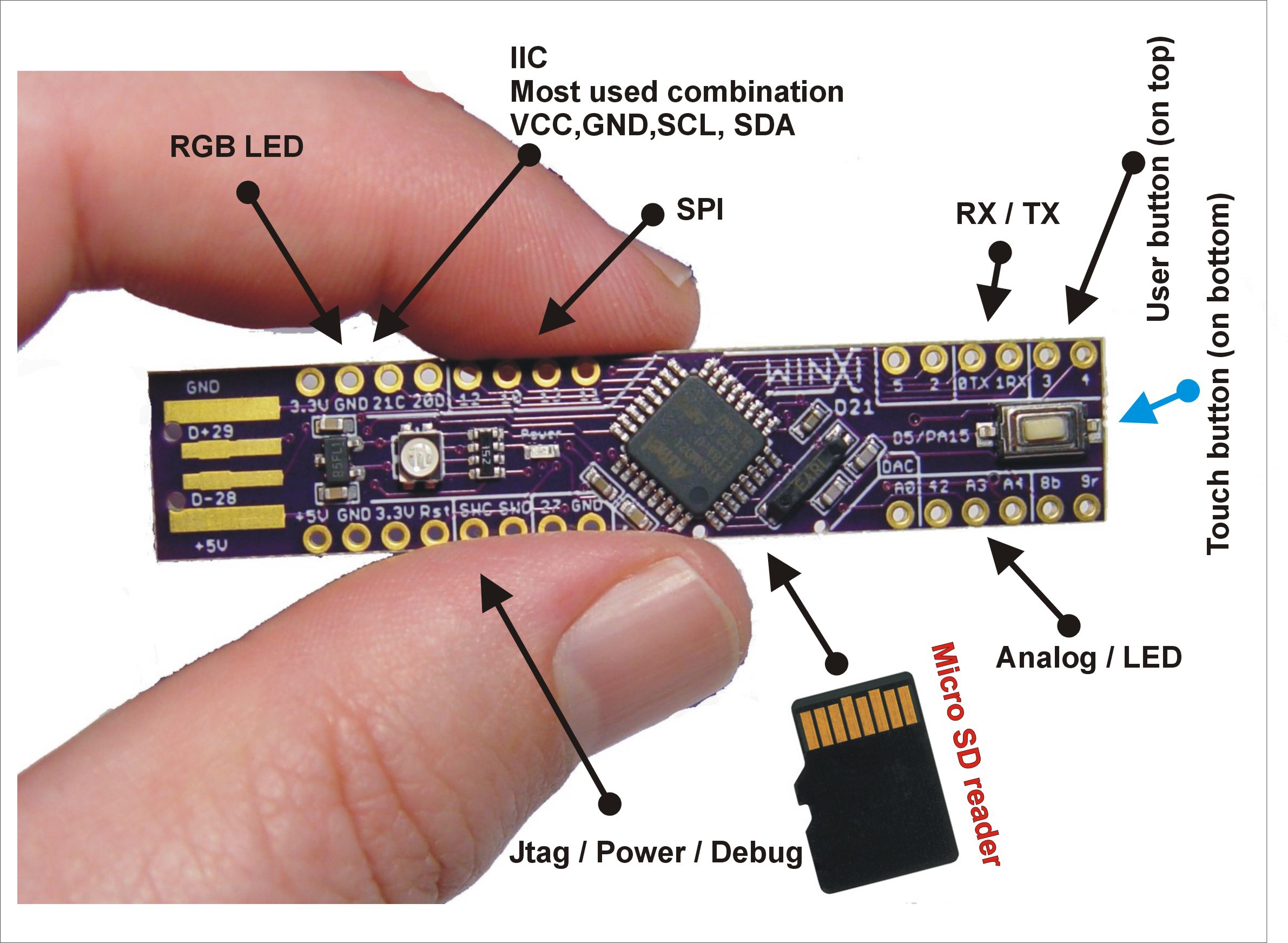
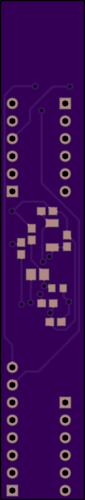
Just realizing that if I'm going to hand patch the 4 SWD wires onto the board anyway, then I really don't need an SWD block. Consequently, I'm now thinking the Hackaday guy had the right idea with making his entire node the width of a USB connector:
-
Just realizing that if I'm going to hand patch the 4 SWD wires onto the board anyway, then I really don't need an SWD block. Consequently, I'm now thinking the Hackaday guy had the right idea with making his entire node the width of a USB connector:
-
@NeverDie >> I'm now thinking the Hackaday guy had the right idea with making his entire node the width of a USB connector:
Really good idea. Just plug it into your box.
-
@Terrence
Yes, and by making the node the width of a USB connector, there's no wasted PCB that you'd get if the PCB were wider. -
@NeverDie Event though there seem to be many benefits to going narrow, what about enclosure sizes, where longer may not be as good as a smaller square?
@Terrence said in Minimalist SAMD21 TQFP32 Pro Mini:
@NeverDie Event though there seem to be many benefits to going narrow, what about enclosure sizes, where longer may not be as good as a smaller square?
I'll cross that bridge if I come to it. :)
Meanwhile, what I'm wondering is: just how wide should the PCB be? I tried looking up USB dimensions, but I get conflicting info:

I also tried measuring some with a micrometer. I think it's going to be something around 12mm. My PCB needs to be a minimum of 12.12mm wide in order to avoid pads of the SAMD21 being too close to the edge of the PCB. Is that too wide, or is it within tolerance?
-
i saw this board too, it's nice one ;) and we can see there is nothing for usb... no fuse, no esd protection, and you touch it and play with it when it's plugged.
I know this works like this, i did it too for proto. i think maybe computers usb ports are perhaps better protected now, but who knows what can happen, so on my side i prefer to have some basic security to not fry my usb ports :grimacing:
If you're doing a proto, this pcb size should be ok, but if it's for using with a radio, especially RFM, then the radio module is wider than the board. I know it because i made my atsam RFM dongle for serial gw.Last advice if i can :), it's a good practice, to route usb datalines in a // way, and like differential lines, meaning they should be almost the same length (with a few % error). That will work sure, without too much care on a small board like that, but still good to know. you should have a tool in your CAD software for this.
@scalz said in Minimalist SAMD21 TQFP32 Pro Mini:
if it's for using with a radio, especially RFM, then the radio module is wider than the board.
Good point. That might make connecting it a bit difficult! I suppose this form factor is a better match for a surface mount NRF24.
-
Just realizing that if I'm going to hand patch the 4 SWD wires onto the board anyway, then I really don't need an SWD block. Consequently, I'm now thinking the Hackaday guy had the right idea with making his entire node the width of a USB connector:
@NeverDie said in Minimalist SAMD21 TQFP32 Pro Mini:
Just realizing that if I'm going to hand patch the 4 SWD wires onto the board anyway, then I really don't need an SWD block. Consequently, I'm now thinking the Hackaday guy had the right idea with making his entire node the width of a USB connector:
I notice that the Hackaday guy's labeling of D- and D+ as pins 28 and 29 conflicts with what Sparkfun has. Sparkfun has those as pins PA24 and PA25 respectively. Is he wrong? I know from direct experience that the Sparkfun board works, so for now I'm going with the Sparkfun pin mapping.
I hear that the PIC MCU chips have a switching fabric that allows you to map any logical pin to any physical pin. I wish the Atmel chips had that. Do maybe these ARM chips have some of that as well?
-
yes it depends what ARM mcu you use, some have more freedom regarding pin mapping and peripherals, but atsam can do that too. Very useful.
There are some rules for atsam how to change the mapping for spi or other periph, versus arduino core files and datasheet. But if you don't want to dig in that, you can just follow a mapping from a board which already exists in Board manager. -
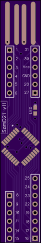
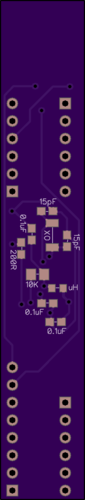
I finished the first pass, and it looks as though everything will fit:
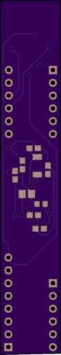
A bit more work to do, but this is the approximate form it would take.
-
@Terrence said in Minimalist SAMD21 TQFP32 Pro Mini:
@NeverDie NRF or RFM?
Neither. This is just the MCU. If I can get it to run blink, then as a next step I'll add a radio.
It's basically a subset of the sparkfun board, but in a different form factor, with a different USB, and all in 2-layer rather than 4-layer. This will be my first ARM board, so I'm just trying to keep it as simple as possible. The razzmatazz can come later.
-
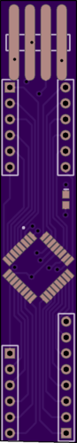
I polished up the USB and re-positioned the headers so they'd fit on a breadboard:
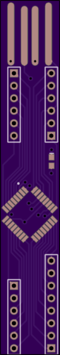
The irony is: after having done all that, I can now more clearly see that it's just not a very efficient form factor. I think for future versions I'll make it not so narrow.
-
I polished up the USB and re-positioned the headers so they'd fit on a breadboard:
The irony is: after having done all that, I can now more clearly see that it's just not a very efficient form factor. I think for future versions I'll make it not so narrow.