nRF5 action!
-
@NeverDie said in nRF5 Bluetooth action!:
4294967295
Also, since 4294967295 equals 0xFFFFFFFF, then bit 31 is a '1', which, according to the datasheet, means the pin is disconnected (see section 14.1.60 PSELRESET[0] of the datasheet for the detail].
-
@NeverDie not sure if you've already noticed, but 4294967295 is the maximum value for an unsigned 32-bit integer. So the value is 0xFFFFFFFF. That often means uninitialized. I don't know why it would be uninitialized though.
@mfalkvidd said in nRF5 Bluetooth action!:
So the value is 0xFFFFFFFF. That often means uninitialized. I don't know why it would be uninitialized though.
There's a chance we may have unwittingly done it ourselves! Remember back to when we were doing an explicit "Erase All"? From the datasheet:
11.5 Erase all
When erase is enabled, the whole Flash and UICR can be erased in one operation by using the ERASEALL
register.Furthermore, from page 29 of the datasheet:
After erasing UICR all bits in UICR are set to '1'.
-
@mfalkvidd said in nRF5 Bluetooth action!:
So the value is 0xFFFFFFFF. That often means uninitialized. I don't know why it would be uninitialized though.
There's a chance we may have unwittingly done it ourselves! Remember back to when we were doing an explicit "Erase All"? From the datasheet:
11.5 Erase all
When erase is enabled, the whole Flash and UICR can be erased in one operation by using the ERASEALL
register.Furthermore, from page 29 of the datasheet:
After erasing UICR all bits in UICR are set to '1'.
@NeverDie said in nRF5 Bluetooth action!:
@mfalkvidd said in nRF5 Bluetooth action!:
So the value is 0xFFFFFFFF. That often means uninitialized. I don't know why it would be uninitialized though.
There's a chance we may have unwittingly done it ourselves! Remember back to when we were doing an explicit "Erase All"? From the datasheet:
This is part of the arduino-nrf5 code -> https://github.com/sandeepmistry/arduino-nRF5/blob/dc53980c8bac27898fca90d8ecb268e11111edc1/cores/nRF5/SDK/components/toolchain/system_nrf52.c#L156
I don't have any idea why this is not included in the binary. When the reset menu is selected then "-DCONFIG_GPIO_AS_PINRESET" is given to gcc.
When system_nrf52.c is completely ignored, then the erratas are not handled.
-
Here is some verbose code which properly sets the registers to use pin P0.21 as the RESET pin:
Serial.println("Testing...");
delay(10000);  //give preparation time to open serial tty
Serial.print(counter);
Serial.print(", PSELRESET[0]=");
Serial.println(NRF_UICR-> PSELRESET[0]);
Serial.print(counter++);
Serial.print(", PSELRESET[1]=");
Serial.println(NRF_UICR-> PSELRESET[1]);

Serial.println();
Serial.println("Write-enabling CONFIG.");
NRF_NVMC->CONFIG=1;  // Write enable the UICR

Serial.println();
Serial.println("Now designating pin pO.21 as the RESET pin.");
NRF_UICR-> PSELRESET[0]=21;  //designate pin pO.21 as the RESET pin
NRF_UICR-> PSELRESET[1]=21;  //designate pin pO.21 as the RESET pin

Serial.println();
Serial.println("Confirming that RESET pin assigment took hold:");
Serial.print(counter);
Serial.print(", PSELRESET[0]=");
Serial.println(NRF_UICR-> PSELRESET[0]);
Serial.print(counter++);
Serial.print(", PSELRESET[1]=");
Serial.println(NRF_UICR-> PSELRESET[1]);

Serial.println();
Serial.println("Return CONFIG to read-only mode.");
NRF_NVMC->CONFIG=0;  // Put the UICR back into read-only mode.
Running it once seems to be good enough, unless there were to occur another "Erase All" or "Burn bootloader" event.
Here is the output from running the code which shows that it succeeded:
Testing... 0, PSELRESET[0]=4294967295 0, PSELRESET[1]=4294967295 Write-enabling CONFIG. Now designating pin pO.21 as the RESET pin. Confirming that RESET pin assigment took hold: 1, PSELRESET[0]=21 1, PSELRESET[1]=21 Return CONFIG to read-only mode. -
Until a more elegant solution can be found, I'm using this in the setup() routine as the workaround:
  if (((NRF_UICR-> PSELRESET[0])==0xFFFFFFFF) && ((NRF_UICR-> PSELRESET[1])==0xFFFFFFFF)) { //if the two RESET registers are erased
    NRF_NVMC->CONFIG=1;  // Write enable the UICR
    NRF_UICR-> PSELRESET[0]=21;  //designate pin P0.21 as the RESET pin
    NRF_UICR-> PSELRESET[1]=21;  //designate pin P0.21 as the RESET pin
    NRF_NVMC->CONFIG=0;  // Put the UICR back into read-only mode.
  }
The code has the positive virtue of not writing to the RESET rregisters unless both registers are erased. That helps ensure that the non-volatile memory does not get worn out prematurely.
-
Until a more elegant solution can be found, I'm using this in the setup() routine as the workaround:
  if (((NRF_UICR-> PSELRESET[0])==0xFFFFFFFF) && ((NRF_UICR-> PSELRESET[1])==0xFFFFFFFF)) { //if the two RESET registers are erased
    NRF_NVMC->CONFIG=1;  // Write enable the UICR
    NRF_UICR-> PSELRESET[0]=21;  //designate pin P0.21 as the RESET pin
    NRF_UICR-> PSELRESET[1]=21;  //designate pin P0.21 as the RESET pin
    NRF_NVMC->CONFIG=0;  // Put the UICR back into read-only mode.
  }
The code has the positive virtue of not writing to the RESET rregisters unless both registers are erased. That helps ensure that the non-volatile memory does not get worn out prematurely.
@NeverDie said in nRF5 Bluetooth action!:
Until a more elegant solution can be found, I'm using this in the setup() routine as the workaround:
  if (((NRF_UICR-> PSELRESET[0])==0xFFFFFFFF) && ((NRF_UICR-> PSELRESET[1])==0xFFFFFFFF)) { //if the two RESET registers are erased
    NRF_NVMC->CONFIG=1;  // Write enable the UICR
    NRF_UICR-> PSELRESET[0]=21;  //designate pin P0.21 as the RESET pin
    NRF_UICR-> PSELRESET[1]=21;  //designate pin P0.21 as the RESET pin
    NRF_NVMC->CONFIG=0;  // Put the UICR back into read-only mode.
  }
The code has the positive virtue of not writing to the RESET rregisters unless both registers are erased. That helps ensure that the non-volatile memory does not get worn out prematurely.
Good news! I've confirmed that doing this does indeed solve the problem I previously had with the EByte nRF52832 module not reacting to a reset on pin P0.21. After inserting the above code block into the nRF52832's setup() routine, I can now, using ESP-LINK, remotely reset an nRF52832 module:
https://www.openhardware.io/view/443/nRF52832-ESP-LINK-Shield-for-ESP8266-Wemos-D1-Mini -
With that issue now settled, I'm moving on to a different topic: what happens if you put the radio into Tx mode, but with an empty buffer (i.e. nothing to send)? In this scenario an RFM69 transmits a continuous pre-amble, and I'm wondering whether the nRF52832 does the same?
With an empty buffer, does it transmit anything at all? Anyone happen to know?The reason I ask is that I want to program the radio to send a continuous signal so as to quickly wake-up a receiver. With packets, there's the lag time of receiving and decoding the packet, rather than just reacting to a high RSSI. In this way, I can use much narrower listen windows and thereby save a lot of current consumption.
-
According to the datasheet, the typical RSSI sample period is just 0.25us. However, what spoils that a bit is that the radio has to come up to speed beforehand.
Anyhow, on the receive side, I now have at least that much working.
-
It looks as though the start-up time for the radio is about 390us. So, it does save a lot of current to first check the RSSI level rather than to always listen for a packet.
-
When I measure RSSI on the nRF52832, I get what seems like a rather odd range of values: between about 94 and 127. If I have no other nodes transmitting, then the RSSI is generally around 100. If I set up another node which deliberately transmits on the same channel, then the RSSI is pegged at 127.
Is that what others here are also seeing? Here's the test code:
uint8_t theRSSI; void loop() { NRF_RADIO->TASKS_RXEN=1; //start revving up the receiver while (!(NRF_RADIO->EVENTS_READY)) {} //busy-wait until radio ready to receive NRF_RADIO->TASKS_RSSISTART=1; //Take exactly one RSSI sample while (!(NRF_RADIO->EVENTS_RSSIEND)) {} //Busy-wait until RSSI sample is completed. theRSSI = NRF_RADIO->RSSISAMPLE; Serial.println(theRSSI); Serial.flush(); sleep(1000); } -
Unfortunately, when I use the above code block and test the current using an oscilliscope, it becomes clear that the radio never actually goes to sleep:
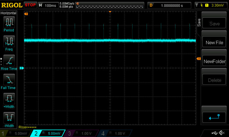
So, to do that, I add the line:NRF_RADIO->TASKS_DISABLE=1; //turn-off the radiojust prior to sleep(100). Doing that largely eliminates the current drain while sleeping:
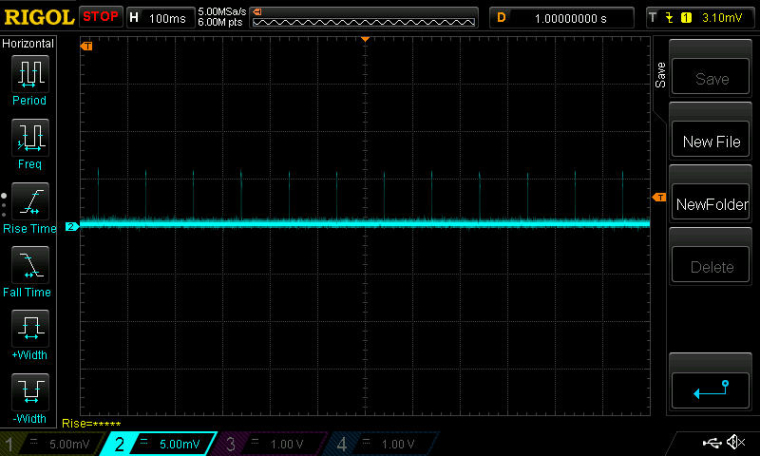
However, if I do that, then the RSSI that gets reported is always 127. Why? Do I need some other way to check the radio states? Maybe STATE from section 23.14.25 STATE of the datasheet would work better?
-
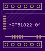
Found a breakout board for the nRF51822-04: https://oshpark.com/shared_projects/zqDQaykJ
-
The datasheet is possibly a bit misleading when it says:
For the RSSI sample to be valid the radio has to be enabled in receive mode (RXEN task) and the reception
has to be started (READY event followed by START task).I'm finding that the radio needs to be in either RXIDLE state or RX state to get a plausible RSSI measurement. I can't get a reasonable RSSI measurement while within the RXRU state.
@NeverDie said in nRF5 Bluetooth action!:
The datasheet is possibly a bit misleading when it says:
For the RSSI sample to be valid the radio has to be enabled in receive mode (RXEN task) and the reception
has to be started (READY event followed by START task).I'm finding that the radio needs to be in either RXIDLE state or RX state to get a plausible RSSI measurement. I can't get a reasonable RSSI measurement while within the RXEN state.
In the ESB code, I use the bitcounter event to start the rssi sample task via PPI. The results are looking plausible.
-
I've found that I get a slightly stronger RSSI signal by about 3dB if I measure it while in the RX state rather than the RXIDLE state. -
@NeverDie said in nRF5 Bluetooth action!:
The datasheet is possibly a bit misleading when it says:
For the RSSI sample to be valid the radio has to be enabled in receive mode (RXEN task) and the reception
has to be started (READY event followed by START task).I'm finding that the radio needs to be in either RXIDLE state or RX state to get a plausible RSSI measurement. I can't get a reasonable RSSI measurement while within the RXEN state.
In the ESB code, I use the bitcounter event to start the rssi sample task via PPI. The results are looking plausible.
@d00616 said in nRF5 Bluetooth action!:
In the ESB code, I use the bitcounter event to start the rssi sample task via PPI. The results are looking plausible.
Do you know of any good PPI tutorials? The datasheet seems awfully skimpy on its explanation of exactly how to use it.
Right now I have RSSI triggers working on the receiver (presently using the MCU, not PPI), but it takes 1400 samples to guarantee not missing any transmissions. That's because of the gap between single shot packets when they get sent. If I can reduce that to one sample, by finding a way to make a transmitter transmit continuously, then that will save a lot of energy on the receiver.
There is a way to do more rapid fire transmission of packets, so that would be the fall-back plan if I can't find a way to, for example, send a continuous preamble.
-
Answering my own question: it turns out that if you enter into TX mode without any payload, it just sends a null packet and returns to TXIDLE. So, it is not like the RFM69, which would simply send an indefinitely long preamble until there's a payload to send.
The goal is to close the gap between packets as much as possible. So, I'm getting some improvement by just immediately switching back into TX mode (to send another null packet) the moment I've confirmed that TXIDLE state has re-occured.
-
As it turns out, using the above method packs the null packets so tightly that I can rely on a single RSSI measurement (instead of 1400 of them) to guarantee that a transmission won't be missed. So, the goal is achieved.
It sounds as though combining PPI with this would drive the energy consumption even lower! :)
-
@d00616 said in nRF5 Bluetooth action!:
In the ESB code, I use the bitcounter event to start the rssi sample task via PPI. The results are looking plausible.
Do you know of any good PPI tutorials? The datasheet seems awfully skimpy on its explanation of exactly how to use it.
Right now I have RSSI triggers working on the receiver (presently using the MCU, not PPI), but it takes 1400 samples to guarantee not missing any transmissions. That's because of the gap between single shot packets when they get sent. If I can reduce that to one sample, by finding a way to make a transmitter transmit continuously, then that will save a lot of energy on the receiver.
There is a way to do more rapid fire transmission of packets, so that would be the fall-back plan if I can't find a way to, for example, send a continuous preamble.
@NeverDie Thank you sharing your experience here. It helps me of better understanding some nRF5 internals. It would be awesome if you share your code.
@NeverDie said in nRF5 Bluetooth action!:
Do you know of any good PPI tutorials? The datasheet seems awfully skimpy on its explanation of exactly how to use it.
To understand PPI you have to be in mind that nearly everything is driven by tasks and events. If you want to do something, you have to start a task like 'NRF_RADIO->TASKS_TXEN=1'. If a task ends it generates an event like 'NRF_RADIO->EVENTS_READY'. You can replace NRF_RADIO with another periphery the registers have an equal naming scheme.
For an event an Interrupt can be enabled with the NRF_RADIO->INTENSET register. Each event correspondents with a bit in that register. In an interrupt, you have to reset the NRF_RADIO->EVENTS_READY register to 0 to allow triggering a new interrupt. For compatibility, you can use the NRF_RESET_EVENT macro in interrupts. This reads back the register on nRF52 to avoid caching effects. Interrupts doesn't matter for PPI :-)
The next fine thing are Shortcuts. Shortcuts are limited to the same peripheral unit. Bits in the NRF_RADIO->SHORTS register are corresponding to a connection between an event and a test. If the event is triggered the task is started. This allows to trigger things like send an packet after the radio is ready. To use this, you have to enable the shortcut in the NRF_RADIO->SHORTS register.
To break the limits of shortcuts, there is the PPI unit with 32 channels. Some of the channels are predefined but interesting to see how things are implemented with BLE. The other PPI channels are flexible. To use one of these channels, you have to write a pointer of your event register, like '(uint32_t)&NRF_RADIO->EVENTS_END' to the NRF_PPI->CH[YOUR_CHANNEL].EEP register and a pointer to your task you want to start in the NRF_PPI->CH[YOUR_CHANNEL].TEP register like '(uint32_t)&NRF_TIMER0->TASKS_START'. Then you have to enable the PPI channel by setting the corresponding bit like 'NRF_PPI->CHENSET |= (1 << COUR_CHANNEL)' that's all.
The nRF52, but not the nRF52 comes with NRF_PPI->FORK[YOUR_CHANNEL].TEP registers. in my reading you can start a second task with this register like writing to NRF_PPI->CH[YOUR_CHANNEL].TEP.
I have no idea about using the PPI Groups.
Arudino provides a PPI library for the primo: http://cdn.devarduino.org/learning/reference/ppi I think we have to use this library to be compatible in the future. I hope there is a chance to port things to arduino-nrf5 back.
Edit: The arduino PPI library is not flexible enough to support radio events. :-(
-
Thanks! At least notionally, the PPI sounds excellent. Presently, if I want to move the radio into a particular state which takes a few state changes to get there, using the MCU with a conservative coding style, I have to initiate the first state change, then busy-wait until the new state is confirmed, then make the next state-change, etc. It sounds as though the PPI is a good fit for this, because it would eliminate the busy-waits. It would automatically transition from one state to the next using just the interrupt scheme you outlined until the target state is reached. Well, at least in theory. Meanwhile the CPU could be doing other things or sleeping. This does sound like a definite improvement, especially for more efficient control over the radio. :)