nRF5 action!
-
However, it does raise the question: if I were to use EVENTS_TICK to trigger some PPI actions, how could PPI also be used to set EVENTS_TICK back to zero so that those actions can be repeated on the next TICK? I haven't yet found an PPI TASKS that can directly manipulate, or even just clear, a particular memory location.
-
Since there are no apparent shortcuts pertaining to the RTC, it looks as though all non-MCU manipulations will have to happen via PPI.
I don't see how to clear a TICK using PPI, so I think the simplest thing would be clearing the counter back to zero if it hits one.
If there's no way to do this basic thing, then I see no way to have a "listen mode" equivalent for the nRF52832 that runs via PPI.
So, adapting what @d00616 wrote earlier, maybe the PPI code to do that would be:
  #define CHANNEL (1)
  NRF_PPI->CH[CHANNEL].EEP = (uint32_t)&NRF_RTC0->COUNTER;  //when COUNTER goes from zero to one.
  NRF_PPI->CH[CHANNEL].TEP = (uint32_t)&NRF_RTC0->TASKS_CLEAR;  //clear COUNTER back to zero.
  NRF_PPI->CHENSET = (1 << CHANNEL) ;
Well, it does compile, but it doesn't work. :( I think it doesn't work because COUNTER is not an event.
Unfortunately, changing COUNTER to EVENTS_TICK fails also:
  NRF_PPI->CH[0].EEP = (uint32_t)&NRF_RTC0->EVENTS_TICK;  //when TICK occurs.
  NRF_PPI->CH[0].TEP = (uint32_t)&NRF_RTC0->TASKS_CLEAR;  //clear COUNTER back to zero.
  NRF_PPI->CHENSET=1;   //Enable Channel 0.
Unfortunately, the PPI Example code from Nordic's SDK doesn't look even remotely similar to what we're doing here.
Anyhow, the last thing I tried was this:
  NRF_RTC0->INTENSET=1;  //Allows TICK to create an interrupt.
  NRF_PPI->CH[0].EEP = (uint32_t)&NRF_RTC0->EVENTS_TICK;  //when TICK occurs.
  NRF_PPI->CH[0].TEP = (uint32_t)&NRF_RTC0->TASKS_CLEAR;  //clear COUNTER back to zero.
  NRF_PPI->CHENSET=1; //enable Channel 0.
hoping that it might make a difference, but it still fails. Why? What is wrong with it?
-
@NeverDie said in nRF5 Bluetooth action!:
EVENTS_TICK
From the datasheet:
15.6 Events
Events are used to notify peripherals and the CPU about events that have happened, for example, a state
change in a peripheral. A peripheral may generate multiple events with each event having a separate
register in that peripheral’s event register group.
An event is generated when the peripheral itself toggles the corresponding event signal, and the event
register is updated to reflect that the event has been generated. See Figure 10: Tasks, events, shortcuts,
and interrupts on page 68. An event register is only cleared when firmware writes a '0' to it.
Events can be generated by the peripheral even when the event register is set to '1'.
Maybe I don't get the problem here, but the way I see it, you have to actively write a '0' to the event register to clear it, but in fact it shouldn't matter, because the timer can nevertheless generate an event.
@Uhrheber said in nRF5 Bluetooth action!:
you have to actively write a '0' to the event register to clear it
This is right. I later confirmed it (see above), but thank you for the passage in the datasheet. I could have sworn that somewhere the DS said that events were read-only, but the passage you quoted contradicts that recollection. So, thank you again.
Any thoughts on the PPI question (directly above your post)?
-
So, you want to shut the CPU down, leaving only RTC and PPI running, and generate a wakeup event every 100ms, did I get that right?
I didn't dig that far into the datasheet, and also I don't have any board for testing (yet).Also, I didn't check whether the debugger will survive a power down/up cycle.
Does it? -
So, you want to shut the CPU down, leaving only RTC and PPI running, and generate a wakeup event every 100ms, did I get that right?
I didn't dig that far into the datasheet, and also I don't have any board for testing (yet).Also, I didn't check whether the debugger will survive a power down/up cycle.
Does it?@Uhrheber said in nRF5 Bluetooth action!:
So, you want to shut the CPU down, leaving only RTC and PPI running, and generate a wakeup event every 100ms, did I get that right?
Yes. I hope to do more than only just that using the PPI while the CPU sleeps, but that does seem like the first step.
-
So, you want to shut the CPU down, leaving only RTC and PPI running, and generate a wakeup event every 100ms, did I get that right?
I didn't dig that far into the datasheet, and also I don't have any board for testing (yet).Also, I didn't check whether the debugger will survive a power down/up cycle.
Does it?@Uhrheber said in nRF5 Bluetooth action!:
Also, I didn't check whether the debugger will survive a power down/up cycle.
Does it?Don't know. I haven't started using the debugger yet.
-
In this example from Nordic, they're using the RTC's compare interrupt:
http://infocenter.nordicsemi.com/index.jsp?topic=%2Fcom.nordic.infocenter.nrf52%2Fdita%2Fnrf52%2Fapp_example%2Fsolar_beacon%2Fintroduction.htmlAverage current consumption is 19µA, including sensor reading, data transmission and Bluetooth advertizing.
Not too bad, I'd say. -
In this example from Nordic, they're using the RTC's compare interrupt:
http://infocenter.nordicsemi.com/index.jsp?topic=%2Fcom.nordic.infocenter.nrf52%2Fdita%2Fnrf52%2Fapp_example%2Fsolar_beacon%2Fintroduction.htmlAverage current consumption is 19µA, including sensor reading, data transmission and Bluetooth advertizing.
Not too bad, I'd say.@Uhrheber said in nRF5 Bluetooth action!:
In this example from Nordic, they're using the RTC's compare interrupt:
Yeah, but that part of it is running on the MCU, not the PPI.
void RTC0_IRQHandler(void) { NRF_RTC0->EVTENCLR = (RTC_EVTENCLR_COMPARE0_Enabled << RTC_EVTENCLR_COMPARE0_Pos); NRF_RTC0->INTENCLR = (RTC_INTENCLR_COMPARE0_Enabled << RTC_INTENCLR_COMPARE0_Pos); NRF_RTC0->EVENTS_COMPARE[0] = 0; m_rtc_isr_called = true; } -
Looks as though there is EVTEN, which on the RTC needs to be enabled to get the PPI to work. Shown in Figure 46.
-
Bingo! Added this, and it now works:
NRF_RTC0->EVTENSET=1; //enable routing of RTC events to PPI.:)
-
More good news. As far as the PPI is concerned, an event such as OVRFLW is still just as active as if it had been cleared, even if it hasn't. Here's the proof:
  NRF_RTC0->TASKS_TRIGOVRFLW=1;

  NRF_PPI->CH[0].EEP = (uint32_t)&NRF_RTC0->EVENTS_OVRFLW;  //when RTC overflow occurs.
  NRF_PPI->CH[0].TEP = (uint32_t)&NRF_RTC0->TASKS_TRIGOVRFLW;  //set COUNTER to be near another overflow.
  NRF_PPI->CHENSET=1; //enable Channel 0.
  NRF_RTC0->EVTENSET=B10;  //enable routing of RTC OVRFLW events to PPI.
functions as follows:
https://pastebin.com/Z09e7tMK -
Anyhow, I don't see a way to do an RFM69 style "listen mode" using just the PPI on the nRF52832. I think this may be a dead end.@NeverDie said in nRF5 Bluetooth action!:
Anyhow, I don't see a way to do an RFM69 style "listen mode" using just the PPI on the nRF52832. I think this may be a dead end.It looks like you are implementing a new radio protocol and you are coming forward.
What do you think about forking the MY_RADIO_NRF5_ESB into a new one? The nRF5 code is designed to implement additional protocols for nRF5.
If you remove the address reverse code, there are no OTA conflicts with the ESB protocol. The address width can be enhanced by 2 bits to allow better AES encryption and lager packages.
-
@NeverDie said in nRF5 Bluetooth action!:
Anyhow, I don't see a way to do an RFM69 style "listen mode" using just the PPI on the nRF52832. I think this may be a dead end.It looks like you are implementing a new radio protocol and you are coming forward.
What do you think about forking the MY_RADIO_NRF5_ESB into a new one? The nRF5 code is designed to implement additional protocols for nRF5.
If you remove the address reverse code, there are no OTA conflicts with the ESB protocol. The address width can be enhanced by 2 bits to allow better AES encryption and lager packages.
@d00616 said in nRF5 Bluetooth action!:
It looks like you are implementing a new radio protocol and you are coming forward.
Yes, I'm presently focused on trying to reduce the amount of energy consumed by probably the hardest case of all: a battery/solar/supercap receiver that needs to be both highly responsive (within 100ms) and listening 24/7 without running out of juice. Of course, one can always throw bigger batteries or bigger solar panels at the problem, but I'm first trying to be as ultra efficient as possible so that won't be necessary. The benefit will be smaller size, not to mention lower cost.
I am posting my findings as I go because there is precious little in the way of working examples, so I may yet still be of help to others in that way. From the view count, it does seem that people are reading this thread, even if not many are posting.
-
@d00616 said in nRF5 Bluetooth action!:
It looks like you are implementing a new radio protocol and you are coming forward.
Yes, I'm presently focused on trying to reduce the amount of energy consumed by probably the hardest case of all: a battery/solar/supercap receiver that needs to be both highly responsive (within 100ms) and listening 24/7 without running out of juice. Of course, one can always throw bigger batteries or bigger solar panels at the problem, but I'm first trying to be as ultra efficient as possible so that won't be necessary. The benefit will be smaller size, not to mention lower cost.
I am posting my findings as I go because there is precious little in the way of working examples, so I may yet still be of help to others in that way. From the view count, it does seem that people are reading this thread, even if not many are posting.
@NeverDie said in nRF5 Bluetooth action!:
I am posting my findings as I go because there is precious little in the way of working examples, so I may yet still be of help to others in that way. From the view count, it does seem that people are reading this thread, even if not many are posting.
btw. Thank you for sharing you knowledge here. In my option this is very helpful for me.
-
@NeverDie said in nRF5 Bluetooth action!:
I am posting my findings as I go because there is precious little in the way of working examples, so I may yet still be of help to others in that way. From the view count, it does seem that people are reading this thread, even if not many are posting.
btw. Thank you for sharing you knowledge here. In my option this is very helpful for me.
I think you'll find this interesting:
  NRF_RADIO->TASKS_DISABLE=1;  //sleep the radio
  while (NRF_RADIO->STATE) {}; //wait until radio is DISABLED (i.e. STATE=0);

  NRF_RTC0->TASKS_TRIGOVRFLW=1;  //set COUNTER to trigger an overflow after 16 TICKS.

  NRF_PPI->CH[0].EEP = (uint32_t)&NRF_RTC0->EVENTS_OVRFLW;  //when RTC overflow occurs.
  NRF_PPI->CH[0].TEP = (uint32_t)&NRF_RTC0->TASKS_TRIGOVRFLW;  //set COUNTER to be near another overflow.
  NRF_PPI->FORK[0].TEP = (uint32_t)&NRF_RADIO->TASKS_RXEN;  //turn on the radio receiver
  NRF_RTC0->EVTENSET=B10;  //enable routing of RTC OVRFLW events to PPI.

  //When Radio state TXIDLE is reached, perform an RSSI sample.  There is no shortcut for this, so we must use PPI.
  NRF_PPI->CH[1].EEP = (uint32_t)&NRF_RADIO->EVENTS_READY;  //After event READY, radio shall be in state TXIDLE.
  NRF_PPI->CH[1].TEP = (uint32_t)&NRF_RADIO->TASKS_RSSISTART; //Take the RSSI sample

  NRF_PPI->CH[2].EEP = (uint32_t)&NRF_RADIO->EVENTS_RSSIEND;  //After event RSSIEND, RSSI measurement is finished and radio will be in state TXIDLE.
  NRF_PPI->CH[2].TEP = (uint32_t)&NRF_RADIO->TASKS_DISABLE; //Sleep the radio
  NRF_PPI->CHENSET=B111; //enable Channel 2, Channel 1 and Channel 0.
  sleep(1000000000);  //sleep a million seconds so as not to interfere with current measurements.
It sleeps the MCU, and using just PPI, it wakes up the radio every 16 TICKS (each tick is 100ms) and measures the RSSI. Then it puts the radio back to sleep.
So, looking at the current consumption from a macro viewpoint, it's this:

The taller peaks are when the RSSI measurements happen. Zooming in on one of the RSSI measurements, the current consumption is this:
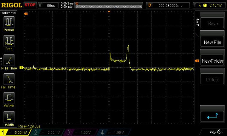
As you can see, very little, and only for a very short time!
-
So all I need now is a way for the PPI to compare the RSSI measurement it obtained above with a threshold benchmark to decide whether or not to wake the MCU, which can take it from there. From that point onward, the regular ESB code could be used. :)
-
Nordic could have taken this a lot farther if they had included some comparison tasks, so that the PPI could make decisions about what to do next. However, I don't see that there are any that can be used for comparing an RSSI measurement against a benchmark. Too bad. :(
-
Great that it works.
But I'm not so convinced about the usefulness of this method, anyways.
I know that a lot of receivers use simple RSSI measurement to implement a low power listening mode, but when you are in a noisy environment, the system will wake up quite often, draining the battery fast. And unless you live in a very remote area, 2.4 GHz IS a noisy environment.