💬 AM612 Passive Infrared Sensor Breakout Board
-
does anyone have a sample sketch for this. i don't understand the whole pin assignment thing well enough to know what the heck i'm doing.
I grabbed the sketch from the 10 year pir but this seems much more geared to the nrf52
-
@waspie just use the same sketch and wiring as in https://www.mysensors.org/build/motion except that AM612 wants 3.3V instead of 5V.
@mfalkvidd
yeah, I don't think that's working. I think I may understand better why not, so correct me if I'm wrong.The low power comparator only works on analog inputs and in the nrf51 board by @NeverDie the SCL marked pin on the board is tied to P0.10 which has no analog input on it.
So, what I think I need to do is cut the trace and re-route it to the INT marked on the board which is tied to P0.03 which is analog 1 (AIN1). At that point then I think I only need to change the line in the sketch to use pin 3 instead of 2.
-
does anyone have a sample sketch for this. i don't understand the whole pin assignment thing well enough to know what the heck i'm doing.
I grabbed the sketch from the 10 year pir but this seems much more geared to the nrf52
-
Thanks.
I'm really not too good at writing arduino code but I did come across this library:
https://github.com/mristau/Arduino_nRF5x_lowPowerIs this something that could be incorporated into the sketch and then use "normal" interrupts?
-
Don't cut your trace just yet. You can use normal interrupts with MySensors and NRF5, at least if you are sleeping the node. I have used the normal Mysensors sleep statement, with interrupts for buttons, and not had to use the LPCOMP. The motion sensor should work similarly. I have used interrupts on P0.27 for a button interupt, which is regular GPIO pin and not an analog pin. I have also used 2 interrupts in the sleep statement, which means the MySensors NRF5 code probably uses GPIOTE instead of LPCOMP for interrupts. Might not be as low power as LPCOMP, but it seems to be more flexible.
I used an NRF52832, haven't tried with a NRF51 board. -
They don't seem to play well and seems like most or any of you guys messing with NRF5x are preferring nrf52.
I have however figured out one problem. Whenever my nrf51 was sleeping i was seeing 1ma current which is a deal killer. I accidentally discovered that disconnecting the st link and replugging it got sleep current to ~5ua. Something about uploading the program puts it in some state whereby it won't sleep properly.
So, I can get it to sleep all the way down now and I'm starting to understand the psel refsel stuff. And, I can make it trigger on p0.03 (an4 or 5, whatever) but its not particularly reliable. I need to get this section right:
void activateLpComp() { NRF_LPCOMP->PSEL=4; // monitor AIN0 (i.e. pin P0.02 on nRF52832 PIR Motion Sensor v607). while (!(NRF_LPCOMP->PSEL==4)) {} //wait until confirmed NRF_LPCOMP->REFSEL=2; // choose 1/2 VDD as the reference voltage while (!(NRF_LPCOMP->REFSEL==2)) {} //wait until confirmed NRF_LPCOMP->ANADETECT=0; //detect CROSS events on PIR detection pin while (NRF_LPCOMP->ANADETECT!=0) {} //wait until confirmed NRF_LPCOMP->INTENSET=B1000; //Enable interrupt for CROSS event while (!(((NRF_LPCOMP->INTENSET)&B1000)==B1000)) {} //wait until confirmed NRF_LPCOMP->ENABLE=1; //Enable LPCOMP while (!(NRF_LPCOMP->ENABLE==1)) {} //wait until confirmed NRF_LPCOMP->TASKS_START=1; //start the LPCOMP while (!(NRF_LPCOMP->EVENTS_READY)) {} //wait until ready NVIC_SetPriority(LPCOMP_IRQn, 15); NVIC_ClearPendingIRQ(LPCOMP_IRQn); NVIC_EnableIRQ(LPCOMP_IRQn); }``` -
It's looking more and more like the code is fine and its the sensors i'm using that are the problem.
I got some BM612 (cheaper) from ali supposedly the same as am612 but they don't seem to work right. It's like they trigger once and then never again. Can't find a data sheet for them...
I hooked up a 312 just for kicks and it seems to be working. I doubt I'll deploy any 312s due to what seems to be a VERY narrow range and plus it doesn't match the profile of the round board etc...
Anyway, wanted to say that i think this is all working as its supposed to I just got a bad batch of sensors or they're slightly different in some way
-
For anyone looking to use @NeverDie 's nrf51 circular board (v9) with this breakout - I'm using the sketch as linked from @Nca78 in this post: https://forum.mysensors.org/topic/6961/nrf5-action/1542
in conjunction with the edit to the file as described in this post:
https://forum.mysensors.org/topic/6961/nrf5-action/1514 (the edit to WInterrupt.c and I'm using version 0.6.0 from sandeep)with just a few minor edits to the sketch from Nca (setting the pin to 10 (sda marked on the circular board).
14ua idle current btw, working like a charm. so far i'm just using a 2032. Trying to figure out a way to strap a cr2450 or 2477 on the back :)
@waspie Apologies for resurrecting this thread after two years. I have quite a few NRF51822 boards with me. I would like to put it to use. Can you please share your code as following these links did not help me compile the sketch. Too many errors. Thanks in advance.
-
@gulsimsur said in 💬 AM612 Passive Infrared Sensor Breakout Board:
I grabbed the sketch from the 10 year pir but this seems much more geared to the nrf52
i don't understand the whole pin assignment thing well enough to know what the heck i'm doing. -
@gulsimsur said in 💬 AM612 Passive Infrared Sensor Breakout Board:
I grabbed the sketch from the 10 year pir but this seems much more geared to the nrf52
i don't understand the whole pin assignment thing well enough to know what the heck i'm doing.@gulsimsur Why are there links to surveyzop in your reply?
-
Thanks for the breakout board, but would it be too much to ask for a revision that can have potentiometers mounted?
so resistors do not need to be changed when tinkering with 15x settings? either SMD or Through-Hole Trimmer0-300k None?,0-1M
-
Or a 12x DIP switch and a Jumper
Jumper for the shortest and longest Time settings
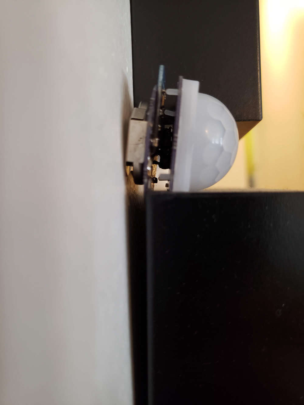
Then pads for installing the 12 Resistors for Time in Seconds the LED / Relay etc is activated for ?also, how were you mounting these boards with no screw holes? just something for the lens cover to clip into
-
Or a 12x DIP switch and a Jumper
Jumper for the shortest and longest Time settings
Then pads for installing the 12 Resistors for Time in Seconds the LED / Relay etc is activated for ?also, how were you mounting these boards with no screw holes? just something for the lens cover to clip into
@MasterCATZ That's a reasonable request. In the future whenever I post a board to openhardware.io, I'll endeavor to include the complete set of KiCAD 6 files needed to make simple changes like this, so then I'm not the bottleneck. However, I did this work, and most of my other work to date, in Diptrace, which AFAIK doesn't allow that kind of easy change by other people.
Meanwhile, if anyone wants to re-do the board and post it with the asked-for change, feel free. Because I don't have that need myself, I won't be doing it, because it involves also spending time finding files in some forgotten archive from 5 years ago in order to resurrect it even before making the change.
In any case, I'm glad that at least some people have found it useful, which is why I posted it in the first place. :-)