What did you build today (Pictures) ?

-
@jeremushka Well, since you ask, you can use a CNC to etch and drill your own PCB: https://forum.mysensors.org/topic/8735/cnc-pcb-milling
A board such as yours would be fairly easy to do that way.
-
@neverdie thanks for the advice. Maybe i can first try pcb transfer with laser printer and chemical etching.
@jeremushka
I have used that several times with good results, though do not make wires too narrow and put them too close to each other. -
Not so much a MySensors build as an example of how even the most basic information can inform changes for the better, in this case space heating.
The system here is fairly basic, an array of DS18B20s, some ultrasonic tank probes and a gas reed sensor, temperature is updated every 5 minutes, the gas updates every 0.05m3...
With winters here down to -20, the first priority last year was insulation, and even though a modern house, the gas bills essentially halved over the year, effectively funding not only the insulation, but replacement axial radiator valves and thermostat heads (Heimeier) to replace the typical arrangement of unknown origin, with spare... But now the MySensors impact..
This autumn's attention turned to the central heating unit, a modern combi unit of good manufacture, installed by a 'certified' heating engineer, but aside what little I knew about condensation boilers and the steep learning curve that followed, I was bemused by the return from the radiator loop almost burning my finger within 10 minutes of the system being fired up. This did not make sense for what I understood of a condensing boilers, which compelled a look inside for the first time, the manual and some googling.The boiler is a 25kW combi with minimum output 7.6kW, the radiators account for ca 13kW at Delta 60 set for 15c drop (previously set ca 20c drop), settings since day one were 65c and the pump was set at max output of 3, last year's -20 resulted in 13.5m3/day gas consumed, not crazy by historical records, but hmmm.
So now comes tinkering with data from MySensors via Domoticz to inform...
Currently the boiler is set at 55c, the pump is on Low (40 v 84w), but the results are surprising - Slower rising temperature when ON, 42 minutes v 25, but gas use dropped from 0.75 to 0.6m3, but here's the kicker from that longer heating time, not only less energy used per cycle, but longer and thereby fewer cycles per day. Current evaluations are between 15 and 20% savings, so thank you to all the MySensors community and contributors.. ;) -
@gohan Sorry, had to edit original post which was too confused on re-reading.
The pump speed curves determine the pressure and flow rate to the radiators, it is the radiators which determine the actual flow for a given temperature drop across them, and speed in raising room temperatures.
The combined flow rate for all the radiators falls within the lower pump curve, any increase in pump speed only increases pressure, NOT speed of heating.
Aside the original mis-set HIGH rate on the pump, there are 3 manual valves left in the system, and no matter how close I try to balance them it was always a compromise, and heat inevitably goes back to the return as pressure increases
Once these are replaced with flow control version in the next week, it will not matter what the pressure is, the radiator flows will be capped at the most efficient level. -
My wife said "I do not want to see "those things""...
Challenge accepted!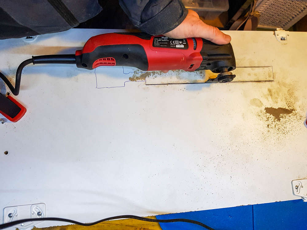
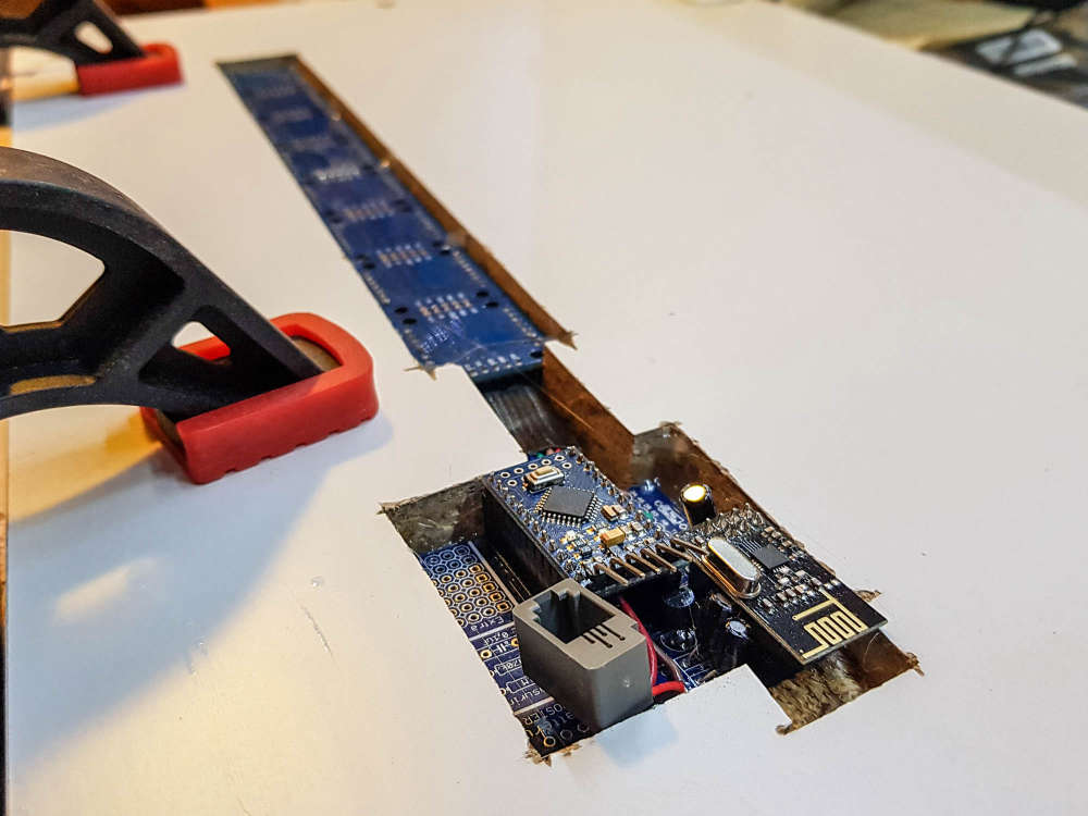
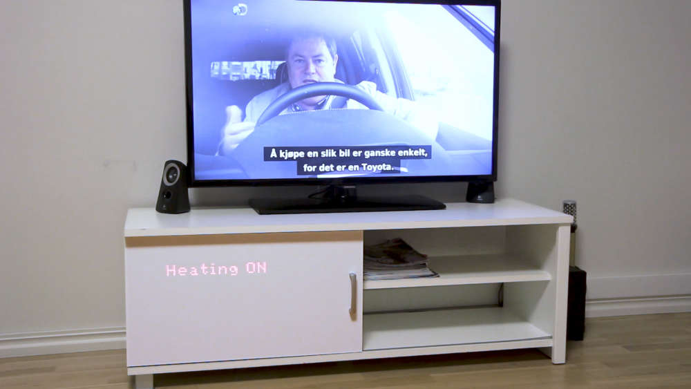
(see the gif in action here https://ibb.co/BCbS2Dc )
C: OpenHAB2 with node-red on linux laptop
GW: Arduino Nano - W5100 Ethernet, Nrf24l01+ 2,4Ghz mqtt
GW: Arduino Mega, RFLink 433Mhz -
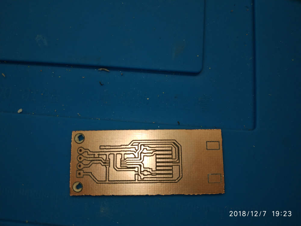
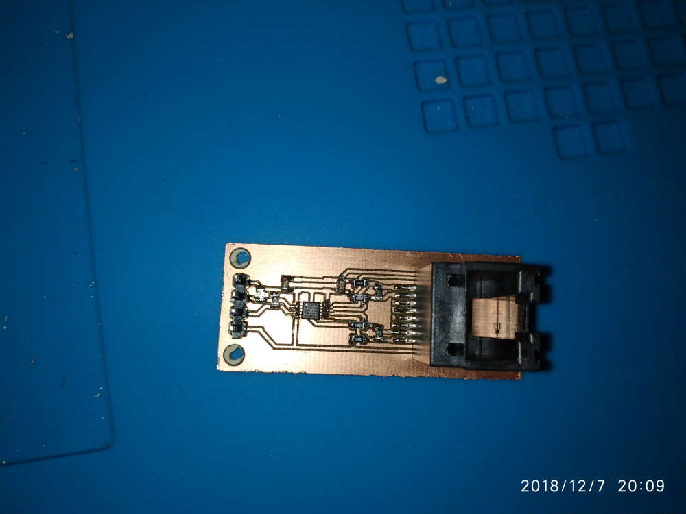
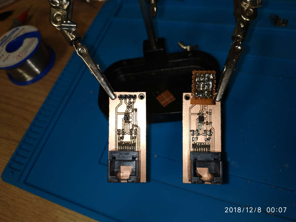
Milled some PCA9615 differential I2C converters for the sensors ouside: magnetometer for the gas meter, temp/hum, baro.
Until now I've used a 7 meter long cable, but whenever the gas water heater fired up the Arduino would just freeze losing the count of gas pulses, I've tried shielded cable but it hasn't solved the issue.
Since Sparkfun's breakout boards are on the wrong side of the pond I decided to make my own.
Really hope the Arduino doesn't lock up anymore.LE. That TSSOP10 was a b*tch to solder 😁
-
My wife said "I do not want to see "those things""...
Challenge accepted!(see the gif in action here https://ibb.co/BCbS2Dc )
@dakipro woaw!!! 👏
-
My wife said "I do not want to see "those things""...
Challenge accepted!(see the gif in action here https://ibb.co/BCbS2Dc )
-
My wife said "I do not want to see "those things""...
Challenge accepted!(see the gif in action here https://ibb.co/BCbS2Dc )
-
@dakipro thank you that's what I planned to do but wasn't sure it would be visible through the plastic layer.
Coupled with capacitive sensors it could give awesome results !@nca78 I used white decorative self adhesive wallpaper, so not sure which plastic you are planing to use, but you can easily test that before mounting I think. If you go for paper/foil, put some one-peace plastic in front of the displays as they (mine) are not perfectly soldered in line, so they are noticeable sa foil will glue to them. Not a big deal for me, but would love "the perfection". But yeah, plastic or some harder material would work awesome I think.
All in all, not difficult project and a very high wow-factor/time-spent value (and waf)
C: OpenHAB2 with node-red on linux laptop
GW: Arduino Nano - W5100 Ethernet, Nrf24l01+ 2,4Ghz mqtt
GW: Arduino Mega, RFLink 433Mhz -
@nca78 I used white decorative self adhesive wallpaper, so not sure which plastic you are planing to use, but you can easily test that before mounting I think. If you go for paper/foil, put some one-peace plastic in front of the displays as they (mine) are not perfectly soldered in line, so they are noticeable sa foil will glue to them. Not a big deal for me, but would love "the perfection". But yeah, plastic or some harder material would work awesome I think.
All in all, not difficult project and a very high wow-factor/time-spent value (and waf)
-
-
Looks great. I'm still happy when I get an 0805 down well. Guess I have to keep practicing.
@nagelc said in What did you build today (Pictures) ?:
Looks great. I'm still happy when I get an 0805 down well. Guess I have to keep practicing.
Try solder paste applied with a thin needle, and a hot air gun at minimum speed (so components don't fly away). Then it's really easy to do SMD :)
-
@nagelc said in What did you build today (Pictures) ?:
Looks great. I'm still happy when I get an 0805 down well. Guess I have to keep practicing.
Try solder paste applied with a thin needle, and a hot air gun at minimum speed (so components don't fly away). Then it's really easy to do SMD :)
@nca78 there many other aspects. I’m using a low temp melting solder paste. I have been using only a top quality (no AliExpress) one from Chipquick. It has to be stored property in the fridge.
Using stencil may help. I’m not using it and have to doze the paste very precisely which is a challenge. This is why my soldering is not 100% consistent, but it works. With 0402 components it is not easy - the pad size is very small.
However, I must admit, 0402 are far too small. In the process, unless your space / lab is very well organised many components are lost. And a good magnifying glass / microscope is a must too. In the future, i’ll try to stick to 0805 or larger - these are a bit larger and more visible.
All in all, this is not as difficult as many people may think. With a little bit of practice, this can be done.
-
Looks great. I'm still happy when I get an 0805 down well. Guess I have to keep practicing.
-
Try this one.
The smallest board I have ever assembled using just a hot fan. A solar battery charger based on BQ25504 from a solar panel. Almost all components are 0402. Far too small for my liking, but can go under the solar panel.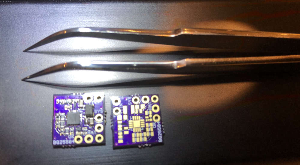
-
Today i recieved my new mini-easy-pcb i posted some info about 3 months ago. This with a breakoutboard-daugher board for all "common" sensors in the MySensors shop. I want to create a small motherboard which can be powered using a battery but also can use the battery for UPS/backup if powered from another daugherboard. The motherboard should be standard and then I would be able to add 1-2 daugherboards to specify the node.
The breakoutboard is just for test, but can be used by newbies offcourse.
My wish is to create the ultimate security sensor running on 12v but with a battery backup. It should include motion, temp, smoke and light.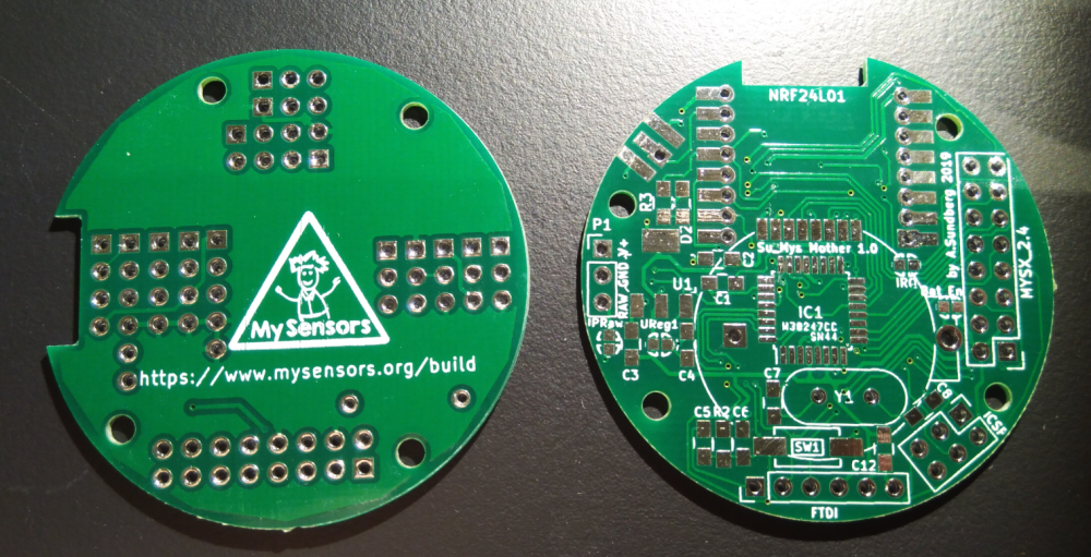
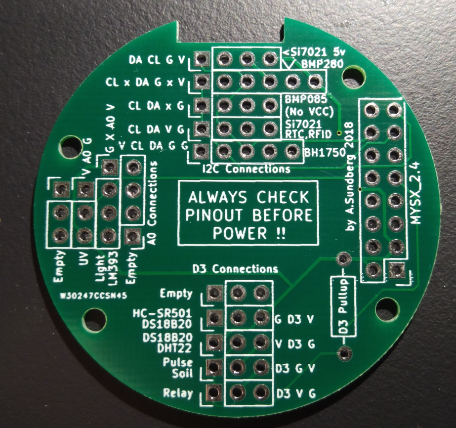
Il will get back in another 3 months when tested ;)
Controller: Proxmox VM - Home Assistant
MySensors GW: Arduino Uno - W5100 Ethernet, Gw Shield Nrf24l01+ 2,4Ghz
MySensors GW: Arduino Uno - Gw Shield RFM69, 433mhz
RFLink GW - Arduino Mega + RFLink Shield, 433mhz -
Today i recieved my new mini-easy-pcb i posted some info about 3 months ago. This with a breakoutboard-daugher board for all "common" sensors in the MySensors shop. I want to create a small motherboard which can be powered using a battery but also can use the battery for UPS/backup if powered from another daugherboard. The motherboard should be standard and then I would be able to add 1-2 daugherboards to specify the node.
The breakoutboard is just for test, but can be used by newbies offcourse.
My wish is to create the ultimate security sensor running on 12v but with a battery backup. It should include motion, temp, smoke and light.Il will get back in another 3 months when tested ;)
@sundberg84 Nice job.