What did you build today (Pictures) ?

-
But it's something...
@sundberg84 you should print the board on paper, stick it on a piece cardboard and cut. Then check if size is good, you can even put the "big" components on it by sticking the pins through the cardboard to make sure you'll have enough space.
-
@sundberg84 you should print the board on paper, stick it on a piece cardboard and cut. Then check if size is good, you can even put the "big" components on it by sticking the pins through the cardboard to make sure you'll have enough space.
@nca78 great tip! But it's more common it's a schematic or footprint error. The outline "should" be the easy part even if I messed up.
-
@fotofieber said in What did you build today (Pictures) ?:
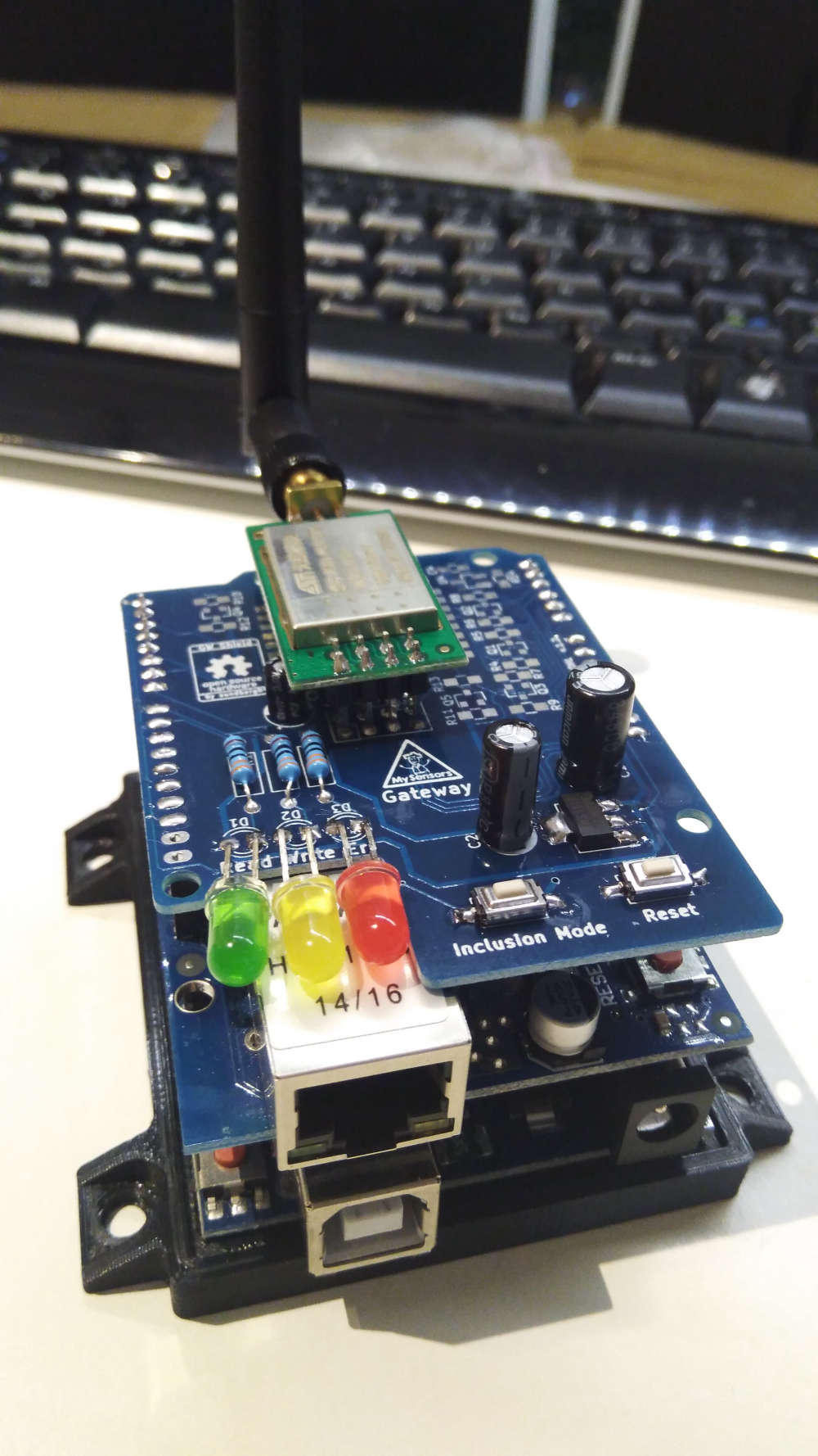
Testing a CCS811 CO2 sensor.
Unfortunately this is not a CO2 sensor. It's only a VOC sensor giving an estimated eCO2 value. It's useful to tell you if your room needs ventilation, but not much more. And as even the VOC part is not calibrated it's only good for relative measurement.
AFAIK the only similar sensors which are calibrated and give absolute values are SGP30 and BME680.
If you want to measure CO2 you need a CO2 sensor and it's going to consume a lot of power, at least too much for a battery powered sensor.[edit] there's also the MiCS-VZ-89TE TVOC sensor, they claim to have a curve of eCO2 not too far from NDIR sensor in their datasheet. But that datasheet is strangely poor in details, they didn't even put any electrical characteristics...
https://sgx.cdistore.com/datasheets/sgx/MiCS-VZ-89TE_V1.0.pdf@nca78 said in What did you build today (Pictures) ?:
@fotofieber said in What did you build today (Pictures) ?:
Testing a CCS811 CO2 sensor.
Unfortunately this is not a CO2 sensor. It's only a VOC sensor giving an estimated eCO2 value. It's useful to tell you if your room needs ventilation, but not much more. And as even the VOC part is not calibrated it's only good for relative measurement.
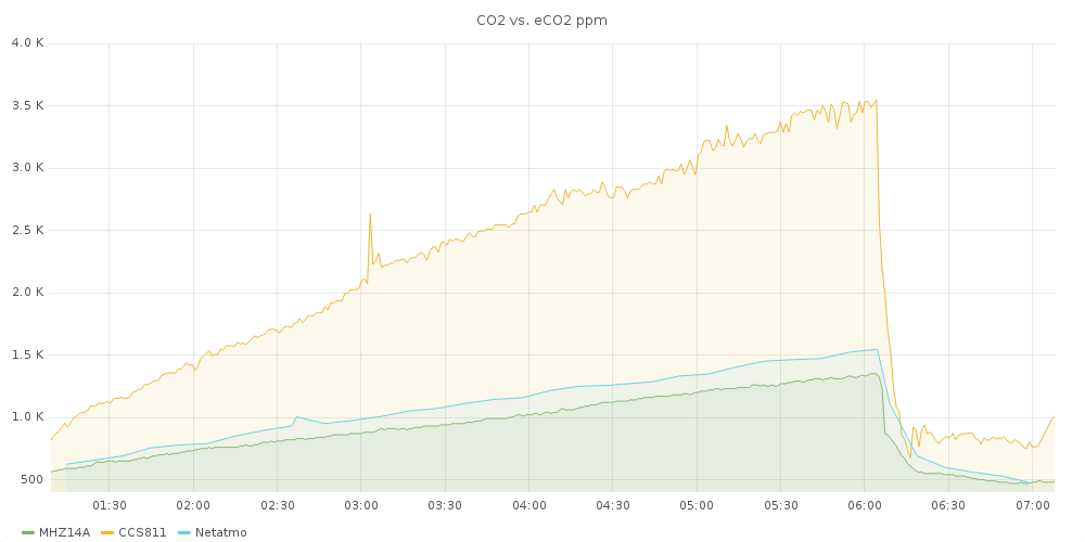
My tests will show, how far away I am with this sensor in my indoor usage scenario.
My Netatmo sensors claim to measure CO2 and are battery powered. They seem to calibrate themselves to the lowest level they measure in 24 hours. This behaviour seems to be similar with the CCS811. The Netatmo sensors seem quite close to my MH-Z14A.
In the datasheet for the CCS811 I have read, that you can't use them in your green house, because of its self calibration. Netatmo may have the same restriction too.
AFAIK the only similar sensors which are calibrated and give absolute values are SGP30 and BME680.
I have ordered a SGP30 some days ago and will test it too. The BME680 needs binary code linked which is a no go for me. (As a gift I would take it into my test setup. :) )
If you want to measure CO2 you need a CO2 sensor and it's going to consume a lot of power, at least too much for a battery powered sensor.
The problem with high power sensors is, that they produce heat, which can make your temperature measurements unusable. :(
As my CO2 sensors have a color led to show air quality, they are mains powered anyway.
[edit] there's also the MiCS-VZ-89TE TVOC sensor, they claim to have a curve of eCO2 not too far from NDIR sensor in their datasheet. But that datasheet is strangely poor in details, they didn't even put any electrical characteristics...
https://sgx.cdistore.com/datasheets/sgx/MiCS-VZ-89TE_V1.0.pdfThank you for the link. I have ordered one for my test setup. They are really expensive, about twice the price of the MH-Z14A, the SGP30 or the CCS811.
Other CO2 sensors I should use in my test setup?
I like the MH-Z14A and depending on my tests may stay with them.
EDIT: ordered a MHZ-19 for the tests
-
@nca78 said in What did you build today (Pictures) ?:
@fotofieber said in What did you build today (Pictures) ?:
Testing a CCS811 CO2 sensor.
Unfortunately this is not a CO2 sensor. It's only a VOC sensor giving an estimated eCO2 value. It's useful to tell you if your room needs ventilation, but not much more. And as even the VOC part is not calibrated it's only good for relative measurement.
My tests will show, how far away I am with this sensor in my indoor usage scenario.
My Netatmo sensors claim to measure CO2 and are battery powered. They seem to calibrate themselves to the lowest level they measure in 24 hours. This behaviour seems to be similar with the CCS811. The Netatmo sensors seem quite close to my MH-Z14A.
In the datasheet for the CCS811 I have read, that you can't use them in your green house, because of its self calibration. Netatmo may have the same restriction too.
AFAIK the only similar sensors which are calibrated and give absolute values are SGP30 and BME680.
I have ordered a SGP30 some days ago and will test it too. The BME680 needs binary code linked which is a no go for me. (As a gift I would take it into my test setup. :) )
If you want to measure CO2 you need a CO2 sensor and it's going to consume a lot of power, at least too much for a battery powered sensor.
The problem with high power sensors is, that they produce heat, which can make your temperature measurements unusable. :(
As my CO2 sensors have a color led to show air quality, they are mains powered anyway.
[edit] there's also the MiCS-VZ-89TE TVOC sensor, they claim to have a curve of eCO2 not too far from NDIR sensor in their datasheet. But that datasheet is strangely poor in details, they didn't even put any electrical characteristics...
https://sgx.cdistore.com/datasheets/sgx/MiCS-VZ-89TE_V1.0.pdfThank you for the link. I have ordered one for my test setup. They are really expensive, about twice the price of the MH-Z14A, the SGP30 or the CCS811.
Other CO2 sensors I should use in my test setup?
I like the MH-Z14A and depending on my tests may stay with them.
EDIT: ordered a MHZ-19 for the tests
@fotofieber said in What did you build today (Pictures) ?:
EDIT: ordered a MHZ-19 for the tests
Make sure you order a MHZ-19B, it uses less power and has fixed an autocalibration problem.
SenseAir S8 has a better calibration process using several days, so if you don't ventilate your room during 24h it will not use a wrong reference level and report wrong values.And about BME680 there are boards on AliExpress with included STM32 Cortex M0+, basically it's the same than the MiCS-VZ-89. Search for GY-MCU680V1.
-
@fotofieber said in What did you build today (Pictures) ?:
EDIT: ordered a MHZ-19 for the tests
Make sure you order a MHZ-19B, it uses less power and has fixed an autocalibration problem.
SenseAir S8 has a better calibration process using several days, so if you don't ventilate your room during 24h it will not use a wrong reference level and report wrong values.And about BME680 there are boards on AliExpress with included STM32 Cortex M0+, basically it's the same than the MiCS-VZ-89. Search for GY-MCU680V1.
@nca78 said in What did you build today (Pictures) ?:
And about BME680 there are boards on AliExpress with included STM32 Cortex M0+, basically it's the same than the MiCS-VZ-89. Search for GY-MCU680V1.
Thx, ordered one on aliexpress. Hope I have time to test when they arrive... :)
EDIT: first results, hope CCS811 will calibrate better in the next two days
-
-
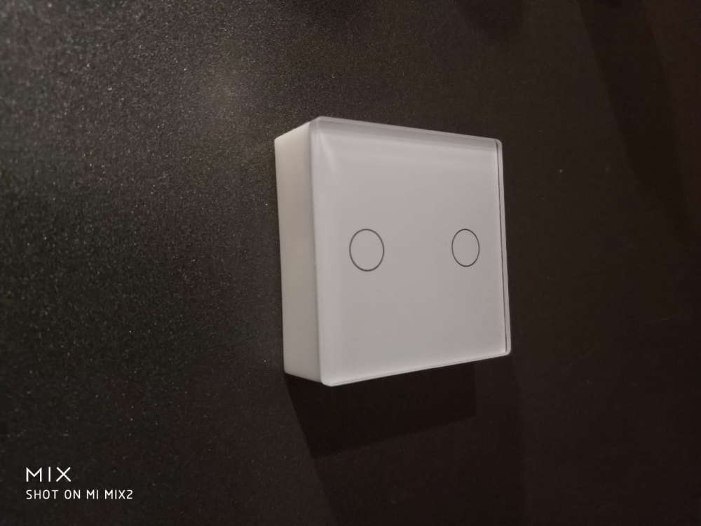
@petewill said in What did you build today (Pictures) ?:
@berkseo nice! What did you use for the capacitive sensor? MPR121?
TTP223s in top left and top right corners ;)
@berkseo I'm curious about that, why not use the capacitive touch function of the NRF52832 ?
-
@petewill said in What did you build today (Pictures) ?:
@berkseo nice! What did you use for the capacitive sensor? MPR121?
TTP223s in top left and top right corners ;)
@berkseo I'm curious about that, why not use the capacitive touch function of the NRF52832 ?
@nca78 said in What did you build today (Pictures) ?:
I'm curious about that, why not use the capacitive touch function of the NRF52832 ?
Ttp223 chips suit me. Very stable stuff. When I tried to do it on amtel328, these mcu also had this feature (almost all mcu have this feature). But it was not very stable. I'm not sure that a stable device using the mcu 52832 would be possible. If there is an example of a stable software implementation, I would be happy to test it, and then it would be clear to do it without external capacitive chips or not.
-
@mfalkvidd good job
-
Built a 1284(p) into a 328p Pro Mini footprint. Not sure what to call it, a Pro Mini XL maybe?
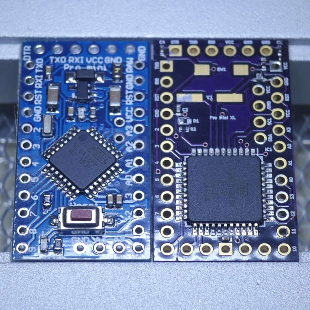
I now have x4 the program memory (128K vs. 32K), x4 the EEPROM (4K vs. 1K) and x8 the SRAM (16K vs. 2K) all in a 328p Pro Mini pin-compatible (I think!) footprint of about same size.
I can also run at 20MHz vs. the usual 8MHz provided I’m prepared to run it at 4.5v and above.
Had to sacrifice a few pins and components, but might be able to put various selections back in future revisions. Nothing major (in my opinion) just components associated with the regulator really. I also went for a crystal (not installed yet, on order, LEDs too..) over a resonator - just a personal preference for when timing is critical.
And yes, those are 0402 SMDs. I actually did them by hand (!) with a microscope and a judicious amount of coffee; a fine-point iron, solder wick and flux became my best friends.
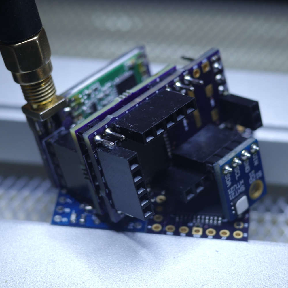
So far, I’ve had it working with nRF24s and RFM69s radios, ATSHA for personalization and external flash for FOTA. The DualOptiboot bootloader code and makefile needed a bit of tweaking, but nothing major.
I broke out the JTAG I/F but haven’t played with that yet and also added power pins next to the I2C to make some of the sensor modules (like SI7021) pluggable - see below.
I also want to play with the QTouch library support for built-in capacitive touch buttons, sliders, etc.
Why not just go with an ARM (STM32, SAMD, nRF52)?
I’m working on it! ;o)
Am not wanting to start a(nother) 8-bit vs. 32-bit discussion. I’ve got an AliExpress package of 32-bit MCUs coming (very) slowly to me. When it arrives, I’ll start experimenting and exploring - probably with the nRF52s, since those seem to be the flavor-of-the-month and very capable-looking chips...
But until then, I need more program memory!
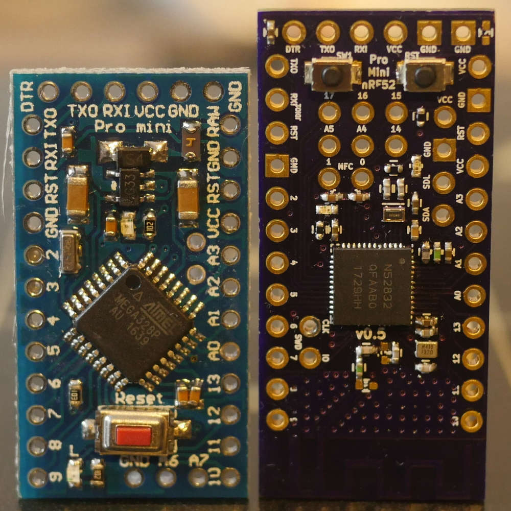
(Among other things…)Continuing along the theme of one of my last projects, I built a nRF52832 into a 328p Pro Mini footprint. Made two versions: One with some edge SMA or U.Fl pads and another with a PCB trace antenna:
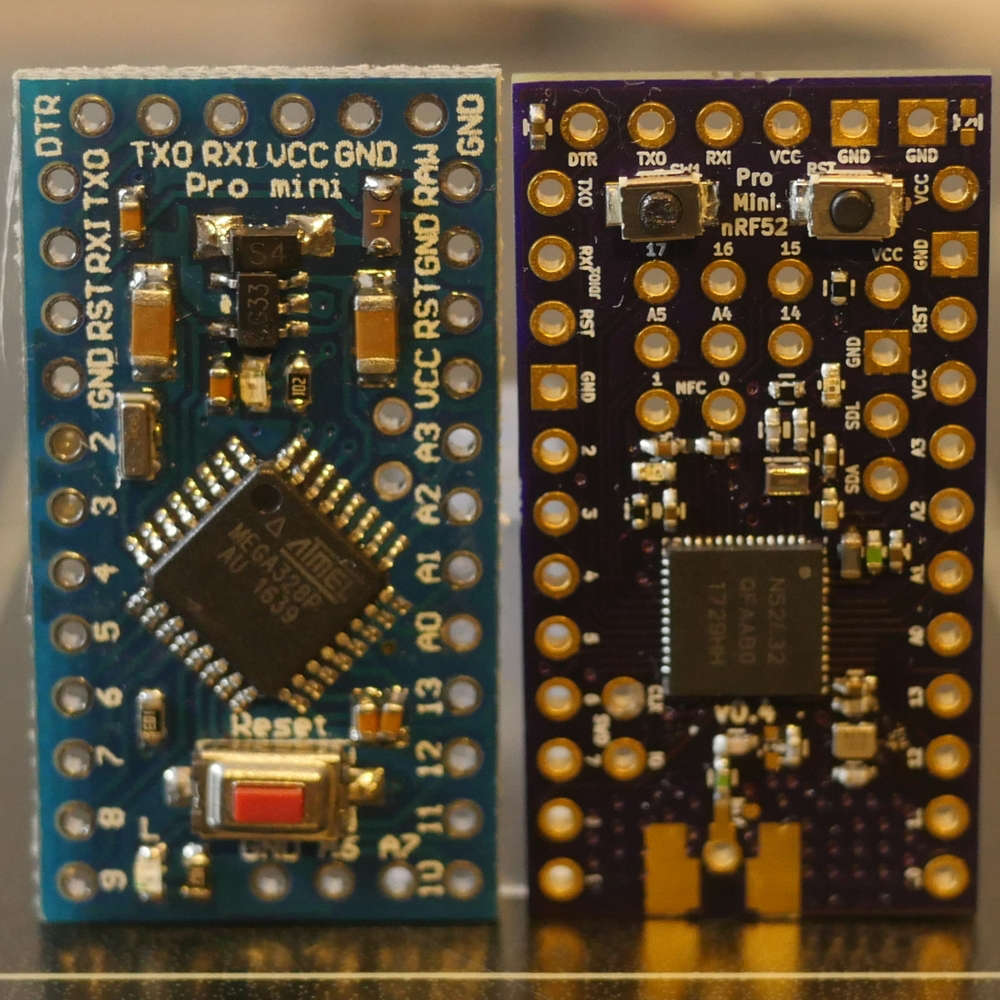
I wanted to start getting into using 32-bit microcontrollers (ARM Cortex varieties like nRF5x, SAMDs, STMs, etc.) for some more complex HA and other electronics projects and am trying to ease the learning curve from all my 8-bit ATMEGA experience.
Keeping the 328p pin-compatible footprint and PCB size means I can still reuse most of my other Pro Mini project boards to get going. An added bonus is the nRF52's ability to remap (almost) any pins, which will no doubt come in handy.
They’re both two layer boards and I get pretty decent range out of the PCB trace antenna - ever so slightly better RSSI than EByte’s E73-2G4M04S1B, which was surprising since I didn’t really do anything different (that I’m aware of) and their module is shielded too.
Since there’s no need for a separate nRF24 board and other associated components, like external SRAM or ATSHA, it’ll possibly save me a few $ too! Power pins next to the (remappable) I2C pins make some of the sensor modules (like SI7021) pluggable.
I also gain 16x the program memory (512K vs. 32K) and 8x the speed (64MHz vs. 8MHz) which is no small increment!
Some of the project boards I have made use of the Pro Mini 328p’s FTDI pins, so I added a few components to enable the use of an FTDI programmer with custom DFU serial bootloader.
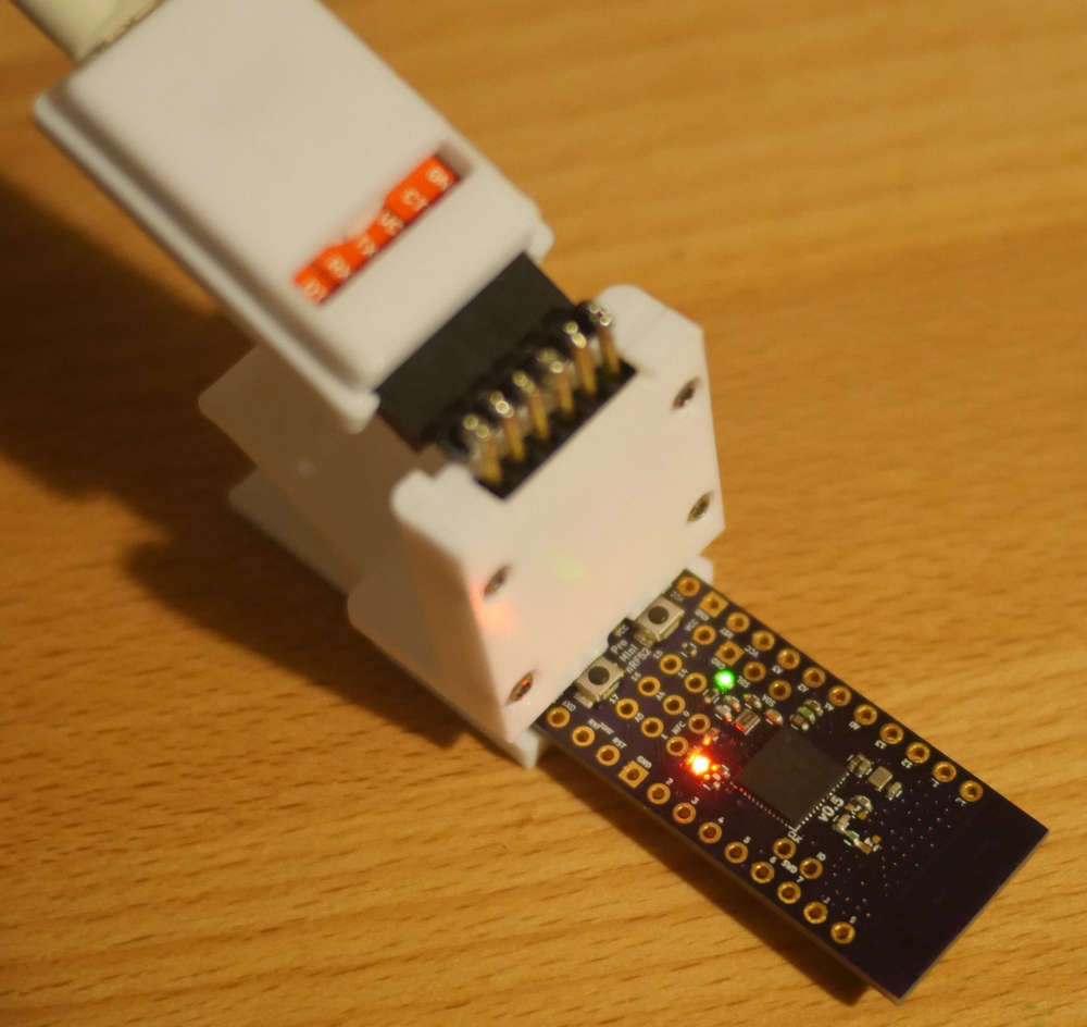
Basically, a DTR pin toggle from the FTDI will reset the nRF52 into a state where it’ll briefly listen for a new program - similar to Adafruit’s Feather. You can also force that state for a longer period with a combination button press like Nordic and SparkFun’s development boards.
I’m unfamiliar with SWD/JTAG programming/debugging and all things GDB/OCD, so I built myself a black magic probe out of a STM32 blue pill and am going to have a play with all of that, along with VS Code and PlatformIO and probably one or two others.
MySensors nRF52 support worked out of the box (!) - so a huge thanks to all the hard work of the folks round here for getting that up and running. If there’s anything I can help with there, please let me know and if I’m able, I’ll try to take a stab at it (OTA maybe?). Like I said, I’ve got quite a steep learning curve here though.
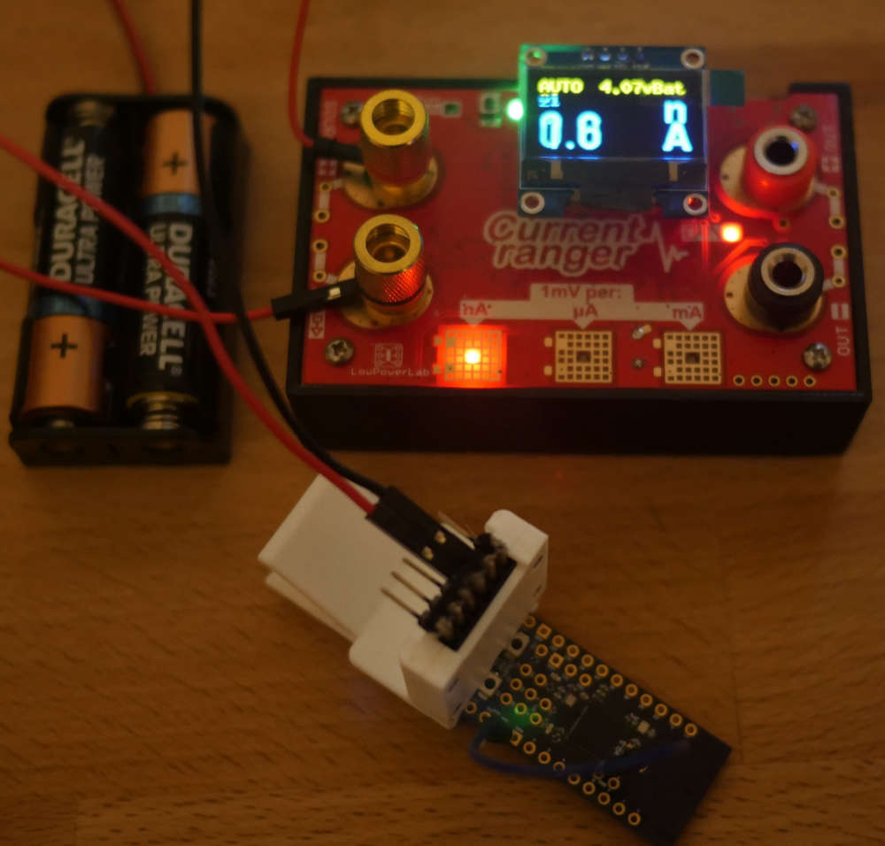
On the low power end, I added the DCDC components Nordic recommend too and managed to get the MySensors smartSleep() current down to around 0.7uA - as per the datasheet, I think. However, I found that with a couple more code tweaks and grounding the SWDCLK, I would get into the nA region. This seems a bit out of spec to me and perhaps it’s just a measuring error, but it was repeatable and the board still happily sending data/heartbeat again each time it woke up. (It’s fluctuating around 1.6nA below - no sensors connected though, but it’s a start…)
One other project in the back of my mind is using this board as the basis for a quadcopter, but that’ll probably have to wait until the summer holidays…!
-
Continuing along the theme of one of my last projects, I built a nRF52832 into a 328p Pro Mini footprint. Made two versions: One with some edge SMA or U.Fl pads and another with a PCB trace antenna:
I wanted to start getting into using 32-bit microcontrollers (ARM Cortex varieties like nRF5x, SAMDs, STMs, etc.) for some more complex HA and other electronics projects and am trying to ease the learning curve from all my 8-bit ATMEGA experience.
Keeping the 328p pin-compatible footprint and PCB size means I can still reuse most of my other Pro Mini project boards to get going. An added bonus is the nRF52's ability to remap (almost) any pins, which will no doubt come in handy.
They’re both two layer boards and I get pretty decent range out of the PCB trace antenna - ever so slightly better RSSI than EByte’s E73-2G4M04S1B, which was surprising since I didn’t really do anything different (that I’m aware of) and their module is shielded too.
Since there’s no need for a separate nRF24 board and other associated components, like external SRAM or ATSHA, it’ll possibly save me a few $ too! Power pins next to the (remappable) I2C pins make some of the sensor modules (like SI7021) pluggable.
I also gain 16x the program memory (512K vs. 32K) and 8x the speed (64MHz vs. 8MHz) which is no small increment!
Some of the project boards I have made use of the Pro Mini 328p’s FTDI pins, so I added a few components to enable the use of an FTDI programmer with custom DFU serial bootloader.
Basically, a DTR pin toggle from the FTDI will reset the nRF52 into a state where it’ll briefly listen for a new program - similar to Adafruit’s Feather. You can also force that state for a longer period with a combination button press like Nordic and SparkFun’s development boards.
I’m unfamiliar with SWD/JTAG programming/debugging and all things GDB/OCD, so I built myself a black magic probe out of a STM32 blue pill and am going to have a play with all of that, along with VS Code and PlatformIO and probably one or two others.
MySensors nRF52 support worked out of the box (!) - so a huge thanks to all the hard work of the folks round here for getting that up and running. If there’s anything I can help with there, please let me know and if I’m able, I’ll try to take a stab at it (OTA maybe?). Like I said, I’ve got quite a steep learning curve here though.
On the low power end, I added the DCDC components Nordic recommend too and managed to get the MySensors smartSleep() current down to around 0.7uA - as per the datasheet, I think. However, I found that with a couple more code tweaks and grounding the SWDCLK, I would get into the nA region. This seems a bit out of spec to me and perhaps it’s just a measuring error, but it was repeatable and the board still happily sending data/heartbeat again each time it woke up. (It’s fluctuating around 1.6nA below - no sensors connected though, but it’s a start…)
One other project in the back of my mind is using this board as the basis for a quadcopter, but that’ll probably have to wait until the summer holidays…!
-
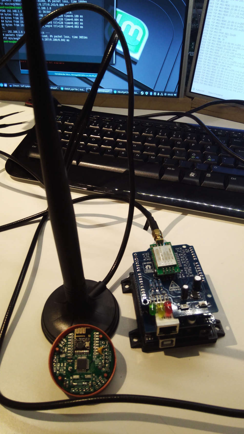
Well,in my case, I mounted and tried to fix bugs in my very first design. This is supposed to be a castelizable Sensebender compatible node, embedding NRF24L01+, LED, Temp/Humi/Press sensor, Memory, crypto, with most of the IO exposed. The updated design is online, but still work in progress.
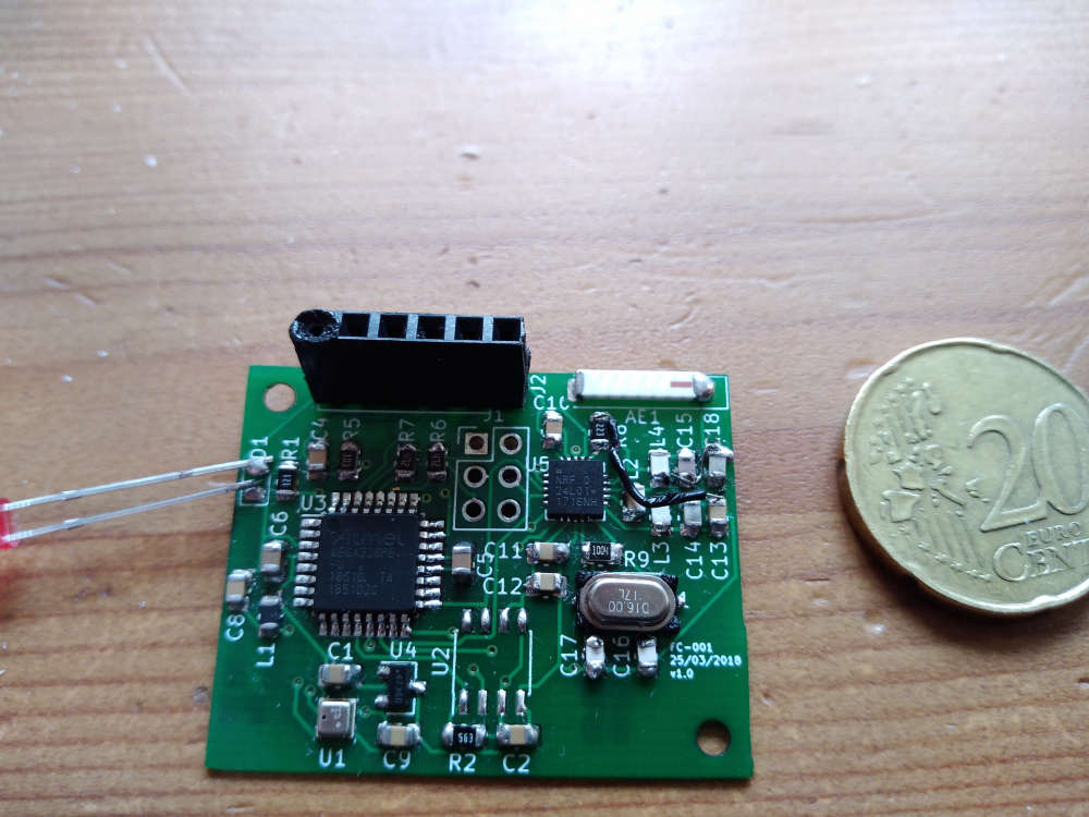
project on OpenHardware -
Continuing along the theme of one of my last projects, I built a nRF52832 into a 328p Pro Mini footprint. Made two versions: One with some edge SMA or U.Fl pads and another with a PCB trace antenna:
I wanted to start getting into using 32-bit microcontrollers (ARM Cortex varieties like nRF5x, SAMDs, STMs, etc.) for some more complex HA and other electronics projects and am trying to ease the learning curve from all my 8-bit ATMEGA experience.
Keeping the 328p pin-compatible footprint and PCB size means I can still reuse most of my other Pro Mini project boards to get going. An added bonus is the nRF52's ability to remap (almost) any pins, which will no doubt come in handy.
They’re both two layer boards and I get pretty decent range out of the PCB trace antenna - ever so slightly better RSSI than EByte’s E73-2G4M04S1B, which was surprising since I didn’t really do anything different (that I’m aware of) and their module is shielded too.
Since there’s no need for a separate nRF24 board and other associated components, like external SRAM or ATSHA, it’ll possibly save me a few $ too! Power pins next to the (remappable) I2C pins make some of the sensor modules (like SI7021) pluggable.
I also gain 16x the program memory (512K vs. 32K) and 8x the speed (64MHz vs. 8MHz) which is no small increment!
Some of the project boards I have made use of the Pro Mini 328p’s FTDI pins, so I added a few components to enable the use of an FTDI programmer with custom DFU serial bootloader.
Basically, a DTR pin toggle from the FTDI will reset the nRF52 into a state where it’ll briefly listen for a new program - similar to Adafruit’s Feather. You can also force that state for a longer period with a combination button press like Nordic and SparkFun’s development boards.
I’m unfamiliar with SWD/JTAG programming/debugging and all things GDB/OCD, so I built myself a black magic probe out of a STM32 blue pill and am going to have a play with all of that, along with VS Code and PlatformIO and probably one or two others.
MySensors nRF52 support worked out of the box (!) - so a huge thanks to all the hard work of the folks round here for getting that up and running. If there’s anything I can help with there, please let me know and if I’m able, I’ll try to take a stab at it (OTA maybe?). Like I said, I’ve got quite a steep learning curve here though.
On the low power end, I added the DCDC components Nordic recommend too and managed to get the MySensors smartSleep() current down to around 0.7uA - as per the datasheet, I think. However, I found that with a couple more code tweaks and grounding the SWDCLK, I would get into the nA region. This seems a bit out of spec to me and perhaps it’s just a measuring error, but it was repeatable and the board still happily sending data/heartbeat again each time it woke up. (It’s fluctuating around 1.6nA below - no sensors connected though, but it’s a start…)
One other project in the back of my mind is using this board as the basis for a quadcopter, but that’ll probably have to wait until the summer holidays…!
-
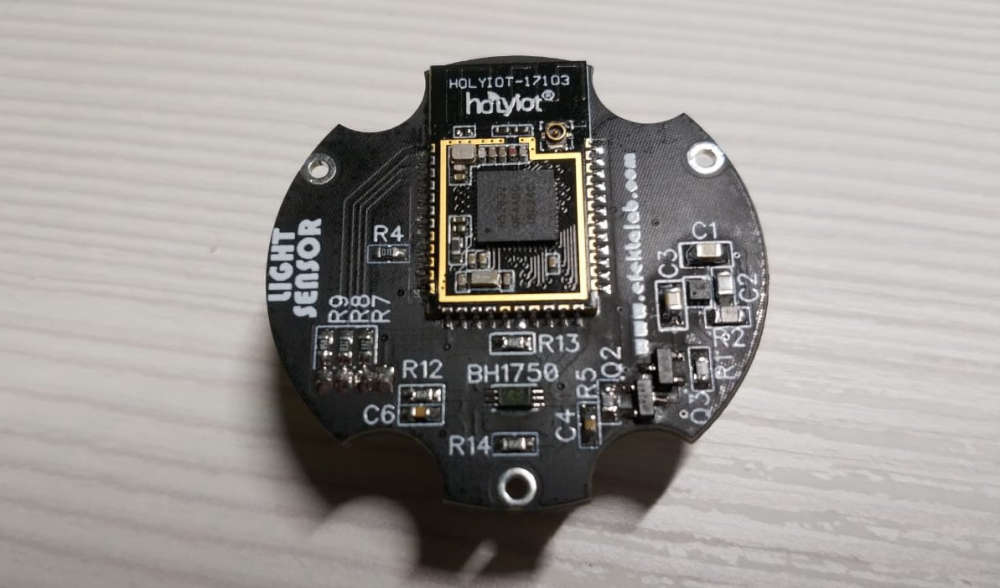
My light sensor on the window. Will work as a slave device for the curtain controller.
-
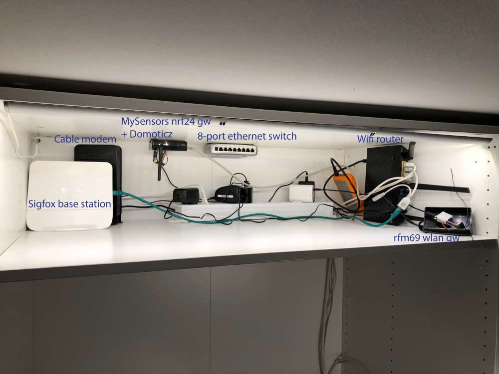
New gateway going live and migrating slowly from Domoticz to Homeassistant. At least to try it.