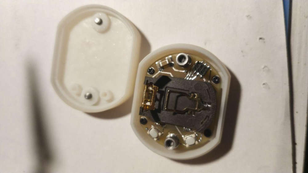
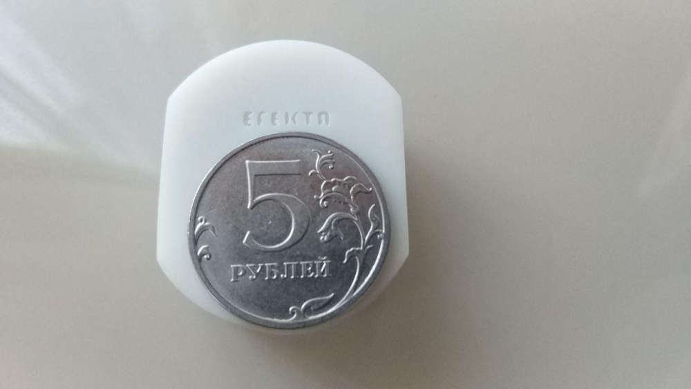
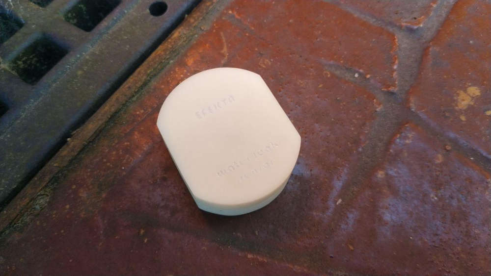
What did you build today (Pictures) ?
-
Thanks @berkseo!
Have been enjoying your work with nRF52 designs.
Also on my list is trying the built-in capacitive touch capabilities of the chip.
I can @ you if I get anywhere with it - might come in handy for your capacitive touch glass mini switch to save you a few components?
-
@acb Of course!!!, ttp 223 gives a reliable result, but if there is an opportunity to make a stable implementation based on the chip itself, then definitely it needs to be done. I would appreciate any help and advice.
-
@acb we can continue discussion in this thread, If you want: https://forum.mysensors.org/topic/6961/nrf5-action/
So as I understand for now you are using native SDK and not using Arduino and mysensors? As far as I know arduino's core for nrf5 has no support for bootloaders, and mysensors conflicts even with softdevice being present on a chip. And it seems that sandeepmistry (author of the core) isn't going to invest his time into writing bootloader and can't use nordic's one because of license. I would like to have a bootloader solely for bluetooth OTA programming for projects beside mysensors. Maybe you could share your work, and/or write some kind of brief tutorial on where to start working on this subject maybe to avoid problems you have already solved? Anyway, great work from you, hope someday we will have mysensors on nrf52 with working OTA.
-
well this is my project , right now im using 2 arduino nano with ethernet shield to read 3 lines Voltage on a delta instalation , 3 current sensors of 300amps for a motor , and 1 water pressure ,
all conected to a raspberry pi with domoticz
but yesterday i decide to change all , instead of 2 uno i will use a pro mini with a nrf24
so i desing two pcb
some code
#define MY_NODE_ID 100 #define MY_DEBUG #define MY_RADIO_NRF24 #include <SPI.h> #include <MySensors.h> #define CHILD_ID_VOLT_1 1 #define CHILD_ID_VOLT_2 2 #define CHILD_ID_VOLT_3 3 #define CHILD_ID_CURRENT_1 4 #define CHILD_ID_CURRENT_2 5 #define CHILD_ID_CURRENT_3 6 #define CHILD_ID_PRESION 7 #define VOLT_SENSOR_ANALOG_PIN_1 0 #define VOLT_SENSOR_ANALOG_PIN_2 1 #define VOLT_SENSOR_ANALOG_PIN_3 2 #define CURRENT_SENSOR_ANALOG_PIN_1 3 #define CURRENT_SENSOR_ANALOG_PIN_2 4 #define CURRENT_SENSOR_ANALOG_PIN_3 5 #define PressPin A6 unsigned long SLEEP_TIME = 20000; // Sleep time between reads (in milliseconds) MyMessage msg(CHILD_ID_VOLT_1, V_VOLTAGE); MyMessage msg2(CHILD_ID_VOLT_2, V_VOLTAGE); MyMessage msg3(CHILD_ID_VOLT_3, V_VOLTAGE); MyMessage msg4(CHILD_ID_CURRENT_1, V_CURRENT); MyMessage msg5(CHILD_ID_CURRENT_2, V_CURRENT); MyMessage msg6(CHILD_ID_CURRENT_3, V_CURRENT); MyMessage pressureMsg(CHILD_ID_PRESION, V_PRESSURE); float lastVolt1; float lastVolt2; float lastVolt3; float lastCurrent1; float lastCurrent2; float lastCurrent3; float lastPresion; int pressure = 0; float PSI = 0; float PSI_CAL = 2.0; // Calibration of sensor int PSImsb = 0; int PSIr = 0; void before() { } void presentation() { sendSketchInfo("Multisensor", "1.7"); // Send the sketch version information to the gateway and Controller present(CHILD_ID_VOLT_1, S_MULTIMETER); // Register this device as power sensor present(CHILD_ID_VOLT_2, S_MULTIMETER); // Register this device as power sensor present(CHILD_ID_VOLT_3, S_MULTIMETER); // Register this device as power sensor present(CHILD_ID_CURRENT_1, S_MULTIMETER); // Register this device as power sensor present(CHILD_ID_CURRENT_2, S_MULTIMETER); // Register this device as power sensor present(CHILD_ID_CURRENT_3, S_MULTIMETER); // Register this device as power sensor present(CHILD_ID_PRESION, S_WATER); // Register this device as power sensor } void setup() { } void loop() { int Voltaje1 = analogRead(A0); int Voltaje2 = analogRead(A1); int Voltaje3 = analogRead(A2); int Corriente1 = analogRead(A3); int Corriente2 = analogRead(A4); int Corriente3 = analogRead(A5); float VoltLevel1 = map(Voltaje1,0,1023,0,500); float VoltLevel2 = map(Voltaje2,0,1023,0,500); float VoltLevel3 = map(Voltaje3,0,1023,0,500); float CorrienteLevel1 = map(Corriente1,0,1023,0,200); float CorrienteLevel2 = map(Corriente2,0,1023,0,200); float CorrienteLevel3 = map(Corriente3,0,1023,0,200); Serial.print("Voltaje L1: "); Serial.println(VoltLevel1); Serial.print("Voltaje L2: "); Serial.println(VoltLevel2); Serial.print("Voltaje L3: "); Serial.println(VoltLevel3); Serial.print("Corriente L1: "); Serial.println(CorrienteLevel1); Serial.print("Corriente L2: "); Serial.println(CorrienteLevel2); Serial.print("Corriente L3: "); Serial.println(CorrienteLevel3); //sensor de voltaje if (VoltLevel1 != lastVolt1) { send(msg.set(VoltLevel1, 1)); lastVolt1 = VoltLevel1; } if (VoltLevel2 != lastVolt2) { send(msg2.set(VoltLevel2, 1)); lastVolt2 = VoltLevel2; } if (VoltLevel3 != lastVolt3) { send(msg3.set(VoltLevel3, 1)); lastVolt3 = VoltLevel3; } //sensor de corriente if (CorrienteLevel1 != lastCurrent1) { send(msg4.set(CorrienteLevel1, 1)); lastCurrent1 = CorrienteLevel1; } if (CorrienteLevel2 != lastCurrent2) { send(msg5.set(CorrienteLevel2, 1)); lastCurrent2 = CorrienteLevel2; } if (CorrienteLevel3 != lastCurrent3) { send(msg6.set(CorrienteLevel3, 1)); lastCurrent3 = CorrienteLevel3; } /* ************************************************ */ pressure = analogRead (PressPin) ; // junk read wait(25); /* • Output: 0.5V – 4.5V linear voltage output. 0 psi outputs 0.5V, 50 psi outputs 2.5V, 100 psi outputs 4.5V 0 psi = .33v after scalling 5.0v to 3.3v 50 psi = 1.65v 100 psi = 2.97v 3.3v/1024 = .0032266 volt per bit */ pressure = analogRead (PressPin) ; if (pressure < 106) pressure = 106; // this is minimum of .5v PSI = (pressure - 106 ) * .1246; // where did we get this?? was .119904 PSI = PSI + PSI_CAL; // adjustment PSImsb = PSI * 100; PSIr = PSImsb % 100; send(pressureMsg.set(PSI, 2)); // Send water pressure to gateway Serial.print("Presion: "); Serial.println(PSI); wait(200); // end of if (SLEEP_MODE || (cu sleep(SLEEP_TIME); }
havent tested with sensors yet
but looks good so far
-
Today, the first sensors of the devices were soldered, the prototypes of which passed long-time tests. Eliminated children's sores. In matt black they are good
-
@berkseo whoa, time for a Kickstarter! They look great! Where did you have them made, and what do they cost?
@fernando-alvarez-buylla Always nice to see the Aurora theme being used
-
And a few days later my pcb's arrived
Now to test the next version
-
Hacking Redmond smart bulb socket RSP-202S
Mysensors | Hacking Redmond smart bulb socket RSP-202S – 02:42
— Andrew EfektaSBon nRF51822...
-
How did you 'hack' it? All I see in the video is you changing a power wire?
-
@alowhum I replaced the manufacturer's software with my own.
The device now works on the mysensors network
-
@berkseo very cool! How did you do that? Did you just have to connect the serial holes to an ST_LINK adapter or something similar? Was is difficult to open the device? And, most importantly: is your code available somewhere?
-
Hacking Redmond SkyPlug RSP-100S
Mysensors | Hacking Redmond SkyPlug RSP-100S – 06:14
— Andrew EfektaSB
-
@alowhum Kickstarter? I'm not sure it's time ..The cost of components is approximately $10. PCB made in China, soldered by myself.
-
@alowhum Soon I will publish codes and the description of process of dismantling and a firmware. But getting ahead.. it's very simple
-
Added two other (e)co2 sensors to my test-setup.
Now 3 NDIR and 2 VOC under observation.
-
A family member gave me an old lamp with a fancy glass base. Well, I didn't like the lamp, but the base was nice, so I kept it in my basement for a few years. I found it again the other day and decided it needed to become a new type of lamp. I put a 150 LED strip (WS2812B) inside. I have an STM32 Blue Bill and RFM69HCW to run the light patterns and connect to MySensors.
In Domoticz, I have it set up as a dimmer light, but the node just switches patterns depending on what the dimmer level is.
At first, I wrapped the LED strip carefully around a tube that sits in the center of the glass jar, but it didn't look very good. Somehow just spiraling the strip in the bottom of the lamp has a much better effect.
My wife even liked it, so maybe I will put some finishing touches on it and actually use it as a lamp : )
-
@berkseo
https://translate.google.ru/translate?hl=&sl=ru&tl=en&u=https%3A%2F%2Fmysku.ru%2Fblog%2Fdiy%2F72557.htmlOriginal (code without Google formatting): https://mysku.ru/blog/diy/72557.html
-
Test nRF52840 with Mysensors on Arduino IDE
Mysensors & nRF52840 on Arduino IDE – 01:19
— Andrew EfektaSBbased on source - https://translate.google.ru/translate?sl=ru&tl=en&u=https%3A%2F%2Fmysensors-rus.github.io%2Fnrf52840-The-first-steps%2F
-
Well, Design of an home made electronic kit for my 10yo daughter to teach her by example. on 74HC595 (shift reg), 9 leds, 4 push buttons, some wrapping wire, ... We managed to build it, it works, with some bad contacts, but it works, she enjoyed the thing and the time spent together. Here is the schema and the pictures. I strongly invite parents to build it with their children, easy and fun. !
-
@fanfan
Looks nice, and I love the idea that you spend time and knowledge to your kids
but looking at the current budget it seems that you are above the rated current consumption for the 74HC595, just so you don't wonder in case it burns when several LEDs are ON at the same timeInput clamp current, I IK (V I < 0 or V I > V CC ) ±20 mA
Output clamp current, I OK (V O < 0 or V O > V CC ) ±20 mA
Continuous output current, I O (V O = 0 to V CC ) ±35 mA
Continuous current through V CC or GND ±70 mAData from here:
https://www.sparkfun.com/datasheets/IC/SN74HC595.pdf
-
@berkseo
https://translate.yandex.ru/translate?url=https%3A%2F%2Fhabr.com%2Fru%2Fpost%2F450860%2F&lang=ru-en
-
@dbemowsk I've been gambling with an Adafruit AudioFX board and cobbled together this annunciator. Eventually it will likely be a MySensors node to play alarms or different sounds. It is using a reasonably-priced transportable speaker to play the sounds. I were given it to work with my doorbell button node today.
-
Prototyping my netatmo replacement device. It has an led strip that can simulate a lighouse, a rainbow or a fireplace...
(If not used only for fun, it should warn you, if there is too much CO2 in the air.)
-
Today I have spent a few hours trying to eradicate the confusion between MySensors' different message acknowledgements. See https://github.com/mysensors/MySensors/issues/1103 and https://forum.mysensors.org/post/34263 for details.
core/MyGatewayTransport.cpp | 11 ++++++----- core/MyMessage.cpp | 8 +++++++- core/MyMessage.h | 31 ++++++++++++++++++------------ core/MyOTALogging.cpp | 2 +- core/MyProtocol.cpp | 16 ++++++++-------- core/MySensorsCore.cpp | 41 ++++++++++++++++++++------------------- core/MySensorsCore.h | 114 ++++++++++++++++++++++++++++++++++++++++++++++++++++++++++++++++++------------------------------------------- core/MySigning.cpp | 4 ++-- core/MySigning.h | 2 +- core/MyTransport.cpp | 20 +++++++++---------- core/MyTransport.h | 4 ++-- examples/SecureActuator/SecureActuator.ino | 2 +- 12 files changed, 147 insertions(+), 108 deletions(-)
I have also updated https://www.mysensors.org/download/sensor_api_20 to use echo instead of ack when describing the echo function. That page didn't have information on the return value for send, present, reqestTime, etc so I added info on the return value as well.
-
When doing the change above, i noticed that after I created https://github.com/mysensors/MySensors/issues/1107 the number of undocumented MySensors keywords has more than doubled!
The plan was to let the MySensors butler check for missing keywords as soon as the few remaining keywords were documented. If I add the check on the existing code, the butler wouldn't allow any commits which would hinder development. But since no-one has documented the missing keywords in over a year, I decided to blacklist the missing keywords and add the check anyway. The new check will give developers a list of new missing keywords, if they add any, so they can be documented.
-
I've also submitted documentation updates for clarifying MY_RX_MESSAGE_BUFFER_FEATURE limitiation on esp8266 and renaming RadioSetting to TransportSetting for https://www.mysensors.org/apidocs/group__RadioSettingGrpPub.html
References:
https://github.com/mysensors/MySensors/pull/1296
https://github.com/mysensors/MySensors/pull/1295
-
Today I have finished my d-diot board:
The board is part of the d-diot project (see my other post)
-
My 3V Node (Atmega328P 1MHz), embedded NRF24L01+ with ceramic antenna, ATSHA256, AT25DF512, BME208, LED, Battery monitoring, ICSP, FTDI, Castelizable, Breadboardable.
-
@fanfan nice! How is the signal compared to stock nrf24 modules? How much for antenna?
-
@monte A little bit less, but not a lot. I still need to improve the PCB (better castelization tracks, remove diodes, ...) and this should be ready to be copied/used.
-
Today finished with the HW part of the new device
hw test e-ink2.7+ccs811+sht20 on nrf52832 – 00:21
— Andrew EfektaSB
-
@mfalkvidd
Looks impressive!
-
Today finished new device:
Video:
Wireless Touch Switch (nRF52832) (CR2450) with fluorescent – 02:21
— Andrew EfektaSB
-
Today.... This MQ2 gas sensor with Neopixel RGB lamp on top and a capacitive touch button under the circle mark on the front.
It is part of the d-diot project. The files of the 3d-printable case are available in Thingiverse.
The firmware is available here, the wiki page is under construction.
In the next weeks I will try to print it in wood... Just to increase the WAF
-
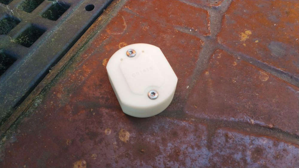
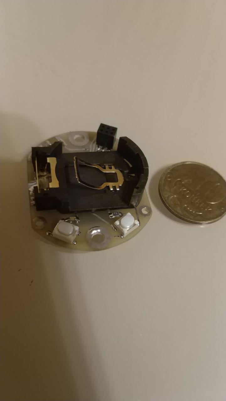
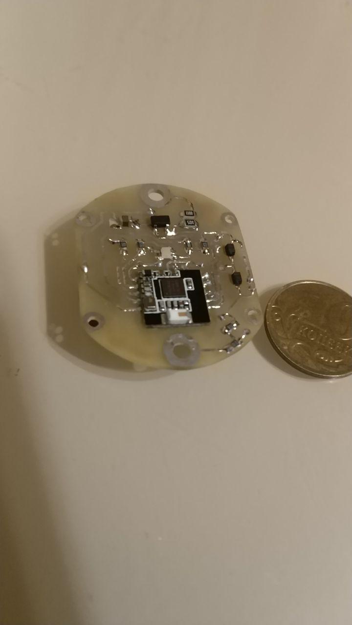
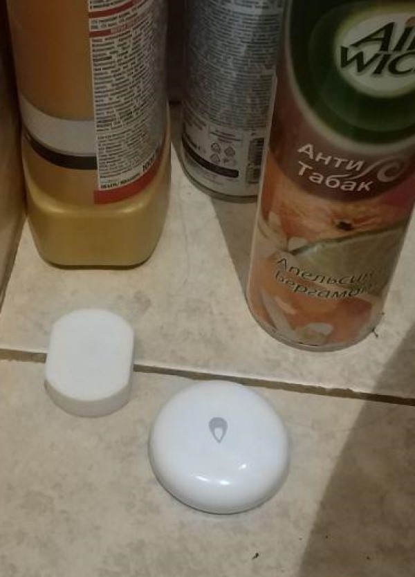
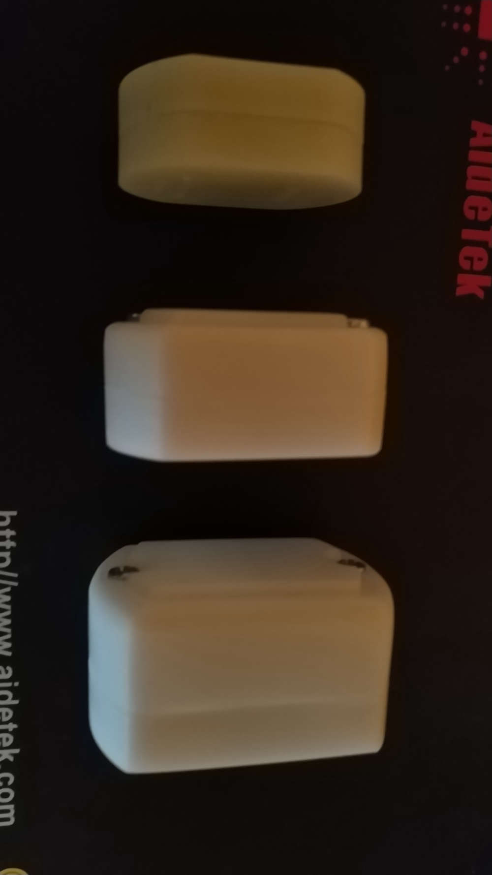
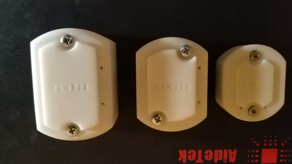
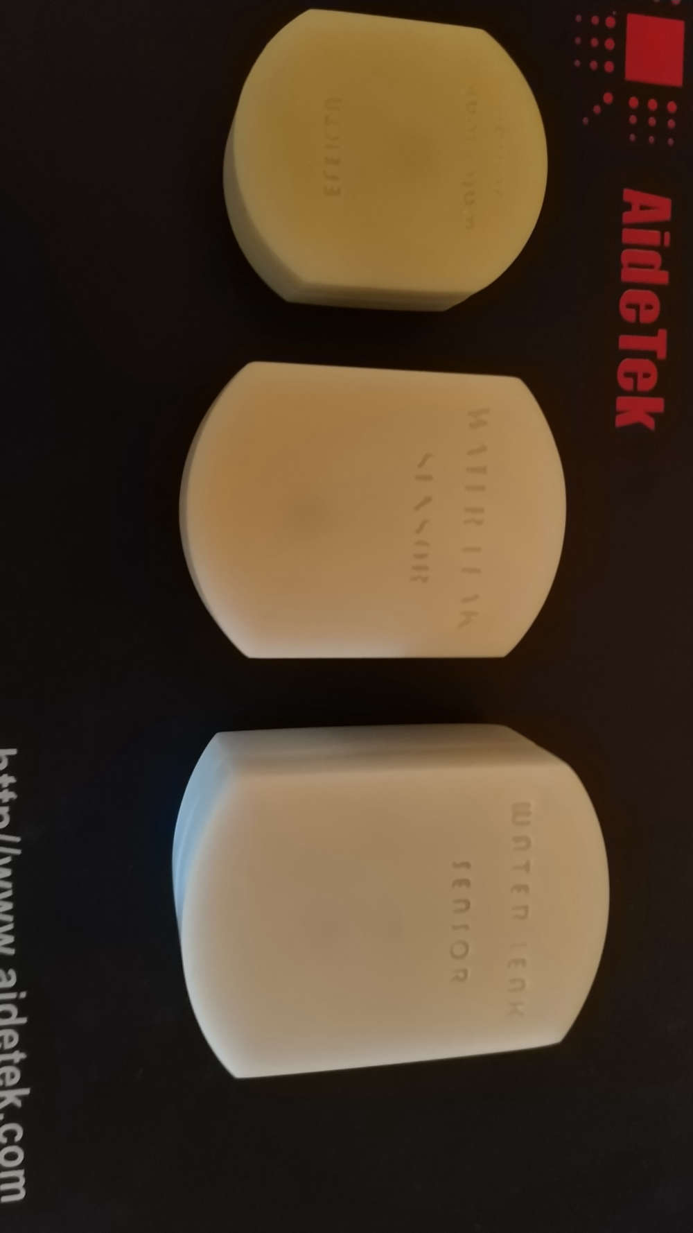
My new micro-sensor water leak ready. Powered by NRF52832-CIAA
cr2032, ... ~3μA consumption
-
Love to to watch all you creative designs
-
Pro version of water leak sensor, for very very hard to reach and remote places :). Version with amplifier.
-
@berkseo what's the range improvement with amplifier ?
From my experience with nrf24 the amplifier + ceramic antenna was not giving great results.
-
@nca78 said in What did you build today (Pictures) ?:
what's the range improvement with amplifier ?
From my experience with nrf24 the amplifier + ceramic antenna was not giving great results.A few months ago, when testing, I received about 200 meters of stabilized power from the power bank. While this device was tested for 30 metres. There are problems with receiving the delivery confirmation, the device is guaranteed to transmit, but does not receive the delivery confirmation(sometimes). I think it's linked to my gateway, it has the usual radio module nrf24l01+. Of course we are talking about dc-dc-mode
-
I do not want to be too offensive, but it seems to me as if your skills in electronics and 3D-printing is way better developed than your trust in the plumbing
Now for the serious part: how often do you experience water leaks? And how long do the batteries in this design last?
Boozz
-
@boozz serious water leak heppened once in 40 years
-
@gohan
I was referring to @berkseo 's situation and images/examples. I just wondered why this person would put this amount of effort in creating a device that would probably not be functional at the moment it should be functional. I'm just thinking about corrosion of the pcb, a drained battery, change of properties of the 'sensor' due to time-effects etc.
Do not misunderstand me: I'm absolutely enthousiastic about this device (and I'm impressed by how small it is and the design), but I'm a bit concerned about the effects that could negatively affect the behaviour of it.
-
@boozz said in What did you build today (Pictures) ?:
@gohan
I was referring to @berkseo 's situation and images/examples. I just wondered why this person would put this amount of effort in creating a device that would probably not be functional at the moment it should be functional. I'm just thinking about corrosion of the pcb, a drained battery, change of properties of the 'sensor' due to time-effects etc.
Do not misunderstand me: I'm absolutely enthousiastic about this device (and I'm impressed by how small it is and the design), but I'm a bit concerned about the effects that could negatively affect the behaviour of it.You can see on the picture he already had a leak under his kitchen sink
And in some countries pipes installations are not very reliable, for example yesterday evening my dishwasher emptied on the floor because the workers did not glue the PVC pipe angle so it went away. Would have love to be warned at the first drops instead of realizing it much later when walking in water in the middle of the kitchen. I also had problem with drinkable water fountain not stopping when tank was full and emptying the 20l bottle on the floor, leaks of sinks and bathtub in the bathrooms in previous apartment, etc etc
So there's truly a "market" for those sensors, they could also be slightly modified to make rain detection instead and warn you if rain is coming and some windows are still opened (very useful here in tropical weather when you can switch from sunny to tropical rain in a mater of minutes).And if you use the low power comparator of the nrf5 it uses only a few uA in sleep mode, easily detects a bit of water between the 2 contacts and can last for 1-2 years on button cell.
-
@nca78 I suspect what @boozz is referring to is not the functionality but the direct effect of water on the device.
Pretty sure a pair of threaded socket bolts could be swapped for the cover screws and permit wall mounting on a couple of threaded SS electrodes to solve it though, and it would still make for a very compact and unobtrusive arrangement.
-
I think very useful device.
Stainless screw like detectors - no corrosion.
And all the time this device sits in dry area - no corrosion.
But software must call controller ( with battery level for example ) sometimes, say one per a day, to inform it is alive.
And if controller does not receive this message - sends alert.
I am using this for all my nodes - very easy in Domoticz.
If node dies, Domoticz send me e-mail ( and SMS ) with information.And 40 years with this hoses for example ?
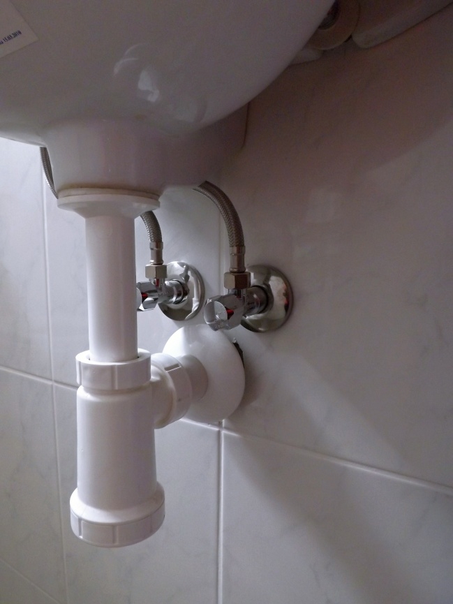
Try it .....
-
@kimot I followed your logic until you suggested 40 years in the future with presumably failed wash hand basin umbillicals..
-
@berkseo I'm sorry if I can, but what kind of sensor are you using to detect water ?? I would like to do something like that but with an Arduino pro !!
-
@boozz A leak of water in my memory occurred two or three times. Yes, this is not a common problem in the modern world. But sometimes it is enough once. And here it is important how this leakage will be quickly detected and, accordingly, the source of water supply will be blocked. And one more thing: insurance can not cover everything. One situation is when it’s a country house, but for example in Moscow I live in an apartment on the 6th floor, that is, there are 5 floors below with apartments, and I may have to pay for repairs in these apartments.
Now I have three sensor options: on a cr2032 battery, on a cr2477 battery, and on a 2 / AA (14250) battery with an amplifier.
The devices consume 3 micro amperes in a dream , on conventional radio modules they consume 7–9 milliamperes while the transmission is running, for modules with an amplifier of 24–26 milliamperes, and I can programmatically decide when I should turn on the amplifier.
-
@boozz It was just a photo session in various locations :).
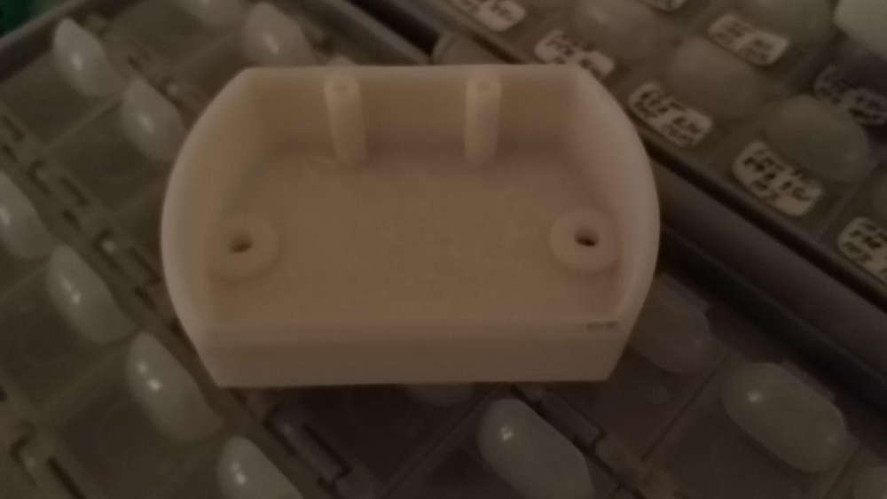
The pcb, of course, will be coated with acrylic varnish. Stainless steel contacts are used. Conclusions do not have direct contact with the ground, there is a gap of about 0.5-1mm. Button holes are made from below, but look at how it is done in the photo. Well and places where leakage is possible, usually should not be wet, otherwise a mold and td. If there is moisture, then it is somehow better to eliminate :).
-
@sindrome73 said in What did you build today (Pictures) ?:
I'm sorry if I can, but what kind of sensor are you using to detect water ?? I would like to do something like that but with an Arduino pro !!
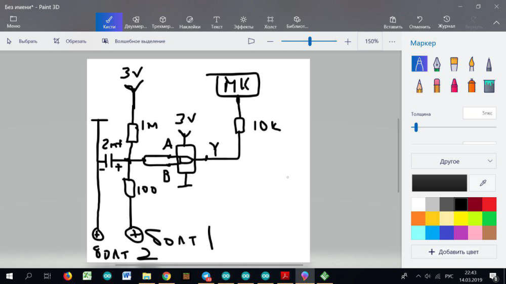
Used by SN74LVC1G00. Recently I was asked for this scheme in myssensor_rus telegram-chat. I drew it by hand in PAINT, I can offer it to you. I apologize, but nevertheless it is a scheme
-
@zboblamont said in What did you build today (Pictures) ?:
umbillicals
It is rubber hoses with metal braiding.
But rubber degrades and this equipment is the most common cause of water leakage.
-
@berkseo thanks for the scheme. but therefore don't use a sensor ?? i'm sorry noni and clear how do you detect the presence of water ...
-
@sindrome73 the sensor is the two screws. Without water, the elevtrical between the screws is very high. With water, the electrical resistance is lower.
-
@mfalkvidd ok now I understand, and then commands an Arduino or other. thank you
-
@kimot The elastomers used are resilient and will last decades from new, never seen one burst yet. Most folks remodel bathrooms every 5-10-20 years and should replace these at the same time, which was why I chuckled at the 40 years.
With the technology and battery longevitity available nowadays, they are certainly a handy device to have where problems have occured or may.
-
@berkseo
Clever idea to use SN74LVC1G00 as while both inputs are same voltage it only consume ICC = 10uA (10 mircoA) in whole voltage range 1.65V -5,5V
-
@bjacobse said in What did you build today (Pictures) ?:
Clever idea to use SN74LVC1G00 as while both inputs are same voltage it only consume ICC = 10uA (10 mircoA) in whole voltage range 1.65V -5,5V
Power consumption of the entire device in a sleep - less than 3 mircoA.
-
@bjacobse said in What did you build today (Pictures) ?:
@berkseo
Clever idea to use SN74LVC1G00 as while both inputs are same voltage it only consume ICC = 10uA (10 mircoA) in whole voltage range 1.65V -5,5VNot when when you have a low power comparator available that runs with only 0.5µA...
-
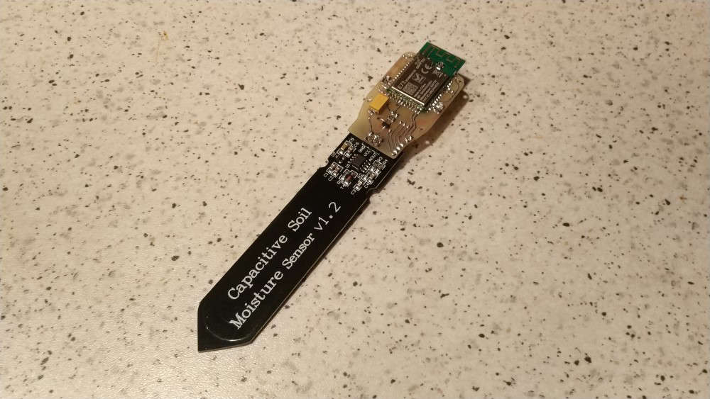
Wireless expansion module for very cheap soil moisture sensor from Aliexpress
MySensors | Wireless Module for Capacitive Soil Moisture Sensor v1.2 – 05:12
— Andrew EfektaSB
-
Finally the round-tuit UPS got built after the last power cut clobbered the Controller/Gateway system, lesson learned...
Meanwell AD-55A, 7.2Ah Acid gel battery, two usb 5v buck converters, a spare socket for raw volts, and a 15 euro IP66 box from the local shops.. Some drilling and filing to the lid, couple of brackets, spare bolts, banding, soldering and hot glue...
A bit bulky, but disappears in a void under the stairs, two tiny drill holes let the buck converter leds shine threw...
No monitoring as yet, but sailed through a power cut this morning and the Pi didn't skip a beat.. First up is the Pi's RTC then can put the cover back on the Controller...
-
@zboblamont is the battery and switch mode psu just in parallel? Or do you have a switchover / charge circuitry?
-
@tbowmo The Meanwell AD-55A is a purpose made 12v UPS type with all controls onboard. There is an optional version with monitoring brought out to a connector block, but I couldn't find one.
The photo angle is misleading - Channel 1 +/- is to load, Channel 2 +/- is trickle charge to battery, power failure switches seamlessly to the battery as source..
It's a fairly comprehensive arrangement with an array of safety features including battery protection, eg - If during power failure you disconnect the battery, it's reconnection will not restore load power, and resets only on mains supply.
Case ventilation made using a metal bracket with a matrix of holes as a drill through template so it looks neat, but as the PSU barely gets warm to the touch it proved to be overkill.
-
@zboblamont Do you have any more info on this? Components and schematic? I am looking to do this as well as Florida is now fully into storm season.
-
@wergeld Sure, but this is where I first read about it as part of a comparative link text when I was trying to decide on a UPS after a series of outages (frequent out here in the sticks).
The dual buck converters were the only real variation (in case one blew). Following kind advice after querying buck converters on this forum, this is the type I ordered but off eBay, but this is very similar layout... link text
I should explain that I would have gone for a commercial UPS had a decent USB supply been quoted, but the reality is that for most the USB is of secondary consideration to backup mains...
I gets interesting when you consider the actual Ah capacity before the battery low cutout operates, I reckon well in excess of 12 hours...
Have fun...
-
not with mysensors, but could have been: CNY70 water sensor meter (rotating wheel) with extended wifi range, the heart of it is a Particle Photon pushing to domoticz
-
Today I finished printing the case. Turned out to node with sensor bme280 and e-ink display, running on nRF52840 from SKYLAB
In one of the photos still have the sensor with bme280 working on nrf52840 from EBYTE. ...This is the previous project.
upd.
-
I have soldered the first sample of "xRoom" board.
TODO: testing and detail description of the project))
-
@kalina That is some excellent solder work. Last time i tried to do SMD work it ended up being 110% solder, 5% PCB, and 0% component at the end.
-
I didn't build this myself, but I did create the code. It's a MySensors CO2 sensor that is part of a 'privacy friendly smart home of the future' which will be launched later this year.
It was made by artist and jeweler Dinie Besems. All her creations feature small 'skirts' that you can lift to see the data, or cover up the screen if you have visitors and don't want them to immediately see your data.
-
Etched and soldered a new gateway after the original one I had failed.
-
Meet Janus project, a premium USB dongle by Tekka and me
Dual RF gateway with external antennas.
- nrf52840 with 20dB PA + SMA connector. So it can be compatible with MySensors, and/or zigbee..
- rfm69hcw/rfm95 long range + SMA connector . module has all DIO pins routed for sw driver optimizations.
- reset button
- user button
- RGB led
- high PSRR RF/analog 700mA LDO
- usb protected
- 4layers board
- enclosure size : 52x21 (thickness 11mm). compact!
Enclosure is just a quick proto, I'll improve quality, or I would like to try online multijet service, I'm curious
It's very recommended, for better performance, to have some distance between antennas.
So, for example, I'll use a shorter antenna (without cable) for 2.4ghz, and a "remote" antenna (with a cable) for 433/868/905Mhz, so it can be used with different kind of antennas.We choosed external antennas, because
- versatile use
- better range especially when dongle is close to lot of stuff which could affect range in case of a pcb antennas
-
@scalz ohh! Where can I order one?
-
Wow @scalz that's a badass gateway dongle, any pictures of the inside ?
Do we have more chances to see that becoming available, than HALO and Aeos ?
-
thx for interests guys
I'm just not sure if there would be enough interest for me to produce. I've not really thought about it! It's the first board of the batch.I call it a premium dongle because
- it's 4layers. It's just a little bit more expensive than 2layers. But quality is a lot increased (better impedance, full gnd plane, better routing etc). It's also recommended by lot of rf module manufacturers for topnotch perf
- I uses the high quality BT840XE module. As you know, it's a well documented and known module, and it's CE/FCC (better, as it includes a 20dB PA).
Actually I just use a few pins on edges, and 18 pads under it..
I had the choice to use this module, or to design mine with a frontend, but for once, I decided to go "simple" for a quick debug. And the price difference vs homemade, maybe +10€, is worth it imho, time saver, and I don't mind I just need one!
Why did I make it? Because I can and would be pity to deprive myself
And we can have a nice and reliable dongle for the team, just in case.You're right I have others hobby projects, they're not dead..
- just lost a bit of interest on Aeos release, I agree on this, because I prefer subghz for mysensors, and would like to keep 2.4 for others protocols.
- Halo is not dead, actually it's one my favorite. I just need to find a way to include Janus in my "serverless" project which is mostly ethernet based (I made a full webapp, that I'm porting to true native crossplatform sw, android phone+tv, windows, linux, for better experience). "serverless" meaning optional rpi/computer
Oki, I'll post others pics soon.
-
This evening I assembled another dongle (and a few other boards).
@nca78 as you asked, here is a pic during tests. Tiny dual rf dongle board, isn't it
-
@scalz How do you plan to use your dongle? Just as coordinator? or only as a gateway mysensors? Have you tried using it as a combo? zigbee quite unceremoniously uses the resources of the mcu.
-
@scalz said in What did you build today (Pictures) ?:
This evening I assembled another dongle (and a few other boards).
@nca78 as you asked, here is a pic during tests. Tiny dual rf dongle board, isn't itThis customization boards adafruit? I've customized the Board Sandeep Mistry.
-
Air particulate sensor.
BTW, solder fumes seem to be bad for you........
-
- like I said, MySensors bridge, combo . Yes I know about resources.
Note: zigbee is out of MySensors scope (not arduino code), so for the moment some ideas and POCs will be local, not making money no ETA, still lot of WIPs and the daily job! - yes.
- like I said, MySensors bridge, combo . Yes I know about resources.
-
Modified a laser filament sensor (pat9125, used with Prusa mk3) to be used with an ESP32.
Maybe I will use it as a filament stuck sensor with octoprint. Or a filament meter?
-
Very first attempt to solder smd components on pcb with hot air soldering station. lots of mistakes but i m learning...
-
First of the winter projects done, just the programming to finish and replacement temperature chips to get (broke the legs off both DS18B20s through clumsiness).
With mains/battery backup and RTC, it will record boiler start/stop and run times as well as feed/return temperatures, and as an aside the inevitable power cuts which plague this part of the world.
The MCU plugs into a socketed backplane hot-glued to the back of the box should removal prove necessary, but quite pleased it is sturdy and all fitted into a slim 25mm deep standard (cheap) box.
-
My brand new device on nRF52840. It is a light and shock(vibration) sensor.
Two sensors are used, max44009 light sensor (1 ua) and lis2dw accelerometer (1 ua).
The light sensor measures in Lux.
The shock sensor has five levels of sensitivity.
Two modes of operation: main (working) mode and command reception mode.
The sensor accepts settings: the interval of sending data from the light sensor (in minutes), sending recalculated light data from Lux to watts per meter squared(on/off), the sensitivity level of the shock sensor(5 levels, 1 to 5)
Depending on which sensors are installed on the PCB, it can be used only as a light sensor, only as a shock sensor or both.
In the near future the project will be posted on openhardware.io
video (inside view of the sensor, an example of working with a smart home, an example of setting): - https://youtu.be/I2ywIxp-RsE
-
@berkseo this would also be good for monitoring when the trash cans get picked up by the garbage truck. If it has enough range that is. Of course that wouldn't apply to high rise dwellers, but for people in houses it would be a nice perk.
-
working on GPIO MySensors Gateway
-
An updated version of my temperature and humidity sensor with e-ink. Now on nRF52840. Now it is not a module but a device in the case.
Replaced temperature sensor sht20 -- > > si7020
Added accelerometer.In the near future the project will be posted updated on the website openhardware.io
Video: https://youtu.be/T66y83lF-xg
-
Amazing!
The case is 3d printable?
-
@franz-unix
This is made on SLA printer, but should normally print on FDM
-
@pihome just realized one big blunder, The NSS, MOSI and SCK are not 5V tolerant on RFM69. hence need level converter
i was wondering is there any one ic can can do instead i have to used BSS138 per pin.
-
@berkseo I'm quite interested in a schematic view showing how the epaper gets wired up, because priced just by itself epaper seems like an affordable solution.
or
On the other hand, if one has to rely on adafruit or similar for an epaper breakout board to make use of it, the effective price jumps by around 5-6x or so.
-
@neverdie you can use this and this as a reference. No need to buy ready breakout board, if you know how to trace your own.
-
https://github.com/dkjonas/Wavin-AHC-9000-mqtt
iron and toner transfer, then etched and soldered and finally acrylic spray on cobber so it won't corrode
-
Hello, as it was getting seriously off topic, I moved the discussion related to SLA printing of enclosure to here :
https://forum.mysensors.org/topic/10815/printing-enclosures-with-sla-printersFeel free to suggest a better title.
-
I've had surprisingly good luck buying cheap parts from Ali-express, but not this time. I bought an NRF52832 iBeacon that supposedly had an SHT30 temperature sensor and KX022 accelerometer. When the parts arrived, neither of those parts were populated. All the beacon has is a push button.
I was able to program it to work with MySensors, however. With only SWIO and SWCLK (no txt out), I took @scalz advice (in another topic) and used a J-Link EDU Mini so I could use the RTT app to get printf style debugging. That worked nicely and I learned a new tool.
Perhaps I can use the iBeacon button for a remote.
-
Yesterday I finished my new project. This is motion sensor (S16-L201D) + light sensor (MAX44009) + temperature and humidity sensor (SI7020). Рowered by nRF52840.
..upd
video - https://youtu.be/cbJYam4jo2g
-
Another 8x8 matrix based display...
This is not a real project, just a try to hide the LEDs for better WAF.
Print still needs some impovements, but from a little distance you can't see the details.
-
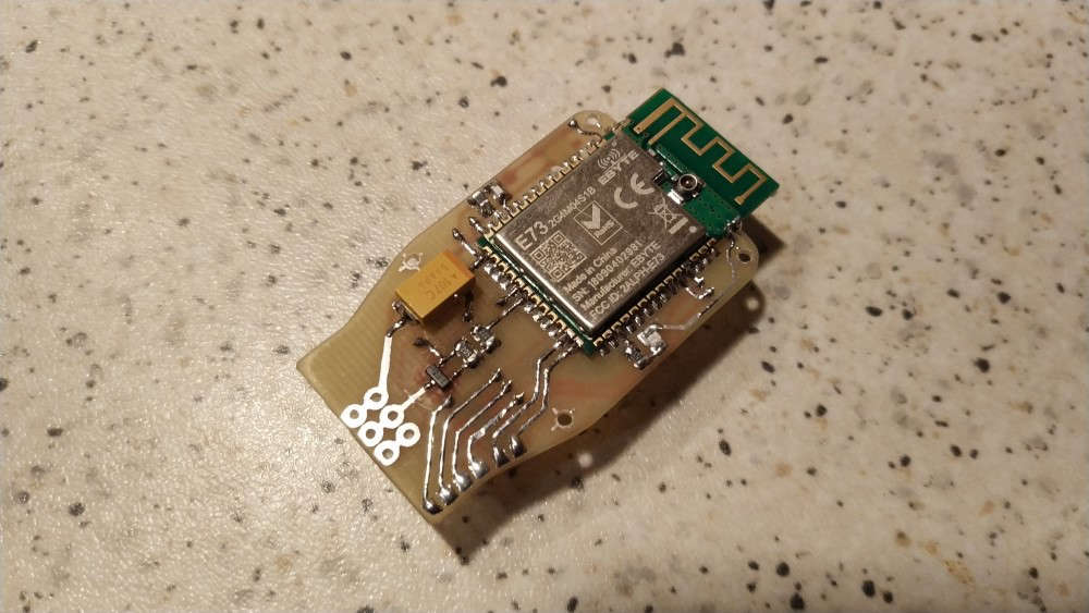
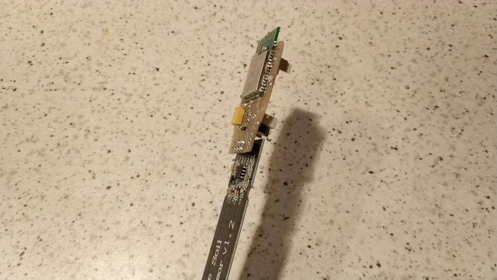
My new project is finished today and put to the tests. This is a continuation of my other project - Wireless Module for Capacitive Soil Moisture Sensor v1.2.
video: https://youtu.be/2HM0y-D7QNo
-
Wow. All these recent creations are so professional. Really nice!
-
Another project of mine, the second revision is finished today and put to the test. This is an encoder with accelerometer, powered by nRF52811 chip (datasheet).
-
@berkseo Cool!