What did you build today (Pictures) ?


  • Hero Member

    @zboblamont Ah, you got bit by my main reason for not liking Domoticz: Domoticz would be so much more useful without that 5 minute minimum between recorded datapoints. It's a wonder they've never fixed that.


  • Hero Member

    @Nca78 Just FYI, I looked into attempting a FOTA on the nRF52 but at the time I didn't feel as though I had enough easy-to-follow information to do it within the limited spare time available. I think adafruit may have some kind of FOTA for the nRF52 with their circuitPython project, but that language's runtime is awfully slow compared to C or FORTH.


  • @NeverDie I don't mind it so much as an overview, it's getting sense of the overview which is the problem as the detail is absent from the graphing.
    Simple enough for my purposes though, sitting in a kitchen with a glass of Rioja recording details is remarkably simpler than spilling a perfectly good wine dashing back and forth balancing a notebook, pen, laser thermometer and a clock..
    We work with the tools we have, which on balance are a lot more advanced than when I was your age when flints, candles and acetylene were all the rage...


  • @NeverDie I came to this idea after I read again about your trying to add FOTA to nrf52. What do you think about it?


  • Hero Member

    @monte I think it may run into the same barrier I encountered with both uPython and FORTH and uLISP. I got them all to do FOTA with nRF52, which is easier because they are interpreted, but in none of the cases could I easily leverage the wonderfully extensive arduino sensor libraries because those are written in C. Apparently there do exist ways to do it with linkers and such, but I wouldn't classify it as easily done. More like "easier said than done." uLISP would have been the easiest to adapt C-libraries, but it's a slow inefficient implementation of LISP, so that was a downside. Although practically anything can be made to work given enough time and effort, there's something to be said for staying within the Arduino framework so as to minimize time and effort.

    That said, maybe your idea is different. Sometimes it's hard to really know until you explore it a bit.


  • @NeverDie I mean, what exactly use scenario for FOTA update of a remote working node? What can you possibly want to change remotely without changing any hardware? I guess it can be some logic, or parameters that may require adjustment that can be made remotely, and that's how I think JSON can be used to specify those. I well may be overlooking the big part of a problem, so I ask to better understand it.


  • Hardware Contributor

    @monte said in What did you build today (Pictures) ?:

    @NeverDie I mean, what exactly use scenario for FOTA update of a remote working node? What can you possibly want to change remotely without changing any hardware?

    for example arduino core used for the firmware (sdk..), libraries updates (MySensors, sensors), etc


  • @scalz but why do you need this on an already working node? Mysensors has backward compatibility so far. Do you expect any improvements from updated sensor libraries for a working node? In this case, you of course would need proper FOTA.


  • Hardware Contributor

    @monte said in What did you build today (Pictures) ?:

    @scalz but why do you need this on an already working node? Mysensors has backward compatibility so far. Do you expect any improvements from updated sensor libraries for a working node? In this case, you of course would need proper FOTA.

    I don't think that a major fw release (MySensors in this case) always guarantees full backward compatibility.
    Perhaps not for a sensor lib (but who knows), still, if not for any core updates, do you expect any improvements from updated MySensors lib for a working node/network? If no, then you don't need fota 😉
    app settings != app/fw update

    [edit]
    Examples when you may need to flash your fw (wirelessly or with a programming tool):

    • it was not possible to have backward compatibility between old and new rfm69 drivers (new driver brought lot of improvements for green rf like adaptive TX power, power consumption etc).
      So it required updating network (gw and all nodes). This can happen eventually for a major release (v2->v3 or v3->v4..), a major release could allow "controlled" breaking change if no other way.
    • bugs fixes in MySensors files (core, transport, security..)
    • new features updates if needed (in MySensors, or your own sketch), easy to imagine, so many things to improve
    • etc


  • @scalz as time goes I'm becoming more "Ain't broke, don't fix it" guy. Let's say, you've installed relay node somewhere outdoors, that has been working for a couple years. What exactly would you want to improve by reflashing it with updated library? Or maybe not a relay, but any other node, you have in mind, that could benefit from this action.
    Once again, I don't want to argue, just clearing things out for myself.
    Thanks 🙂


  • Hardware Contributor

    @monte I get it. I think this is off topic here, maybe open a new thread if you need to ask people why/when they need to update their systems, reflash their devices etc
    ( I have edited my previous reply with a few more examples in case it would be more clear)


  • @scalz I agree that this conversation is off topic, and I indeed started a separate thread before I posted replies here. Fell free to express your thoughts here, if you want: https://forum.mysensors.org/topic/10895/modular-sketch-to-be-configured-with-json-idea/


  • Have finished RIB king gate opener/controller based on NRF52840 & MySensors.
    RIB king gate controller.jpg image url)


  • Hero Member

    @xmonika Nice work! I really like how you very artfully leveraged pre-made boards into such a compact assemblage. Is the backplane something that you self etched or CNC'd?


  • @NeverDie a big thank you as I was inspired by many of your post and this was my first Nrf5 project. The backplate is designed in KiCAD and then outsourced for etching to one local semi-hobby service. Modules are then connected via precision header pins (concept inspired by Ardumower)


  • Today I finally assembled some of my new PCB's

    2 New front PCB's (a repeater and a LED-Dimmer)
    1 New Back PCB that can be used as just an AC/DC power supply or as part of the AC current side of the LED-Dimmer

    The last inwall repeater I made was just one PCB, and during installation, I got zapped 😢 , so I tried to make a 3D design to counter that.
    The part that is the furthest in the wall is the AC side, and the microcontrollers, etc (DC-side) are at the front. Both are connected using 4 pins and are fastened by 4, 3m standoffs

    I think this is much safer when, for instance, the front cover is taken off. (i use the same design as: LINK)

    Pictures show the FL5150 dimmer at the front and its compatible backside.
    When the testing is done, I also want to connect a touch sensor to it, so the dimmer can be controlled remotely as well by touch.dimmer.png


  • Hero Member

    @Omemanti said in What did you build today (Pictures) ?:

    I also want to connect a touch sensor to it

    You may not need an extra sensor. I haven't yet tried it myself, but supposedly the nRF52 has capacitive touch sensing built in.


  • @sundberg84 Nice, I had hanging issues with Domoticz in the past, until I decided to switch to Home Assistant. Best decision ever.


  • Built a heat pump monitor based on mysensors on an Nano board and a few LM393 light sensors.

    It's simply reading the status LEDs and tells me if they're on or off, and it means I can correlate e.g the compressor or circulation pumps with the electricity usage read from the power meter.

    Also, which actually was the main driver behind the project, it allows me to send an alarm to my phone in case the alarm LED goes on. This is usually caused by incorrect pressure somewhere in the system and can be fixed by simply restarting the system. When the alarm triggers, it shuts down everything which is a bit annoying since it can take a few hours before I notice it (usually not until I go in the shower and there is no hot water). I now have to figure out how to deal with the fact that the alarm LED is blinking, which causes a stream of "alarm ON, alarm OFF, alarm ON, ... ." etc messages in Telegram 🙂 There should be a way to fix this in Home Assistant I hope.

    An interesting thing was that I was not able to tune the sensors to give me an accurate on/off digital signal. I therefore have to read the analog signal, and in the sketch decide whether it's on or off depending on the value. The values are in the 0..1023 range and the threshold was somewhere around 1000, so I think it was too close to the end of the range for the adjustment potentiometer.

    photo_2020-01-28_22-19-25.jpg
    photo_2020-01-28_22-19-31.jpg
    photo_2020-01-28_22-19-34.jpg
    photo_2020-01-28_22-19-38.jpg
    photo_2020-01-28_22-19-42.jpg


  • Hardware Contributor

    @maghac said in What did you build today (Pictures) ?:

    I now have to figure out how to deal with the fact that the alarm LED is blinking, which causes a stream of "alarm ON, alarm OFF, alarm ON, ... ." etc messages in Telegram There should be a way to fix this in Home Assistant I hope.

    You should fix it by using a flag for alarm led on and the last time the alarm led went on :

    • when led gets on, set the "alarm on" flag in your code, save the millis() of last alarm led on in a "last alarm led on" variable
    • in the loop, check status of the alarm led: if off and "alarm on" flag is on, compare millis() with "last alarm led on" time. If the difference is higher than the duration of a blink interval then your alarm is really off.


  • @Nca78 You're probably correct. I first wanted to keep the sensor "dumb" and put all logic in the controller, but it makes sense that the sensor actually returns the true alarm state - which is ON if the LED is blinking.


  • It's s WS2812B LED strip driver using STM32 blue pill and RFM69HCW.
    I have made a few revisions previously, but this one fits an off-the-shelf enclosure and uses the pcb and enclosure lid for strain relief on the LED strip connector wires.
    I like the concept of using the enclosure slots to hold the pcb. Maybe a slightly smaller enclosure next time.

    20200202_132206.jpg


  • Hardware Contributor

    Today, a 5uA always on display with a PCF8553 LCD driver and a GDC1038 LCD from GoodDisplay. Power consumption varies with voltage but mostly with what segments are on/off, but at 3.3V with segments on to display data on all parts of display (2*4 digit numbers and 3 letters) it's always below 6uA.

    cbcf188c-16f4-4b62-be82-a6aaab2cbade-image.png

    Not sure why the Youtube video won't integrate as it should, but here it is for a more animated version:
    Arduino ultra low power LCD (5uA) – 00:21
    — NicolasVietnam


  • very first working Ethernet gateway 🙂

    2020-01-31 18.56.26.jpg 2020-01-31 18.56.37.jpg 2020-01-31 18.56.53.jpg


  • Hardware Contributor

    Today I finished to fix failed soldering (too old solder paste made a mess 😢 ) on the "motherboard" of my air quality sensor.
    It's based on ESP32, uses a charging IC with power path so it can run on batteries for around a day or stay plugged without destroying the battery, step down from USB/battery to get VCC, storage on I2C EEPROM, flash and/or µSD card (depending on use case), one SK6812 mini RGB led as indicator, a small 240*240 IPS LCD (backlight driven directly by ESP32 pin in high drive capability mode), a 3 way switch for basic user interface + footprint for PAJ7620 gesture recognition module, accelerometer and I2C IO expander to manage the 3 way switch and interrupts from sensor modules.
    Sensor modules will be added on top, connected using an FPC connector. At the moment I made only one sensor PCB able to manage usual PM, CO2 and formaldehyde sensors. Only one sensor per sensor board where an attiny841 manages the UART sensor and convert it to I2C, it also manages the 5V step up to power the sensor.
    On the main board I also added an NRF24 footprint so with the same PCB I will be able to make a gateway with integrated battery backup.

    I'm pretty happy with the relatively well aligned components (no, I don't have OCD 😄 ) , too bad I had to unsolder, clean and re-solder each component as it now looks botched up. But at least everything (except a missing connection on µSD card, hence the blue wire) is working,
    475bc52b-5bba-450f-aaa0-74eac94a1fb3-image.png

    LCD test showing jpgs from SD card
    c6334b2c-acf5-480f-aca3-c7ad5f191def-image.png


  • My new mini multi device on nRF52810, nRF52811, nRF52832 chips. Designed specifically for a very small case from Aliexpress. It works!!!

    bme280, sht20/21, si7020/si7021, hdc1080, max40009, lis2dw12, lis2dh12, lmt01, reed switch, led + rgb led, user button and 6 analog pins, 6 digital pins with NFC.
    photo_2020-03-14_23-52-41.jpg
    photo_2020-03-14_23-52-42.jpg
    photo_2020-03-15_01-17-36.jpg
    photo_2020-03-15_01-17-41.jpg
    photo_2020-03-15_01-36-40.jpg
    photo_2020-03-15_01-17-39 (2).jpg

    VIDEO:
    Mini multi-sensor in a small case. New Happy node mode test. nRF52 – 03:29
    — Andrew EfektaSB


  • Hardware Contributor

    Today I designed a case for EasyPCB with 2xAA holder on the back.

    e63319a9-b160-47ea-be2b-6b3353636e06-image.png
    a7bd451f-72d7-4004-88b0-64c43dd0e192-image.png

    and a case that slides just over.

    269327e4-e5b7-4e28-85d6-183862119e61-image.png

    It works with 3x5 version so for this you accually have to use the more advanced option and reflash the fuses on your pro mini to make it 3x5. The normal EasyPCB with booster is 5x5, but Im thinking of just stretching this for another version.


  • Mod

    @sundberg84 just a suggestion; wouldn't it be good to move the batteries to the right (instead of the left) so they block the nrf antenna less?


  • Hardware Contributor

    @mfalkvidd - a great suggestion! It wont not block it completely but as you say, a little less.


  • Hero Member

    Here's another idea too: if you were to add a blank copper cladded FR4 between the batteries and the PCB above it, with a cut-out below where the antenna is, then maybe you'd have a much improved ground plane, making your radio awesome? You could have little drawer like grooves on the side of your case to slide the copper cladded FR4 into position, and, of course, you would want a ground connection to it.


  • Hardware Contributor

    Not sure about that groundplane @NeverDie - you are most probably right but I dont really understand the theory behind it but sounds really cool!

    3f1897f8-e82a-4554-92bf-ac16a9fe3045-image.png


  • Hero Member

    @sundberg84 Here's all the theory you need in one picture:
    alt text
    Most of the modules use a monopole antenna, and as near as I can tell, most of them, if not all of them, have insufficient ground plane. It still works, of course, but it's impaired over what it would be with a better ground plane. I think maybe that's why whenever someone switches to a dipole antenna they generally notice a huge improvement. So, there's always that, but your design is nice because it's so compact, and a dipole would spoil that.


  • Hardware Contributor

    @NeverDie - so a ground plane like in here? Like that mod Pete did in his video but you inmplement it into the 3d case?

    3214fd69-c25b-4aa6-a2df-fdd54de776ed-image.png


  • Hero Member

    Yeah, the flat piece that the red line points to. I'm not sure what those black spray painted things are, so I'm ignoring those.


  • Hero Member

    Made a dead-bug op-amp circuit to help measure open-circuit voltages created by nano-amp currents generated by a solar cell illuminated by just 1 lux of very dim light:
    alt text
    This picture is actually just the LDO part of the op-amp circuit, where I was able to solder the prescribed surface mount capacitors directly between its pins. The larger circuit is described on this thread: https://forum.mysensors.org/topic/10812/the-harvester-ultimate-power-supply-for-the-raybeacon-dk/122
    Why dead-bug you ask? Since the circuit depends on the correct measurement of the effects of mere nanoamps, I didn't want any leakage currents that might happen on a protoboard, which can be significant when it's just a small number of nanoamps and their effects that's under scrutiny.


  • Hardware Contributor

    Updated my GW with the code @mfalkvidd provided to monitor OK and NACK

    a2a53f2e-6227-451f-baf6-bc2ed2d66111-image.png


  • I got tired of twisting DuPont cabels to get from different programmers to different boards.
    This is an adapter that lets me connect the programmers I commonly use (Jlink-mini, BMP, STLink clone) with the boards I commonly program with straight through wires. I left a couple unpopulated for future in and out.

    jlink_adapter.jpg


  • Admin

    Finally I am starting to do a little electronics again.. First thing is a prototype assembly of RASLE (Rpi Arcade Sound and Light Extension). It's a custom made arduino "coprocessor" for a raspberry pi, built into retropie arcade cabinets. It's a joint project with a couple of friends that are building arcade cabinets (I built mine a couple of years ago, I think that there is pictures earlier in this thread).

    20200331_175528.jpg

    Features:

    • stereo 3W class-d amplifier
    • atmega328p
      • 3 pwm channels for LED strips
      • a port for WS2812 type led strips
      • pwm channel for fan
      • output for a relay to control mains input for the box (let the rpi shutdown cleanly, before disconnecting power)
      • 5 button inputs (shared between rpi and atmega)


  • Hi, finished two nodes based on the same multi-purpose battery powered pcb (all the documentation here)

    One is a door / window sensor based on a Reed switch.

    20200223_175402.jpg 20200223_175502.jpg

    If someone is interested, the dedicated wiki page contains the detailed build instructions.

    The other is a soil moisture sensor.

    final-1.jpg cover.jpg

    For this one, the wiki page is here.

    Happy Easter, even if at home!


  • Hero Member

    Anyone know or have experience with how well the underlying capacitive soil moisture sensors hold up over the long term? Clearly they're better than the cheap conductive electrode kind, which for most people don't last very long at all, but I recollect reading that water ultimately invades the PCB enough on even the capacitive designs that it goes kaput. Maybe they've been improved since then or maybe there are now known tricks for how to fortify them against that happening?


  • @NeverDie Good question. My is too young (2 days) to say something.

    Here a possible solution. See at about 9:50


  • @NeverDie The guy with the swiss accent once said that you can coat the capacitive soil moisture sensors with a water resistant varnish or put it inside a waterproof shell.

    https://www.youtube.com/watch?v=udmJyncDvw0
    starting at ~7 mins.

    @franz-unix Ha, Great minds think alike. 😄


  • @BearWithBeard 👍 😁 I love the video of the swiss guy!


  • Mod

    @BearWithBeard ah, now I know who 'the guy with the Swiss accent' is 🙂


  • Hardware Contributor

    Today I have a very strange problem. I have created a new outdoor sensor which is powered by a 240v-5v HLK module. Its working VERY intermittent and should send data every 5 minutes (no exceptions).

    Whats even more strange is that, when my outside node (called multi) is working, I have a battery powered node (sleep 15 min - send - sleep) that seems to go down, and the other way around (not always, but quite frequent - could be very unrelated but I have notised it a couple of times now).
    58a6f282-5b04-4bbc-90f4-6b0f0af37261-image.png

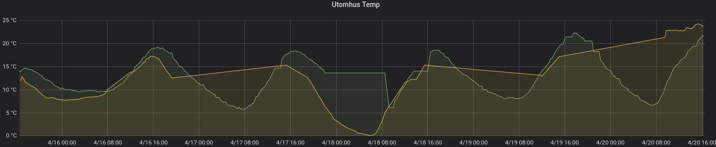
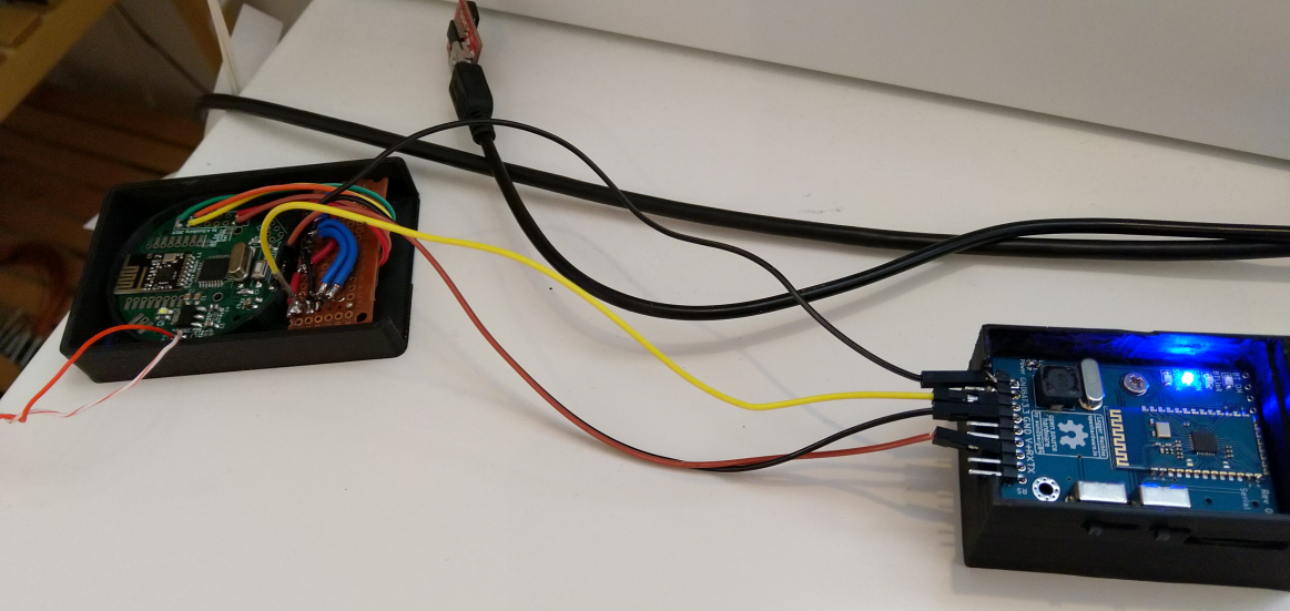
    Anyhow, Im very glad i build my logger node - works great once more. I use this so often and really recommend all with a bigger network to have some sort of mobile debugger. Most of the times I use the bluetooth module (2xAA powered) but at this point I have my node on my workbench powered by a USB adapter (orange wires). I then parasite power from the node to run the debugger and is now logging everything to a sd-card.

    503d3040-7208-4e95-a6cc-cb3128d24c17-image.png


  • Mod

    In case anyone hasn't seen the logger before, it is available at https://www.openhardware.io/view/532/The-Logger-Machine-Short-and-long-term-serial-logging


  • Hardware Contributor

    Another picture from today:
    cd572dd2-1092-478e-bb59-6200ef28ad7a-image.png

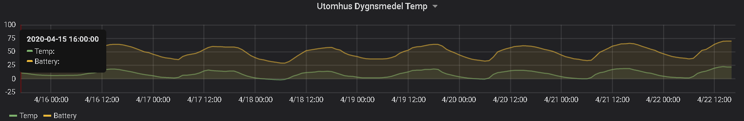
    Just started working with coincells - CR2032 to be exact. Anyone knows why the battery % varies with the given temperature? Are those coincells very temp. dependent or I have made a misstake somewhere... ???


  • Hardware Contributor

    @sundberg84 said in What did you build today (Pictures) ?:

    Anyone knows why the battery % varies with the given temperature

    They don't like it when it's too cold. Check page 4 :
    https://data.energizer.com/pdfs/lithiumcoin_appman.pdf


  • Mod

    @sundberg84 looks like you can ditch the temperarure sensor and just use the battery voltage to measure the temperature 💪


  • 20200422_132110_resized.jpg

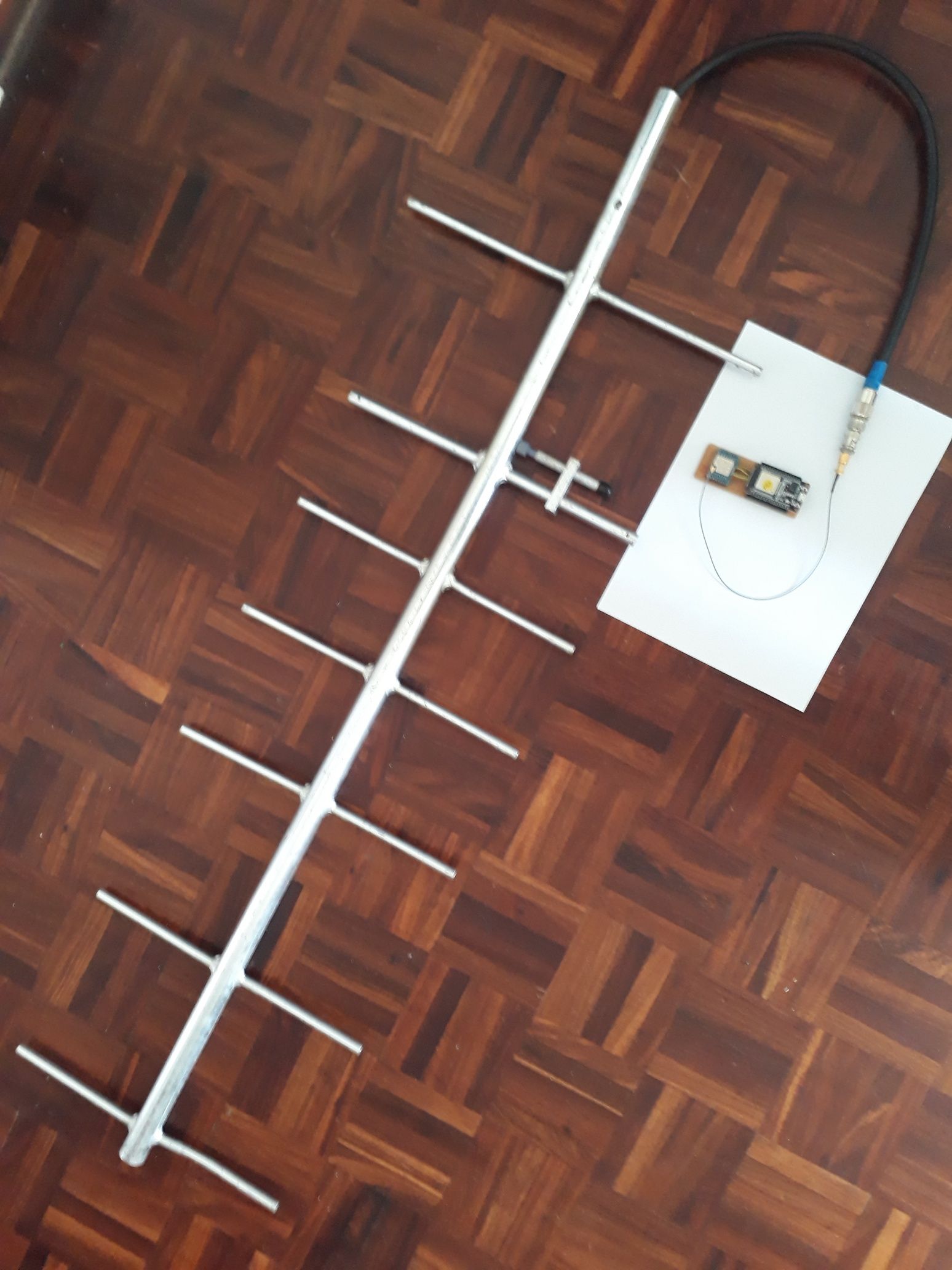
    433 MHz ESP 32 MQTT Gateway with proper antenna


  • Hardware Contributor

    @Nca78 - Well, its been around 14-17dgr C today, so almost room temp. Strange
    @Yveaux - hahaha, best answer! Saving uA!


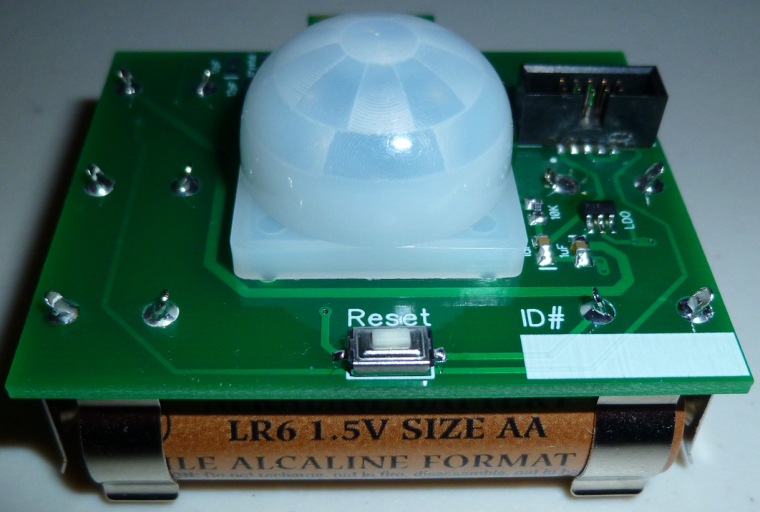
  • @NeverDie sorry if it's a bit off topic, but I see that 10 pin ARM box connector you use in several of your designs, and I was wondering if it offers anything extra in addition to the regular 6 pin programming pins. I'm asking specifically because I want to try some of your nrf52832 designs, but would like to avoid spending extra money on special connectors and cables. Thanks!


  • Hero Member

    @idanronen No, nothing extra. It just conveniently and transparently interfaces to the ribbon adapter cable used by the Nordic nrf52 dev kits for programming external nRF52 MCU's. If you want to roll-your-own, you can do away with most of the pins. I myself migrated to a smaller connector in later designs.


  • @NeverDie thanks for clarifying!
    So for example in the mini breakout board (https://www.openhardware.io/view/471/Ebyte-nRF52832-Small-Breakout-Board) I could just align the 6 pads and use a standard 6 pin pogo programmer right?


  • Hero Member

    @idanronen Yup. If you have more questions, you should probably ask them on a different thread than this one, as it's off topic here.


  • Offtopic in terms of mysensors platform, but somehow tangent to a home automation. I've made a batch of concrete switches/push buttons which are in this case simple buttons with led backlight and all the logic is located centrally in distribution box, based on KNX ABB module. But I am planning on making smarter and more complex version which could use Mysensors as its transport.
    _MG_6056.jpg
    _MG_6063.jpg
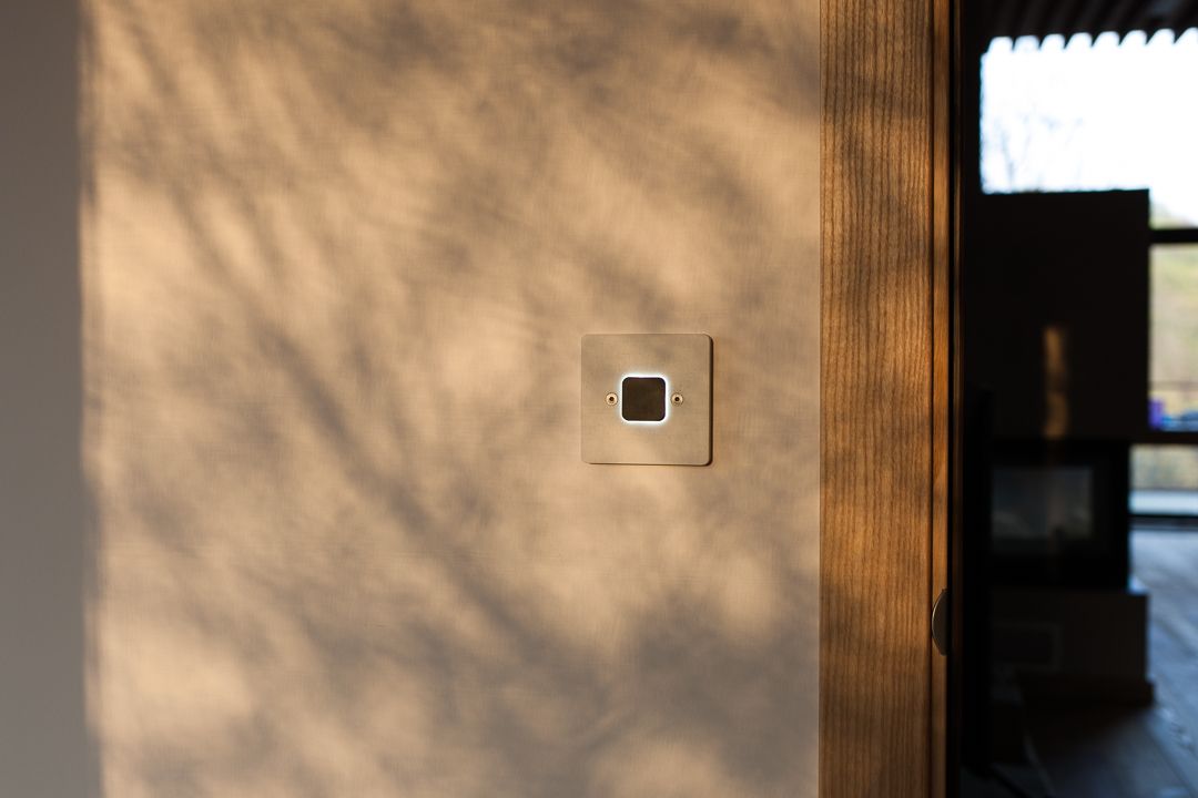
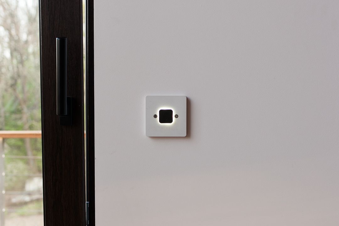
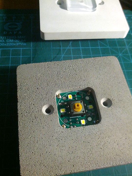
    and a photo of insides of one of the prototypes at first stages of development
    11.jpg


  • @monte Nice work! I love the looks of the concrete switches, do you have some links or useful information on how you did it.
    I have a project of a doorbell that could use such a switch.

    Thanks!


  • Hero Member

    @monte It's a real pleasure to see such professional looking design!

    I'm curious though: the button in your teardown looks clear:
    alt text
    so how does it turn black and give the solar eclipse effect? I mean, I can see the 4 LED's that comprise the "sun," but how does the button (the "moon" in this analogy) go from clear to black?


  • @NeverDie tanks for describing it as "professional":)
    The clear button on the last photo was one of prototypes as I've mentioned, frankly process of refining the button part to make it work as it should was the longest part of the development. Now it is made in two stages: at first the transparent acrylic part is cut on laser machine, then it placed into a mold with curing mix of resin and concrete, which makes it's black top layer that blocks the light from below. 3mm acrylic base and 2mm resin top layer.
    But I have to say that next batches will be made the other way, which is already in my mind:)

    @MatiasV thanks! Well, I coluld describe the whole process of making, but it requires a lot of work like making propper mold, the process of trial and error while trying to achieve consistant pour and at last the complex process of making a button that would work without sticking.
    Frankly I don't think it's worth time and effort if you plan tho do only one switch for yourself. But I can give you hints about concrete mixture and other stuff, if you're just interested in it's concrete part.


  • Hero Member

    @monte Now that you've mastered the medium you can cast your own tile to texture a wall:
    alt text

    I met a local architect who did such a thing for her own home. She only had to create a handful of different molds, and then random placement gave the illusion of more than that. Maybe they could be secret panels for hiding all your home automation control equipment behind. High WAF that would be. 😁


  • Admin

    Just made a fun (and useful) sensor / device, using a arduino pro-micro (atmega32u4), and VL53L01 TOF distance sensor.

    It's an auto lock device for my pc, I have mounted the VL53L01 to the bottom of my center monitor, and then have it measure the distance to my body, whenever it exceeds 1m (or is out of range), I increase a counter. When the counter reaches 20 (seconds) I send keypress GUI+L, to lock the screen (works equally well on ubuntu and windows).

    When I return to the desk again, it is detected by the arduino (distance is now under 1m again). And it then sends CTRL+ALT+DEL to start login procedure.

    The arduino sketch is available on https://gist.github.com/tbowmo/7e9934796d47566dc09e7b3bc5b2f208

    next project should probably be to find a better enclosure, and build one for when I return to the office in a month or two, when the corona lockdown is lifted more

    f28a180c-322f-4360-ae28-1a4efc93ecad-billede.png

    8cdc94f7-be29-4706-986e-9583c7c5cd25-billede.png


  • @sundberg84

    I finished my fully functional panel for domoticz, using Display Nextion ...

    I don't know where to post, sorry !!! lol

    20200514_202815.jpg 20200516_211738.jpg 20200516_211820.jpg 20200516_211810.jpg 20200516_211815.jpg


  • Hardware Contributor

    Interupted by our first "Summer" lightning, but in replacing my old Rfm69 gateway (old one works, but uses a ftdi adapter for Serial communication and i have another need for the adapter). In the same time im taking up signing. The node has a atsha chip but I never used it properly which im going to try to fix.

    IMG_20200523_162944.jpg


  • Hi guys,

    today I have finished the 3d printable case of the d-diot hub.

    20200524_101250.jpg 20200524_101318.jpg 20200524_101419.jpg 20200524_101329_HDR.jpg 20200524_101340.jpg

    The hub basically is a Raspberry Pi 3 with the d-diot board (see this topic) that offers the following functionalities:

    • IR Gateway (blaster and receiver) to control every device that has a dummy infrared remote.

    • 433 Mhz Gateway with the RFLink firmware running on the on-board ATMega2560 microcontroller

    • Dual MySensors Gateway: NRF24 (2.4 Ghz) and RFM69 (868 Mhz).

    • Latch circuit to power-on and safely power-off your Pi with a simple button press.

    • SSD1306 I2C Oled display controllable in Home Assistant

    • Radio activity LEDs for IR and Mysensors gateways

    • Nice and powerful web interface thanks to Home Assistant

    • Easy setup and configuration with the d-diot image

    If someone is interested, here the detailed build instructions.


  • @NeverDie My experience shows that the Chinese sensors that are sold on Aliexpress have a low quality printed circuit Board. When used outdoors, they may deteriorate within 1-2 seasons. Inside the house, in a flower pot, the service life is much longer. As for such sensors developed independently, the quality of printed circuit boards that are ordered through the services of jlcpcb, pcbway... very high.


  • @NeverDie I personally took a bottle of nail polish and coated every sensor I had. I had a hunch that moisture seeping might affect the capacitive sensors so I took precautions. They've lasted a year now with no sign of deteriorating.


  • Hero Member

    Thanks! Earlier in 2020 I started a shoot-out of different weatherproofing coatings, and I can already see that Spray Max 680061 is by far performing the best out of all the hard coatings that I tried: https://www.spraymax.com/en/products/product/clear-coats-and-spot-blender/2k-clear-coat/ So, for that reason, I suspect it would also perform very well at moisture proofing capacitive PCB soil probes.


  • Hero Member

    I built a picoamp current source and tested a picoammeter that I built from Gyro's design that was posted on the EEVblog forum. It turns out it can measure even single digit picoamps to an accuracy of less than a picoamp (i.e. less than one trillionth of an amp!)

    calibration_2mb.JPG

    https://www.eevblog.com/forum/beginners/static-control-requirements-for-picoamp-measurements-using-ucurrent-gold/msg3101836/#msg3101836


  • Today I finally found some time to put a few modules together.
    A cheap solar cell (€1.35 a piece) with recharcheable battery which feeds via a step-up converter (€0.70 /pc) a pro-mini (5VDC). The DS18B20 is read every 5 minutes.
    Now I’m Interested how long this sensor will do its job.

    IMG_4200.jpg


  • Hi, everybody. Yesterday I made a case for my new device with an e-ink display 2.7. the Case turned out to be quite thin. The dimensions of the device in the case are 86.5 mm X 59.5 mm X 11.5 mm. The new device is a continuation of the project - https://www.openhardware.io/view/629/EFEKTA-TempandHum-sensorver-nRF52-E-Ink-display

    photo_2020-07-16_14-59-38.jpg photo_2020-07-16_14-59-41.jpg


  • Plugin Developer

    Man, things are starting to look very professional around here.


  • Made a prototype board for writing a software for one of my projects. Goal was to have everything needed on a board no bigger then a 1.54" eink display, and to make it doable at home by my own.
    I was gladly surprised that everything worked (after a sleepless night of fighting through-layer connections, and soldering/desoldering FPC connectors) 🙂 The only I've messed up is order of connector pins, so the display is connected the wrong way...
    IMG_20200723_172110.jpg
    IMG_20200723_162420.jpg

    It also has pads for SHT30 sensor so it may be somehow useful after development is done.


  • @monte said in What did you build today (Pictures) ?:

    FPC

    Excellent handwork. I also dealt with such FPC conectors :), here are the correct FPC conectors - https://aliexpress.ru/item/32794813863.html


  • @berkseo Thanks!
    Link doesn't open. I have the right ones, I've just messed up PCB layout. Somehow pins on the board goes in the wrong direction, so the most left pin is #24 instead of #1 🙂


  • @monte fixed the link, html.... not htm


  • @monte By the way, this version of screens is discontinued, it is better to develop software for new versions


  • @berkseo thanks for mentioning that. But as I understand the change in software would be just including another header file, if I'm using GxEPD library. There is a mention on github that there is GDEH0154D67 model as a replacement for GDEP015OC. Or do you mean that they are discontinuing 1.54" displays completely?


  • @monte said in What did you build today (Pictures) ?:

    Or do you mean that they are discontinuing 1.54" displays completely?

    Yes, I mean that these displays are no longer produced. And it is better to focus on new ones.


  • @berkseo well, that's a shame. They are the perfect size for my purpose. I guess I need to stock few of them, while I can 🙂 Thanks for the tip!


  • @berkseo said in What did you build today (Pictures) ?:

    @monte said in What did you build today (Pictures) ?:

    Or do you mean that they are discontinuing 1.54" displays completely?

    Yes, I mean that these displays are no longer produced. And it is better to focus on new ones.

    Just to clear up a potential misunderstanding: The 1.54" EPDs aren't going to vanish anytime soon. Only the GDEP015OC1 has been discontinued and the GDEH0154D67 may follow, too at some point.

    But Dalian Good Display has just launched the GDEW0154M09 this month, which seems to be the successor of the GDEH0154D67 at first sight. There is also the GDEW0154M10, which supposedly has a better contrast due to a new manufacturing process. Waveshare seems to be still selling their version of the GDEH0154D67, but not any of the new ones.

    I don't think you need to hoard them like other poeple hoard their live-long stock of toilet paper these days. 😉


  • My super simple NRF51 touch buttons. I mostly use these to toggle overhead lights that I've converted to Tasmota.

    Screen Shot 2020-07-27 at 9.21.20 AM.png

    Screen Shot 2020-07-27 at 9.22.01 AM.png

    Screen Shot 2020-07-26 at 3.16.10 PM.png


  • Hero Member

    @ncollins Elegant. Does it talk to a gateway, which then talks to your Tasmota, or does it somehow talk directly to the Tasmota? So many things now have Bluetooth as part of them that the possibility of direct communication sometimes exists.


  • @NeverDie Buttons -> Mysensors Gateway -> OpenHab Rules -> Tasmota Switches / Outlets / Extension cords.

    I am tempted to explore the BLE route. It seems to support a majority of my sensor use cases, I like the idea of standardizing on the GATT protocol, and there are already a ton of tools and connectors in place.


  • @ncollins And this is my simple capacitive button, just a button:). Beginning of this story was like this:... once I bought a Chinese capacitive button and was very upset with the quality...
    IMG_20200728_170232.jpg


  • @tbowmo said in What did you build today (Pictures) ?:

    atmega32u4

    Next step: build an entire keyboard and flash QMK to it!
    Nice project, I thought about something similar but to operate a fan, which is way harder than communicating with a computer, I should have started with that.
    Very little nice sensor that one...


  • @monte Where do you buy that e-ink displays? they look awesome


  • @berkseo nice! Just today, I've ordered something similar but with an led mounted sideway, to make more diffused glow of the opaque resin that will cover these:
    6757ae58-33e1-4f37-a7a0-c3031b854aa0-image.png

    @Danielo-Rodríguez I've bought mine on aliexpress, but you can find them at several different places. They are produced by a company named Good Display (Dalian Good Display Co., Ltd to be precise). They have different sizes and colors with different price and performace too. Also they are sold by Waveshare, but the displays are the same, I believe.


  • The other day I received PCB of a long-awaited project. Yesterday and today, I soldered the device, designed and printed the case of the device. It works, wow!!!
    photo_2020-07-28_03-18-09.jpg
    photo_2020-07-29_02-25-59 (3).jpg
    photo_2020-07-29_02-25-59 (3).jpg
    photo_2020-07-29_02-25-59.jpg


  • Hero Member

    I'm surprised no one here has built anything Covid19 related--even something as basic as a handwashing timer or something like that. I, for one, am tired of singing songs to time myself, and getting kids to handwash for the full recommended duration is, well, something I'd rather let automation enforce instead of me! 😉


  • @NeverDie From these things, which are in the photo above, can make an informant COVID-19. Show the trend, the number of infected people to date in your location, and so on.


  • Mod

    A MySensor'ed temperature controller for my utility cabinet, which runs too hot due to all the electronics in there (cable modem, router, switch, etc.)
    In its current version it is able to control a 12V 120mm PWM fan, and reads the temperature from 3 DS18B20 temp sensors (inlet, 'ambient' and router).
    Later I might add a temperature controller to keep the ambient temperature stable at a a few degrees above inlet, by controlling the fan's dutycycle.

    As all sensors in my utility cabinet are powered from 5V USB, I used a step-up converter to generate the 12V required by the fan.

    v1.jpg

    After soldering everything together I wasn't happy with the orientation of the JST headers for the temp sensors, so a small PCB was added to mount them under 90 degrees:

    v2.jpg

    All data and control is routed to Node-red, stored in InfluxDB and graphed in Grafana:

    c7ff7fd0-44f4-4a33-9ec8-e7e03ce7aaf5-image.png

    You can see the temperature of the router ('USG') go down with increasing fan rotational speed (lower chart, 'rpm.mean').
    Temperature decrease is not as big as I hoped for, so I might need to install a fan with a bigger airflow.


  • My new gateway with leds for state and the only node I have: A wireless arcade button controller ea084163-e43a-4aad-ae0c-993085b04502-image.png


  • Mod

    @Danielo-Rodríguez you might already be aware of this, but all that metal close to the nrf24 antenna will probably block some signal.


  • Well, it not really a build I plugged in wires, and copied code. Found a random usb charger and put it all in my workspace to be.

    And I absolutely love this thing. Maximum of 3 hours work. I was having fun, so it could be more.

    I considered that there could and should be a display on this thing, but not for now. I made this, because I have never experimented with temperature sensors and I just received a few. Now I can just see what happens with the temperature in there.
    sensor is a AHT10 temperature and humidity.
    http://www.aosong.com/m/en/products-40.html
    I used this library: https://github.com/enjoyneering/AHT10
    I repurposed Hek's DHT code, and swapped the readings with the AHT's

    IMG_20200815_095309.jpg

    shed before
    IMG_20200531_192231_2.jpg

    workspace after but still filling it.
    IMG-20200812-WA0001.jpeg


  • Today I've finally swapped my outdoor relay node with something descent.
    IMG_6784.jpg
    This was my very first mysensors node that I've built when I was only starting to mess with arduino, probably around four years ago.

    IMG_6785.jpg
    IMG_6786.jpg
    This board uses cheap 5v power supply and an amplified version of NRF24 module from Ebyte. It supposed to be poured with silicone ore resin, but I am yet to find suitable box, the size of this board appeared to be bigger then most of such cases designed for compound pouring. But I'm planning on making next version, with non-isolated power supply, which will help to achieve smaller size.


  • My new project of a temperature and humidity sensor with an electronic ink display 1.02 Inch ( GDEW0102T4 ), very low power consumption, very small device.

    DIY Temperature and humidity sensor with an electronic ink display 1.02 Inch ( GDEW0102T4 ) – 06:19
    — Andrew EfektaSB

    IMG_20200909_111923.jpg


  • USB + ESP8266 adapter for W2812B LED strip.

    Well, this is actually a Tasmota + Openhab build, but could easily be MySensors.

    Also worth noting, this 5m 150 led strip draws too much current to reliably use with a USB wall adapter.

    62154743620__8CA02E53-F789-4B83-8D1D-C2E1D4F18423.jpeg

    62154729146__FDB896AA-6E42-4B25-93B1-6214813216EA.jpeg

    Messages Image(2477667489).png

    Messages Image(1253441685).png


  • Mod

    Very nice renderings.

    W2812B uses about 50mA at full brightness, so you'd need a power supply that can deliver 7,500mA if you run the entire strip at maximum.


Log in to reply
 

Suggested Topics

  • 4
  • 9
  • 933
  • 274
  • 2
  • 5

0
Online

11.2k
Users

11.1k
Topics

112.5k
Posts