What did you build today (Pictures) ?

-
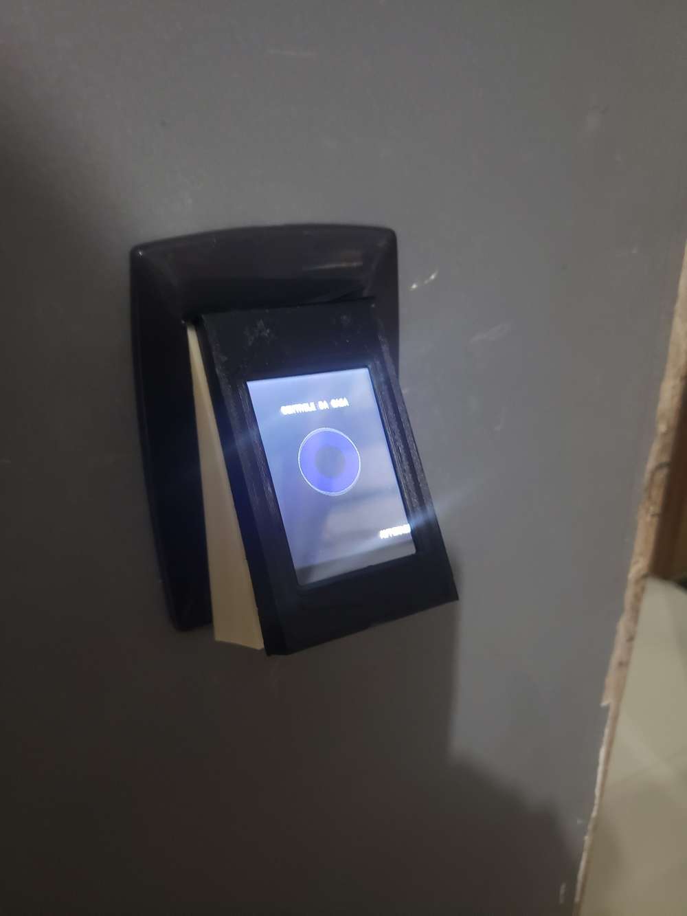
Offtopic in terms of mysensors platform, but somehow tangent to a home automation. I've made a batch of concrete switches/push buttons which are in this case simple buttons with led backlight and all the logic is located centrally in distribution box, based on KNX ABB module. But I am planning on making smarter and more complex version which could use Mysensors as its transport.
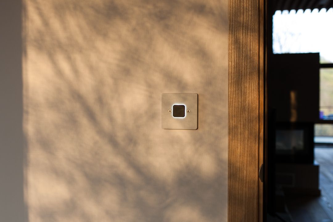
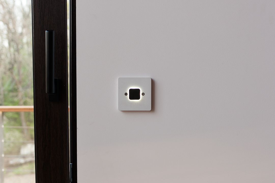
and a photo of insides of one of the prototypes at first stages of development
-
Offtopic in terms of mysensors platform, but somehow tangent to a home automation. I've made a batch of concrete switches/push buttons which are in this case simple buttons with led backlight and all the logic is located centrally in distribution box, based on KNX ABB module. But I am planning on making smarter and more complex version which could use Mysensors as its transport.
and a photo of insides of one of the prototypes at first stages of development
@monte It's a real pleasure to see such professional looking design!
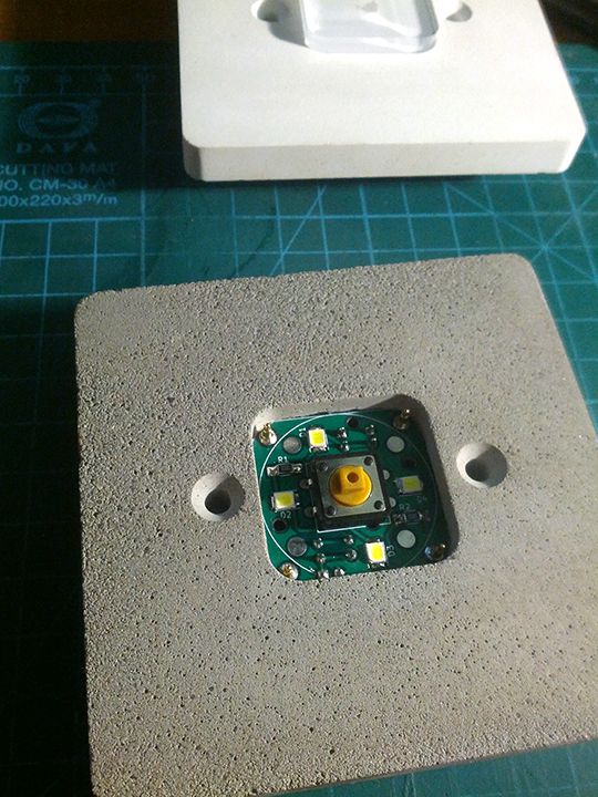
I'm curious though: the button in your teardown looks clear:

so how does it turn black and give the solar eclipse effect? I mean, I can see the 4 LED's that comprise the "sun," but how does the button (the "moon" in this analogy) go from clear to black? -
@monte It's a real pleasure to see such professional looking design!
I'm curious though: the button in your teardown looks clear:
so how does it turn black and give the solar eclipse effect? I mean, I can see the 4 LED's that comprise the "sun," but how does the button (the "moon" in this analogy) go from clear to black?@NeverDie tanks for describing it as "professional":)
The clear button on the last photo was one of prototypes as I've mentioned, frankly process of refining the button part to make it work as it should was the longest part of the development. Now it is made in two stages: at first the transparent acrylic part is cut on laser machine, then it placed into a mold with curing mix of resin and concrete, which makes it's black top layer that blocks the light from below. 3mm acrylic base and 2mm resin top layer.
But I have to say that next batches will be made the other way, which is already in my mind:)@MatiasV thanks! Well, I coluld describe the whole process of making, but it requires a lot of work like making propper mold, the process of trial and error while trying to achieve consistant pour and at last the complex process of making a button that would work without sticking.
Frankly I don't think it's worth time and effort if you plan tho do only one switch for yourself. But I can give you hints about concrete mixture and other stuff, if you're just interested in it's concrete part. -
@NeverDie tanks for describing it as "professional":)
The clear button on the last photo was one of prototypes as I've mentioned, frankly process of refining the button part to make it work as it should was the longest part of the development. Now it is made in two stages: at first the transparent acrylic part is cut on laser machine, then it placed into a mold with curing mix of resin and concrete, which makes it's black top layer that blocks the light from below. 3mm acrylic base and 2mm resin top layer.
But I have to say that next batches will be made the other way, which is already in my mind:)@MatiasV thanks! Well, I coluld describe the whole process of making, but it requires a lot of work like making propper mold, the process of trial and error while trying to achieve consistant pour and at last the complex process of making a button that would work without sticking.
Frankly I don't think it's worth time and effort if you plan tho do only one switch for yourself. But I can give you hints about concrete mixture and other stuff, if you're just interested in it's concrete part.@monte Now that you've mastered the medium you can cast your own tile to texture a wall:
I met a local architect who did such a thing for her own home. She only had to create a handful of different molds, and then random placement gave the illusion of more than that. Maybe they could be secret panels for hiding all your home automation control equipment behind. High WAF that would be. :grin:
-
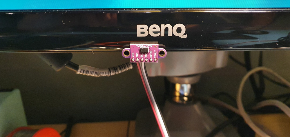
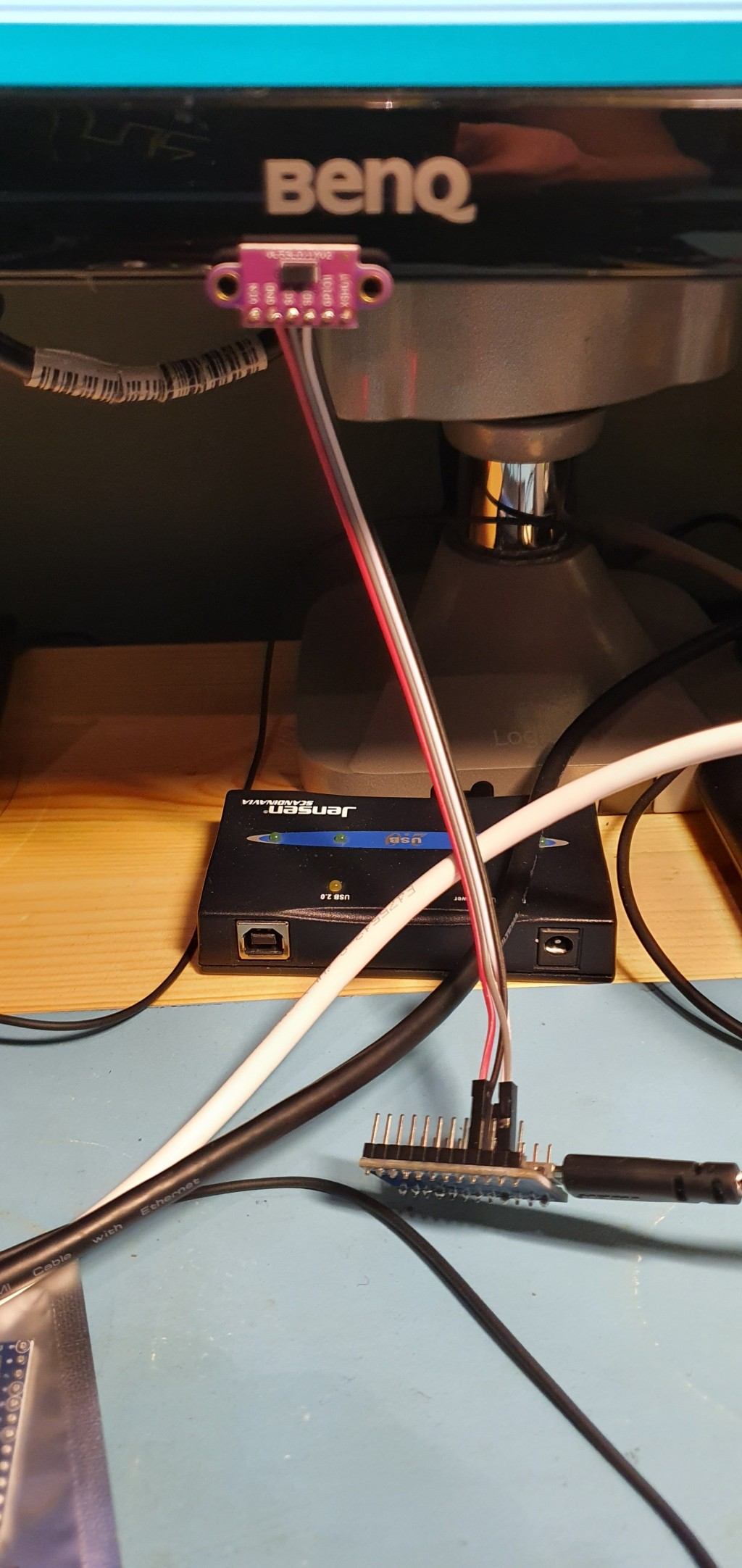
Just made a fun (and useful) sensor / device, using a arduino pro-micro (atmega32u4), and VL53L01 TOF distance sensor.
It's an auto lock device for my pc, I have mounted the VL53L01 to the bottom of my center monitor, and then have it measure the distance to my body, whenever it exceeds 1m (or is out of range), I increase a counter. When the counter reaches 20 (seconds) I send keypress GUI+L, to lock the screen (works equally well on ubuntu and windows).
When I return to the desk again, it is detected by the arduino (distance is now under 1m again). And it then sends CTRL+ALT+DEL to start login procedure.
The arduino sketch is available on https://gist.github.com/tbowmo/7e9934796d47566dc09e7b3bc5b2f208
next project should probably be to find a better enclosure, and build one for when I return to the office in a month or two, when the corona lockdown is lifted more
-
I think we need a thread (and it would be fun) where old and new users can post a picture with a small text with "look what I did today". Its a steal from another forum i watch but its a really fun thread to follow like-minded people in their daily work.
The rules are simple - keep it simple with one picture (or a few) with a small text including a small explanation. If you want to comment on a particular post please create a new thread ("Reply as topic") or keep it really short. The idea is to get a flow with pictures. It does absolutely not needs to be a finished project - it can be a sketch of an idea or a process of something. Anything you can take a picture off from the MySensors / Home automation world.
I hope this is not violating any forum rules and if it does, please remove - but I think this can be a fun addition to the forum.
Let me start!
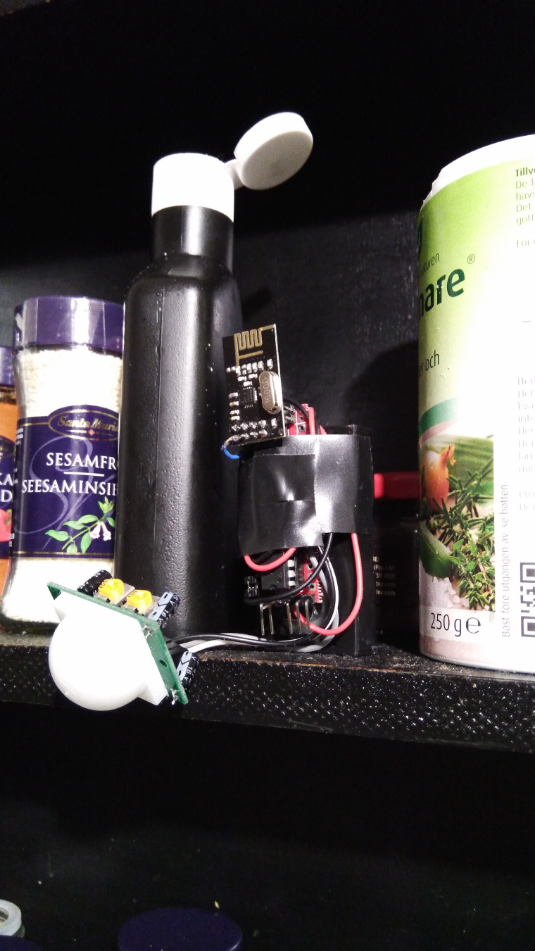
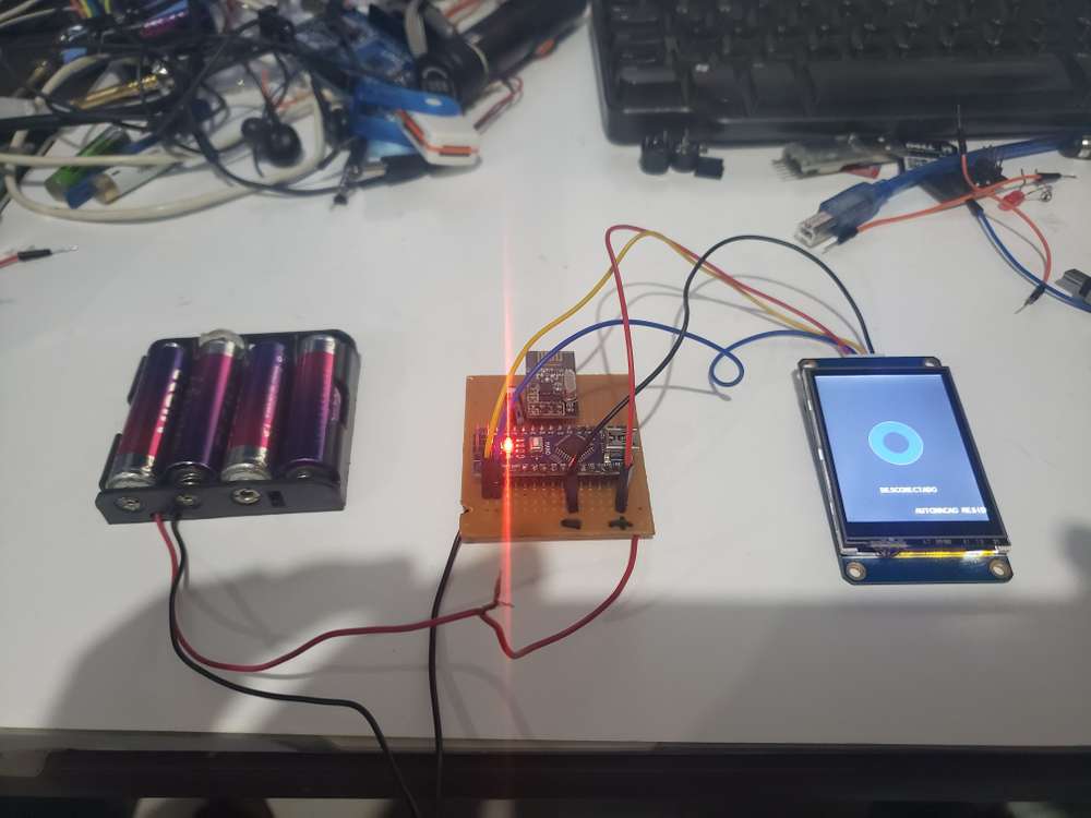
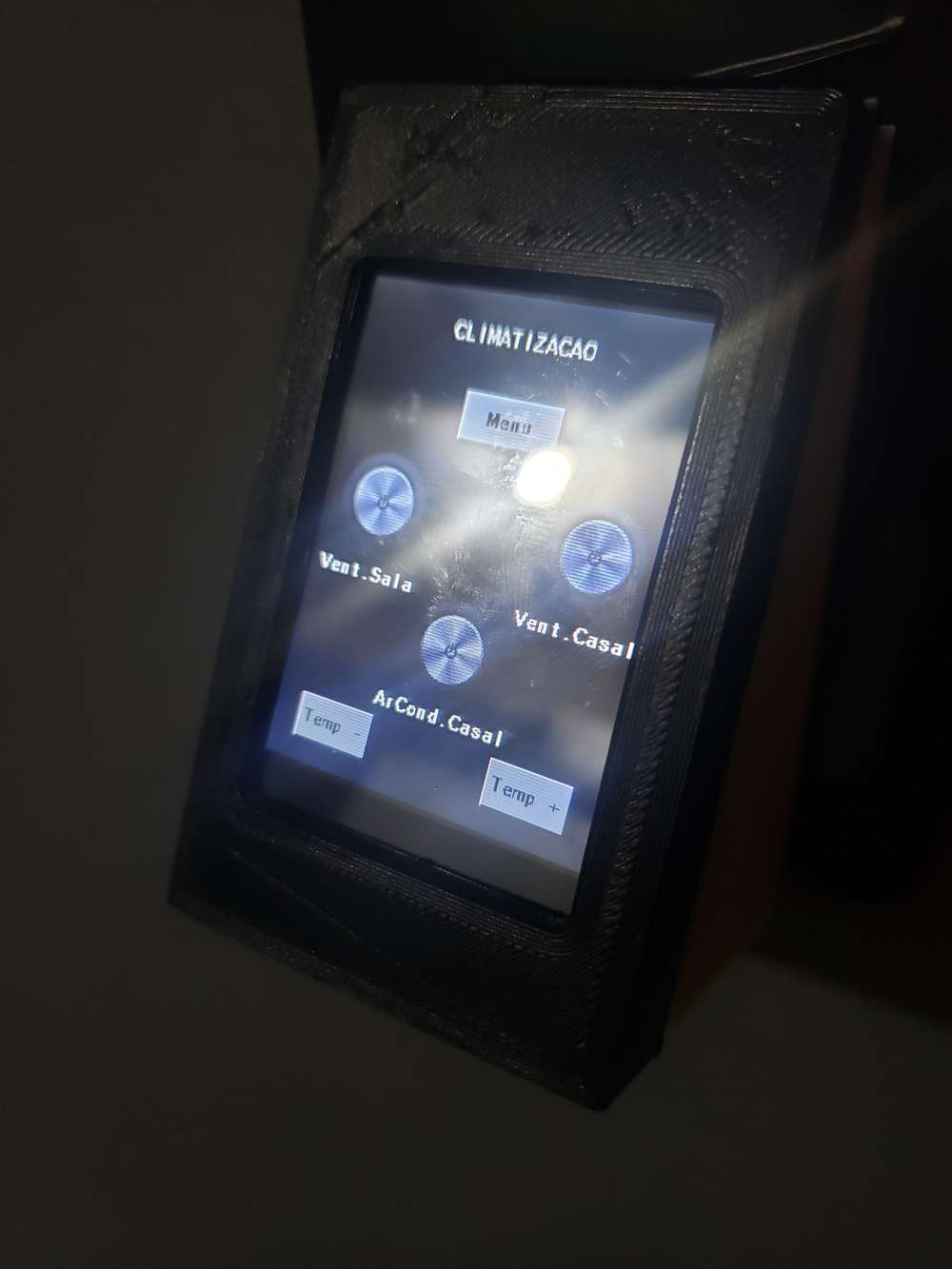
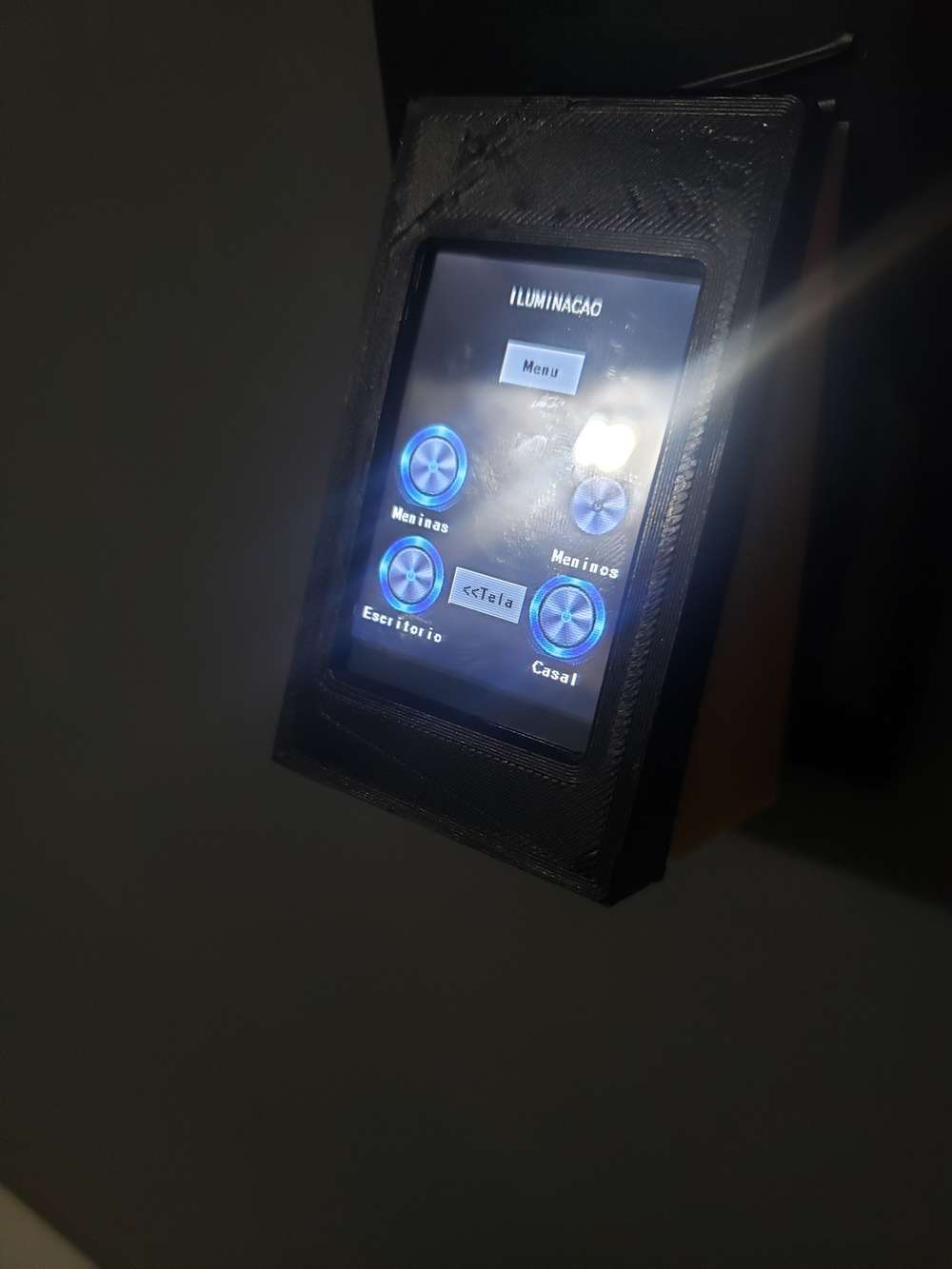
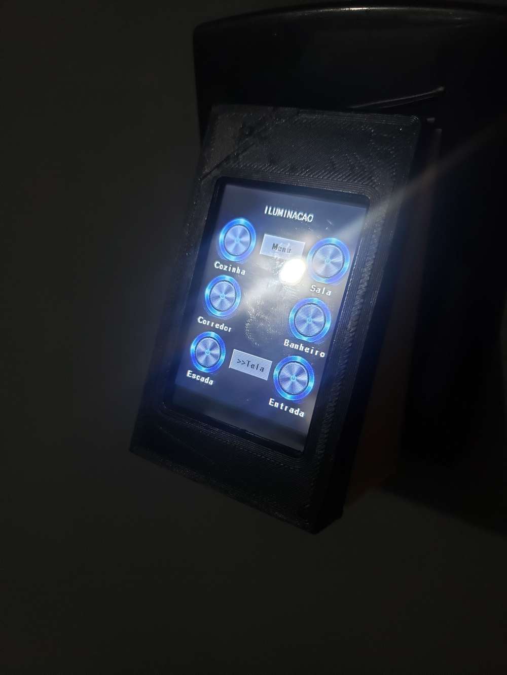
Today i created a second motion detector based on Slim Node from @m26872. Its a 1mhz bootloader and modified hc-sr501(3.3v "hack"). Its currently "deployed" in my kitchen (replaced the old one) in the spice-rack above the stove... low WAF but high camouflage! Might work :)I finished my fully functional panel for domoticz, using Display Nextion ...
I don't know where to post, sorry !!! lol
-
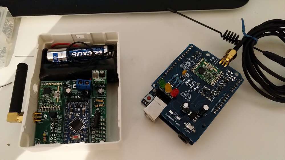
Interupted by our first "Summer" lightning, but in replacing my old Rfm69 gateway (old one works, but uses a ftdi adapter for Serial communication and i have another need for the adapter). In the same time im taking up signing. The node has a atsha chip but I never used it properly which im going to try to fix.
-
Hi guys,
today I have finished the 3d printable case of the d-diot hub.
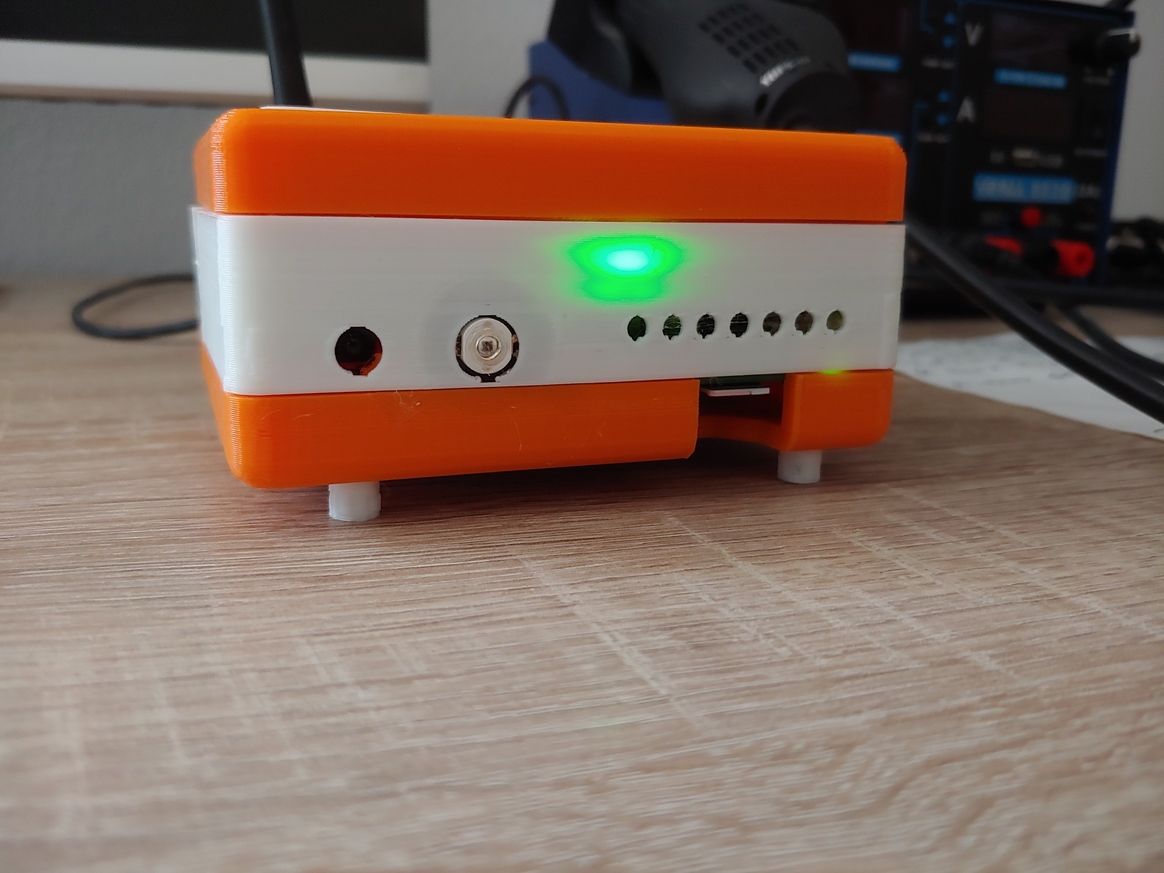
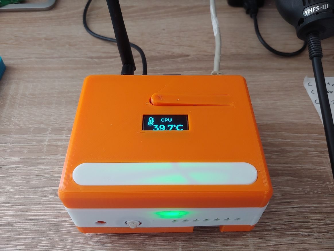
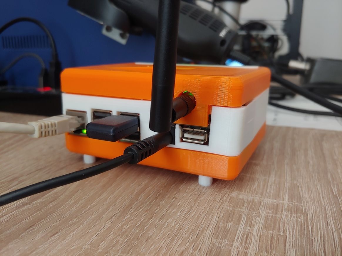
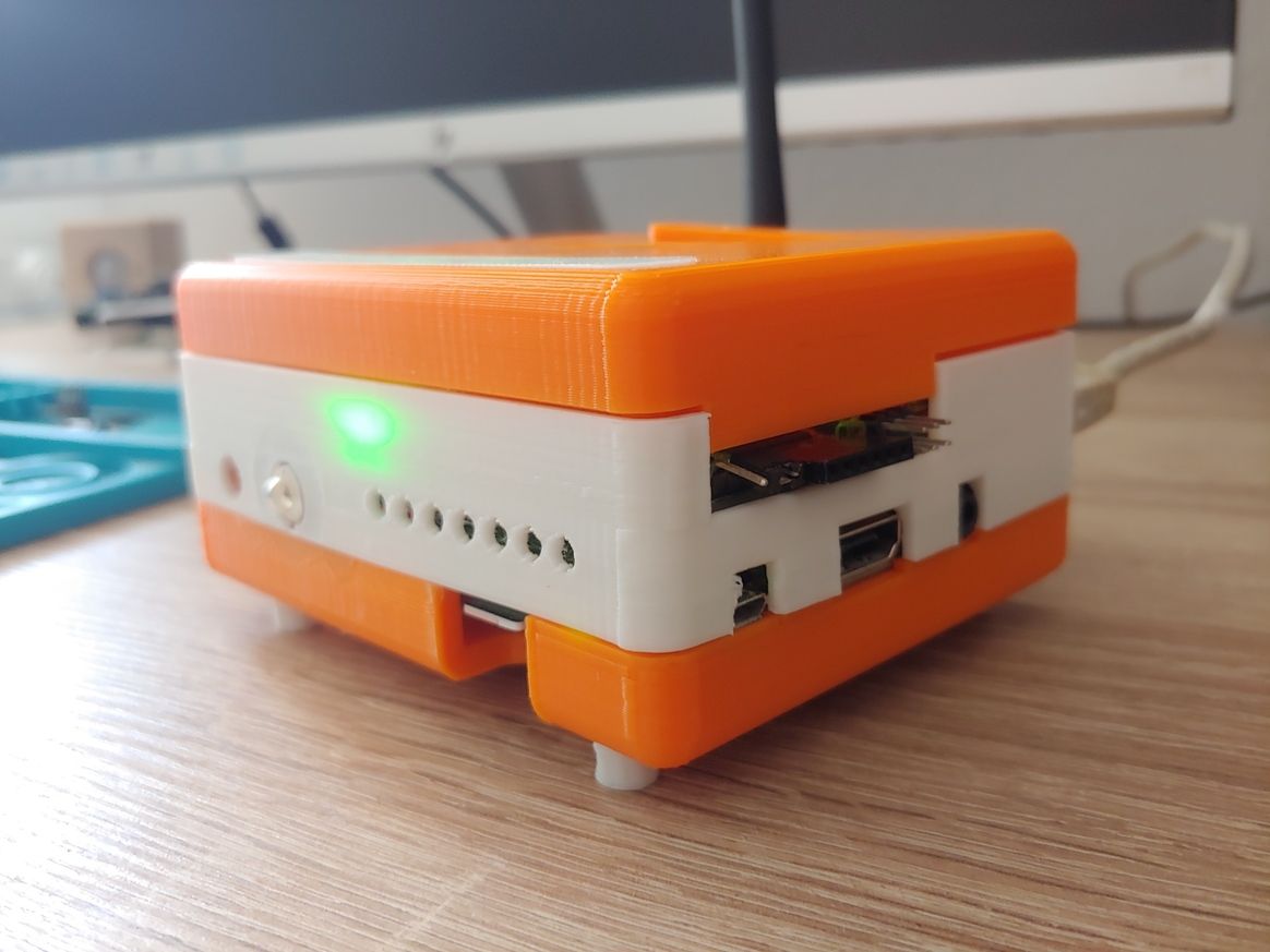
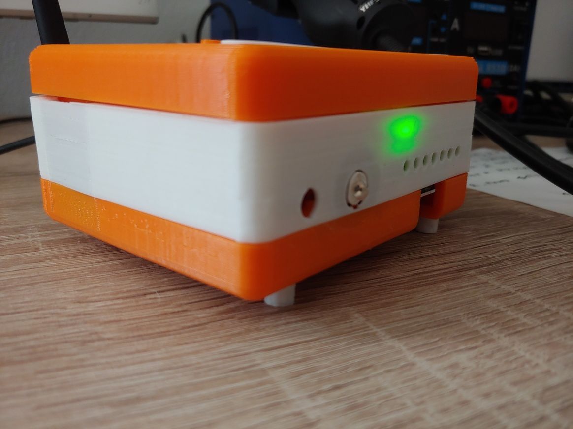
The hub basically is a Raspberry Pi 3 with the d-diot board (see this topic) that offers the following functionalities:
-
IR Gateway (blaster and receiver) to control every device that has a dummy infrared remote.
-
433 Mhz Gateway with the RFLink firmware running on the on-board ATMega2560 microcontroller
-
Dual MySensors Gateway: NRF24 (2.4 Ghz) and RFM69 (868 Mhz).
-
Latch circuit to power-on and safely power-off your Pi with a simple button press.
-
SSD1306 I2C Oled display controllable in Home Assistant
-
Radio activity LEDs for IR and Mysensors gateways
-
Nice and powerful web interface thanks to Home Assistant
-
Easy setup and configuration with the d-diot image
If someone is interested, here the detailed build instructions.
-
-
Anyone know or have experience with how well the underlying capacitive soil moisture sensors hold up over the long term? Clearly they're better than the cheap conductive electrode kind, which for most people don't last very long at all, but I recollect reading that water ultimately invades the PCB enough on even the capacitive designs that it goes kaput. Maybe they've been improved since then or maybe there are now known tricks for how to fortify them against that happening?
@NeverDie My experience shows that the Chinese sensors that are sold on Aliexpress have a low quality printed circuit Board. When used outdoors, they may deteriorate within 1-2 seasons. Inside the house, in a flower pot, the service life is much longer. As for such sensors developed independently, the quality of printed circuit boards that are ordered through the services of jlcpcb, pcbway... very high.
-
Anyone know or have experience with how well the underlying capacitive soil moisture sensors hold up over the long term? Clearly they're better than the cheap conductive electrode kind, which for most people don't last very long at all, but I recollect reading that water ultimately invades the PCB enough on even the capacitive designs that it goes kaput. Maybe they've been improved since then or maybe there are now known tricks for how to fortify them against that happening?
-
Thanks! Earlier in 2020 I started a shoot-out of different weatherproofing coatings, and I can already see that Spray Max 680061 is by far performing the best out of all the hard coatings that I tried: https://www.spraymax.com/en/products/product/clear-coats-and-spot-blender/2k-clear-coat/ So, for that reason, I suspect it would also perform very well at moisture proofing capacitive PCB soil probes.
-
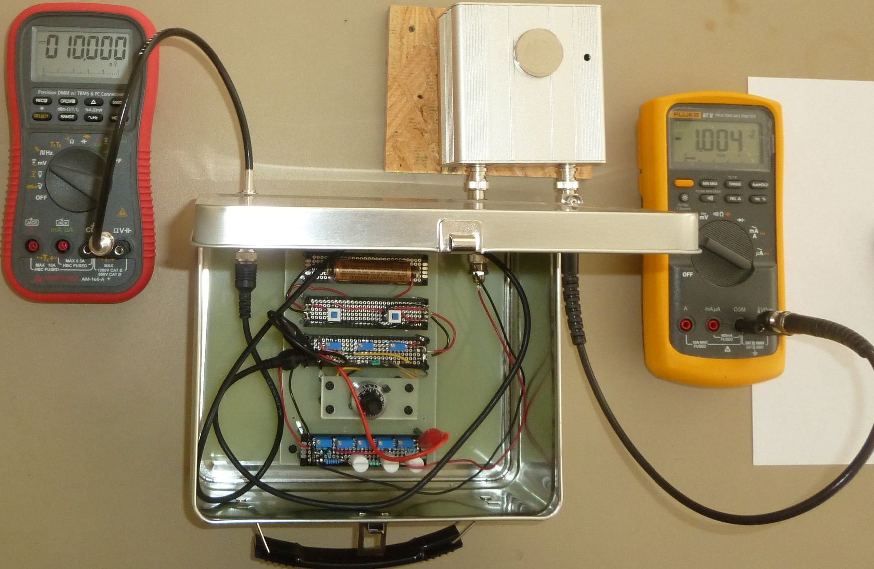
I built a picoamp current source and tested a picoammeter that I built from Gyro's design that was posted on the EEVblog forum. It turns out it can measure even single digit picoamps to an accuracy of less than a picoamp (i.e. less than one trillionth of an amp!)
-
I built a picoamp current source and tested a picoammeter that I built from Gyro's design that was posted on the EEVblog forum. It turns out it can measure even single digit picoamps to an accuracy of less than a picoamp (i.e. less than one trillionth of an amp!)
Today I finally found some time to put a few modules together.
A cheap solar cell (€1.35 a piece) with recharcheable battery which feeds via a step-up converter (€0.70 /pc) a pro-mini (5VDC). The DS18B20 is read every 5 minutes.
Now I’m Interested how long this sensor will do its job.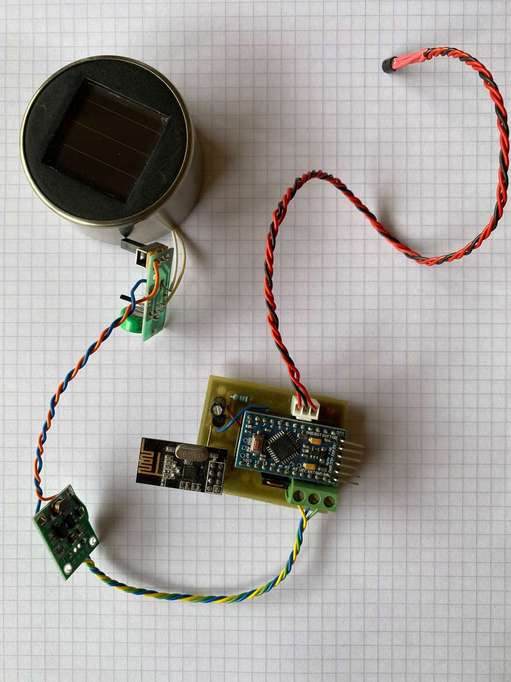
-
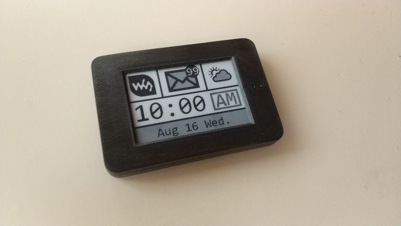
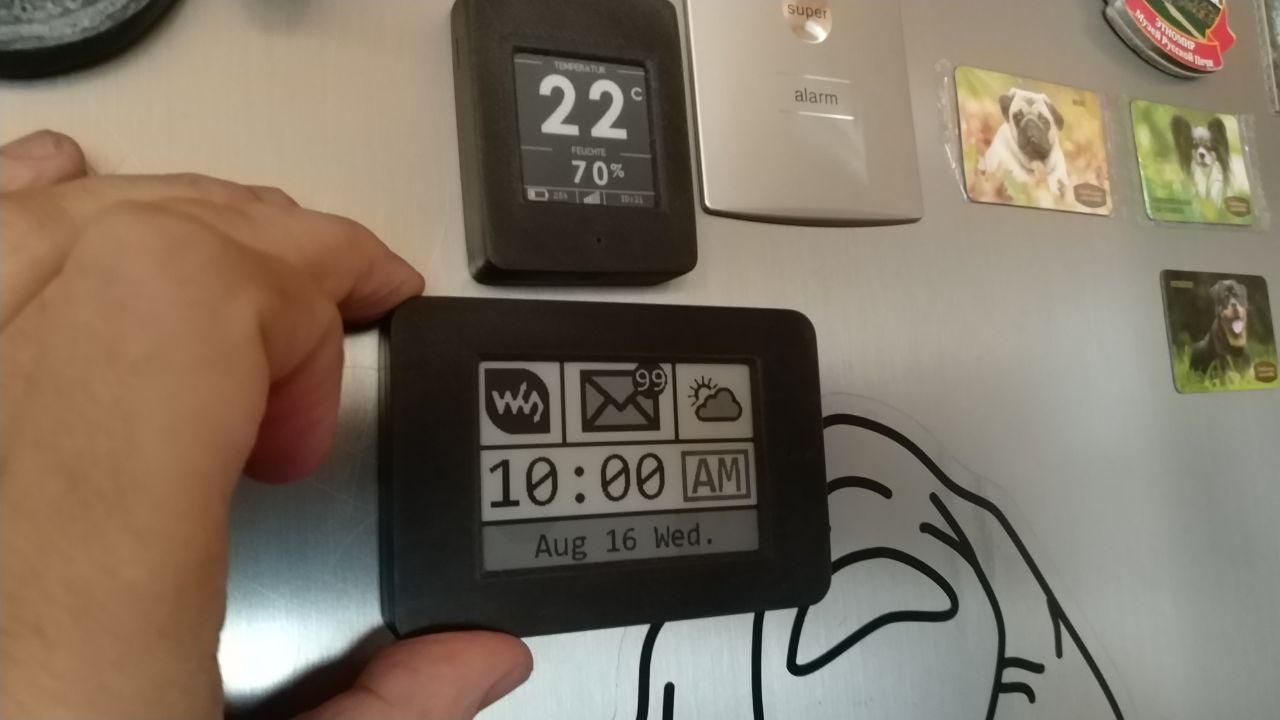
Hi, everybody. Yesterday I made a case for my new device with an e-ink display 2.7. the Case turned out to be quite thin. The dimensions of the device in the case are 86.5 mm X 59.5 mm X 11.5 mm. The new device is a continuation of the project - https://www.openhardware.io/view/629/EFEKTA-TempandHum-sensorver-nRF52-E-Ink-display
-
Man, things are starting to look very professional around here.
-
Made a prototype board for writing a software for one of my projects. Goal was to have everything needed on a board no bigger then a 1.54" eink display, and to make it doable at home by my own.
I was gladly surprised that everything worked (after a sleepless night of fighting through-layer connections, and soldering/desoldering FPC connectors) :) The only I've messed up is order of connector pins, so the display is connected the wrong way...
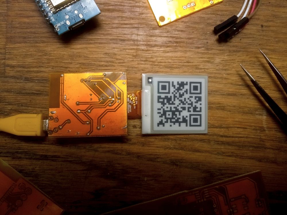
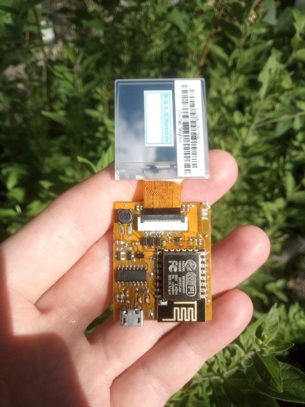
It also has pads for SHT30 sensor so it may be somehow useful after development is done.
-
Made a prototype board for writing a software for one of my projects. Goal was to have everything needed on a board no bigger then a 1.54" eink display, and to make it doable at home by my own.
I was gladly surprised that everything worked (after a sleepless night of fighting through-layer connections, and soldering/desoldering FPC connectors) :) The only I've messed up is order of connector pins, so the display is connected the wrong way...
It also has pads for SHT30 sensor so it may be somehow useful after development is done.
@monte said in What did you build today (Pictures) ?:
FPC
Excellent handwork. I also dealt with such FPC conectors :), here are the correct FPC conectors - https://aliexpress.ru/item/32794813863.html
-
@monte said in What did you build today (Pictures) ?:
FPC
Excellent handwork. I also dealt with such FPC conectors :), here are the correct FPC conectors - https://aliexpress.ru/item/32794813863.html
-
@berkseo Thanks!
Link doesn't open. I have the right ones, I've just messed up PCB layout. Somehow pins on the board goes in the wrong direction, so the most left pin is #24 instead of #1 :) -
@berkseo Thanks!
Link doesn't open. I have the right ones, I've just messed up PCB layout. Somehow pins on the board goes in the wrong direction, so the most left pin is #24 instead of #1 :)