DIY Outdoor LED
-
There is no information on which mosfet in the ebay listing. I would one that has a name/number so the data sheet can be looked up. The MySensors store recommends IRLZ44N.
Downside with mosfet: can become hot, might need a heat sink
Upside with mosfet: can be used to dim the lightsBy the way, how are you planning to get the power to the units? 12V from your house into the garden? In that case you might get problems if your garden is large, transferring power over long distances with low voltage is hard.
-
Will the FET get hot even with 2.4A when its rated for much more?
I am thinking of building one node and trying it out to see if there is any fallout. This will be for my landscape lights so its not like it will be running 24/7.
The plan IS to run a 14/2 wire running 12V. I could do 12/2 if the voltage drop is too bad. My runs should not be obscenely long...I guess I will have to just try and see what the drop is.
Thanks again for all your feedback.
-AM
@activemind said:
Will the FET get hot even with 2.4A when its rated for much more?
Probably not. As long as you check the rating you should be fine.
The plan IS to run a 14/2 wire running 12V. I could do 12/2 if the voltage drop is too bad. My runs should not be obscenely long...I guess I will have to just try and see what the drop is.
14 AWG has a resistance of 0.00829 ohm per meter (source). Assuming you have 15m from the outlet to the light, the resistance in the cable will be 0.2487 ohm (0.00829 * 15 * 2). At 2.4A that will result in a voltage drop of 2.4 * 0.2487=0,60V. That shouldn't be a problem.
If the distance from the outlet to the lights is longer, and you want to connect multiple lights without running multiple cables, the calculation doesn't look very good. Let's say the cable needs to be 30m and you want 5 lights, then we have a cable resistance of 0.00829 * 30 * 2=0.5 ohm and a voltage drop of 2.4 * 5 * 0.5=6V :exclamation:
12 AWG will give you 0.00521 * 30 * 2=0.3126 ohm and 2.4 * 5 * 0.3126=3,75V voltage drop which also might be too much. -
I would put my distance around 20m so that should be okay but I DO plan on putting multiple of these on a single run hence larger current!
I really dont want to do multiple runs.
Two options:
- I need to see how bright the light is with < 12V ?
- Use some regulator to bump up the voltage at the location. I will be building a seperate box anyways to house the FET and MySensors circuitry, so maybe put a regulator there?
What do you think?
-AM
-
Option 2 would require larger current (2.4A at 12V will require at least 4.8A at 6V) so the problem just gets worse. Better to increase the voltage, maybe run 24V and regulate down to 12V at each light?
@mfalkvidd
But i already have server grade 12v power supplies and i dont want to buy new ones.Is the LED really going to draw 2.4A? I will hook up one today and measure.
What's the max safe amount of current i can carry on 14/2 LV wire?
If push comes to shove, i might do multiple runs 😢
-AM
-
@mfalkvidd
But i already have server grade 12v power supplies and i dont want to buy new ones.Is the LED really going to draw 2.4A? I will hook up one today and measure.
What's the max safe amount of current i can carry on 14/2 LV wire?
If push comes to shove, i might do multiple runs 😢
-AM
Each led would draw around 410ma
5/12=.416 -
Each led would draw around 410ma
5/12=.416@Boots33 correct! I edited my previous calculation. Sorry for misleading you @activemind My voltage drop calculations are off by 5x so you will be able to use 5 lights instead of 1 at 2.4A. That means you'll only get in trouble if you plan to use 20+ lights.
-
@Boots33 correct! I edited my previous calculation. Sorry for misleading you @activemind My voltage drop calculations are off by 5x so you will be able to use 5 lights instead of 1 at 2.4A. That means you'll only get in trouble if you plan to use 20+ lights.
-
Slightly off topic question, but I am looking for a benchtop power supply (yeah! been managing without one for so long) and wanted y'all opinion on this:
Or
Or something else that doesnt cost a fortune.(<$100).
-AM
-
Or this one looks interesting too...good reviews on Amazon
-
Ended up blowing the regulator on a 5V pro mini when powered at 12V. Maybe its the "clone" part from china that is causing this but it gave out smoke and finally died when powered at 9V.
Going to assemble another 5V pro mini and power at 5V to test the board and circuit.
Thinking about putting a hefty 150R 1W ressistor before feeding 12V to RAW in final circuit.
Thoughts?
-AM
-
Ended up blowing the regulator on a 5V pro mini when powered at 12V. Maybe its the "clone" part from china that is causing this but it gave out smoke and finally died when powered at 9V.
Going to assemble another 5V pro mini and power at 5V to test the board and circuit.
Thinking about putting a hefty 150R 1W ressistor before feeding 12V to RAW in final circuit.
Thoughts?
-AM
You could also use an external regulator module to supply the 5v. at the moment you are running right on the pro mini maximum voltage which in my mind is never a good thing for long term reliability. I have used these modules with great success, they work with a wide level of input voltage and can be adjusted, so can be set to 5v or 3v output . They are quite cheap as well so if you have the room they may be worth a look.
-
Yeah, those would work good and I can feed 5V rather than 12V ar RAW pin.
How are these adjusted to output 5V?
edit: nevermind, I see the pot screw to adjust the output voltage.
-AM
-
assembled another pro mini board and powered it using 5V wall wart this time, no 3v3 on the board. I think I blew 662K part too.
Let me try replacing it.
-AM
-
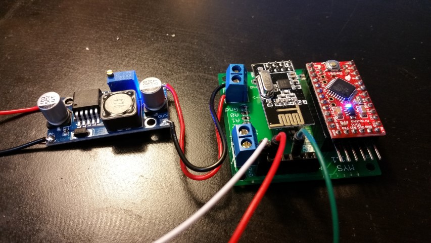
replaced the 662K part and now it seems to be working fine. I dug up my stash and found one step down converter like above. Let me power the node using it and see how it goes.
-AM
-
Powering a motion sensor sketch using the buck converter above. I wish I had my 12V relays in...
Here is a pic:
-
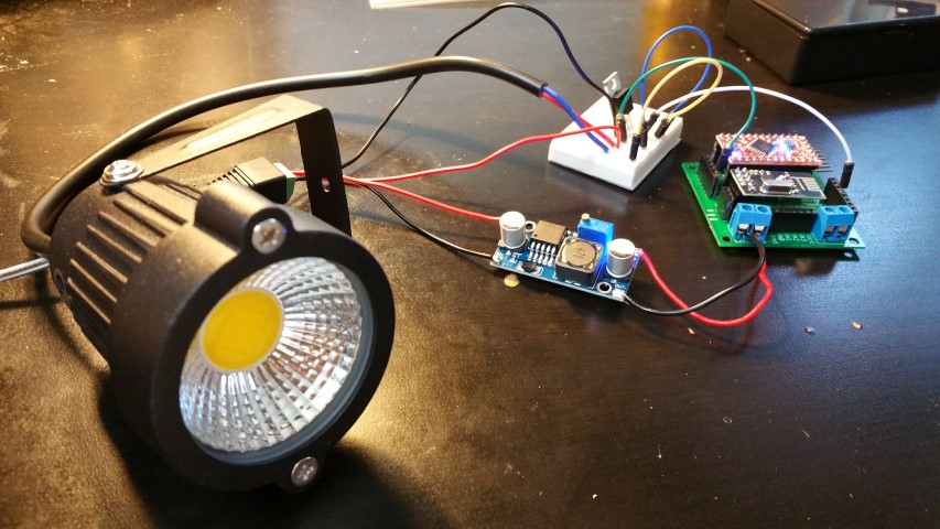
Connected the whole thing up....working nicely.
Though I do see a flicker when I try to dim it...
-
Figured out the flicker issue, it was the power supply. I was using a puny 750mA wall wart which could handle the PWM duty cycle. Once I put my hefty 12V power supply, its behaving fine.
I built a perfboard and the FET and was able to fit everything in a plastic DIY box from ebay.
How do I weatherize this because this will be outside exposed to elements? Also thinking of making some holes in the box to vent out some heat.
Whats the best way to do this?
-AM