CNC PCB milling
-
Sorry for all the noob questions, but maybe others can learn from this as well.
How do I know when a bit has become worn-out enough that it should be replaced with a newer, sharper bit? Does the software provide any feedback (e.g. maybe the motors are drawing more current than expected due to dullness)?
Or do you just wait for a bit to completely fail (i.e. snap or shatter), then insert a new one, and then re-run the job from the beginning when that bit was first used?
Also, do you have a particular test board you like to use to check out the system and see if it's running up to snuff? i.e. something that would challenge the system to surface problems in advance of trying it on a a more serious board.
And is feedrate arrived at purely by trial and error, or are there good magic numbers to use for that? Since we're running the same system, maybe I could use your magic numbers (i.e. the hardware-specific constants which must be entered into the software)? If so, what are they?
@neverdie I'm saving up some money for a CNC as well and I would love if you have time to document your process. Might be to much to ask but I guess many newbie errors could be avoided. I know there are some on YouTube but I have not found any which address the questions we have had above in this thread.
-
Sorry for all the noob questions, but maybe others can learn from this as well.
How do I know when a bit has become worn-out enough that it should be replaced with a newer, sharper bit? Does the software provide any feedback (e.g. maybe the motors are drawing more current than expected due to dullness)?
Or do you just wait for a bit to completely fail (i.e. snap or shatter), then insert a new one, and then re-run the job from the beginning when that bit was first used?
Also, do you have a particular test board you like to use to check out the system and see if it's running up to snuff? i.e. something that would challenge the system to surface problems in advance of trying it on a a more serious board.
And is feedrate arrived at purely by trial and error, or are there good magic numbers to use for that? Since we're running the same system, maybe I could use your magic numbers (i.e. the hardware-specific constants which must be entered into the software)? If so, what are they?
@neverdie said in CNC PCB milling:
Sorry for all the noob questions, but maybe others can learn from this as well.
How do I know when a bit has become worn-out enough that it should be replaced with a newer, sharper bit?
How do you know when you shaver is going dull? You inspect the result using a maginfying glass or microscope (I have at least one of my usb microscopes next to the cnc, if the edges are getting worse I replace the bit
Does the software provide any feedback (e.g. maybe the motors are drawing more current than expected due to dullness)?
No, maybe when milling metal that would be detectable, for pcb milling the forces are very lowOr do you just wait for a bit to completely fail (i.e. snap or shatter), then insert a new one, and then re-run the job from the beginning when that bit was first used?
yes, just to mention you can resharpen the bit. If it's Ti coated you lose that, but normal bits can be resharpened using a stone, then tested for width since you change that when resahrpeningAlso, do you have a particular test board you like to use to check out the system and see if it's running up to snuff? i.e. something that would challenge the system to surface problems in advance of trying it on a a more serious board.
LEARN GCODE, I can not emphasize it enough, half an hour taken to understand 5-10 commands is all it takes, G90/G91/G92; G0/G1 is all you need! Than you can take your time and write small scripts, for eg. that do a zigzag like pattern with passes at increasing distances and you can check your actual bit sizeAnd is feedrate arrived at purely by trial and error, or are there good magic numbers to use for that?
Mostly yes, read the comment above, and your script just change the F parameter of the G1 moves and see for yourself using your microscope which speed yelds the best results
Since we're running the same system, maybe I could use your magic numbers (i.e. the hardware-specific constants which must be entered into the software)? If so, what are they?
**Steps/mm for a certain machine is the only hard-coded magic number, if you don't know it you can throw the machine into trash for milling wrong dimensions!!!!! (or use a caliper and calculate that number yourself, but don't tell that to anyone) ** -
Example script:
Manually written gcode for good feedrate discoveryDON'T run it on your machine untill you understand exactly what each line of code does!
G21 (Unit of Measure - millimeter) G90 (Set to Absolute Positioning) G94 (Feed Mode - Units per minute) F200.00 (feed rate mm/min) G00 Z0.5000 M03 (start spindle) G4 P1 (Dwell/Pause) G01 Z-0.1000 G4 P0.5 (Dwell/Pause) (test 1) F200.00 (feed rate mm/min) G01 X10.0000Y5.0000 G01 X0.0000Y10.0000 F400.00 (feed rate mm/min) G01 X10.0000Y15.0000 G01 X0.0000Y20.0000 F600.00 (feed rate mm/min) G01 X10.0000Y25.0000 G01 X0.0000Y30.0000 F800.00 (feed rate mm/min) G01 X10.0000Y35.0000 G01 X0.0000Y40.0000 F1000.00 (feed rate mm/min) G01 X10.0000Y45.0000 G01 X0.0000Y50.0000 (test2) G00 Z1.5000 (raise spindle) G00 X5Y0 (go right) G01 Z-0.1000 (down spindle) G4 P0.5 (Dwell/Pause) F1200.00 (feed rate mm/min) G01 X15.0000Y5.0000 G01 X5.0000Y10.0000 F1400.00 (feed rate mm/min) G01 X15.0000Y15.0000 G01 X5.0000Y20.0000 F1600.00 (feed rate mm/min) G01 X15.0000Y25.0000 G01 X5.0000Y30.0000 F1800.00 (feed rate mm/min) G01 X15.0000Y35.0000 G01 X5.0000Y40.0000 F2000.00 (feed rate mm/min) G01 X15.0000Y45.0000 G01 X5.0000Y50.0000 G00 Z1.5000 G00 X0Y0 M05 (stop spindle) -
Manually written gcode to determine milling bit width
DON'T run it on your machine untill you understand exactly what each line of code does!
G21
G90
G94
F1400.00
G00 Z0.5000
M03
G4 P1
G01 Z-0.1000
G4 P0.5

(test 0.1mm)
G01 X0.0000Y5.0000
G01 X0.1000Y5.0000
G01 X0.1000Y0.0000
G01 X0.2000Y0.0000

G01 X0.2000Y5.0000
G01 X0.3000Y5.0000
G01 X0.3000Y0.0000
G01 X0.4000Y0.0000

G01 X0.4000Y5.0000
G01 X0.5000Y5.0000
G01 X0.5000Y0.0000
G01 X0.6000Y0.0000

G01 X1.6000Y0.0000

(test 0.2mm)
G01 X1.6000Y5.0000
G01 X1.8000Y5.0000
G01 X1.8000Y0.0000
G01 X2.0000Y0.0000

G01 X2.0000Y5.0000
G01 X2.2000Y5.0000
G01 X2.2000Y0.0000
G01 X2.4000Y0.0000

G01 X2.4000Y5.0000
G01 X2.6000Y5.0000
G01 X2.6000Y0.0000
G01 X2.8000Y0.0000

G01 X3.8000Y0.0000

(test 0.3mm)
G01 X3.8000Y5.0000
G01 X4.1000Y5.0000
G01 X4.1000Y0.0000
G01 X4.4000Y0.0000

G01 X4.4000Y5.0000
G01 X4.7000Y5.0000
G01 X4.7000Y0.0000
G01 X5.0000Y0.0000

G01 X5.0000Y5.0000
G01 X5.3000Y5.0000
G01 X5.3000Y0.0000
G01 X5.6000Y0.0000

G01 X6.6000Y0.0000

(test 0.4mm)
G01 X6.6000Y5.0000
G01 X7.0000Y5.0000
G01 X7.0000Y0.0000
G01 X7.4000Y0.0000

G01 X7.4000Y5.0000
G01 X7.8000Y5.0000
G01 X7.8000Y0.0000
G01 X8.2000Y0.0000

G01 X8.2000Y5.0000
G01 X8.6000Y5.0000
G01 X8.6000Y0.0000
G01 X9.0000Y0.0000

G01 X10.0000Y0.0000

(test 0.5mm)
G01 X10.0000Y5.0000
G01 X10.5000Y5.0000
G01 X10.5000Y0.0000
G01 X11.0000Y0.0000

G01 X11.0000Y5.0000
G01 X11.5000Y5.0000
G01 X11.5000Y0.0000
G01 X12.0000Y0.0000

G01 X12.0000Y5.0000
G01 X12.5000Y5.0000
G01 X12.5000Y0.0000
G01 X13.0000Y0.0000

G01 X14.0000Y0.0000

(test 0.6mm)
G01 X14.0000Y5.0000
G01 X14.6000Y5.0000
G01 X14.6000Y0.0000
G01 X15.2000Y0.0000

G01 X15.2000Y5.0000
G01 X15.8000Y5.0000
G01 X15.8000Y0.0000
G01 X16.4000Y0.0000

G01 X16.4000Y5.0000
G01 X17.0000Y5.0000
G01 X17.0000Y0.0000
G01 X17.6000Y0.0000

G01 X18.6000Y0.0000

(test 0.7mm)
G01 X18.6000Y5.0000
G01 X19.3000Y5.0000
G01 X19.3000Y0.0000
G01 X20.0000Y0.0000

G01 X20.0000Y5.0000
G01 X20.7000Y5.0000
G01 X20.7000Y0.0000
G01 X21.4000Y0.0000

G01 X21.4000Y5.0000
G01 X22.1000Y5.0000
G01 X22.1000Y0.0000

G00 Z1.5000
G00 X0Y0
M05
When you see copper "silvers" between the passes you know your bit is 0.1mm narrower than the corresponding width :sunglasses:
-
Manually written gcode to determine milling bit width
DON'T run it on your machine untill you understand exactly what each line of code does!
G21
G90
G94
F1400.00
G00 Z0.5000
M03
G4 P1
G01 Z-0.1000
G4 P0.5

(test 0.1mm)
G01 X0.0000Y5.0000
G01 X0.1000Y5.0000
G01 X0.1000Y0.0000
G01 X0.2000Y0.0000

G01 X0.2000Y5.0000
G01 X0.3000Y5.0000
G01 X0.3000Y0.0000
G01 X0.4000Y0.0000

G01 X0.4000Y5.0000
G01 X0.5000Y5.0000
G01 X0.5000Y0.0000
G01 X0.6000Y0.0000

G01 X1.6000Y0.0000

(test 0.2mm)
G01 X1.6000Y5.0000
G01 X1.8000Y5.0000
G01 X1.8000Y0.0000
G01 X2.0000Y0.0000

G01 X2.0000Y5.0000
G01 X2.2000Y5.0000
G01 X2.2000Y0.0000
G01 X2.4000Y0.0000

G01 X2.4000Y5.0000
G01 X2.6000Y5.0000
G01 X2.6000Y0.0000
G01 X2.8000Y0.0000

G01 X3.8000Y0.0000

(test 0.3mm)
G01 X3.8000Y5.0000
G01 X4.1000Y5.0000
G01 X4.1000Y0.0000
G01 X4.4000Y0.0000

G01 X4.4000Y5.0000
G01 X4.7000Y5.0000
G01 X4.7000Y0.0000
G01 X5.0000Y0.0000

G01 X5.0000Y5.0000
G01 X5.3000Y5.0000
G01 X5.3000Y0.0000
G01 X5.6000Y0.0000

G01 X6.6000Y0.0000

(test 0.4mm)
G01 X6.6000Y5.0000
G01 X7.0000Y5.0000
G01 X7.0000Y0.0000
G01 X7.4000Y0.0000

G01 X7.4000Y5.0000
G01 X7.8000Y5.0000
G01 X7.8000Y0.0000
G01 X8.2000Y0.0000

G01 X8.2000Y5.0000
G01 X8.6000Y5.0000
G01 X8.6000Y0.0000
G01 X9.0000Y0.0000

G01 X10.0000Y0.0000

(test 0.5mm)
G01 X10.0000Y5.0000
G01 X10.5000Y5.0000
G01 X10.5000Y0.0000
G01 X11.0000Y0.0000

G01 X11.0000Y5.0000
G01 X11.5000Y5.0000
G01 X11.5000Y0.0000
G01 X12.0000Y0.0000

G01 X12.0000Y5.0000
G01 X12.5000Y5.0000
G01 X12.5000Y0.0000
G01 X13.0000Y0.0000

G01 X14.0000Y0.0000

(test 0.6mm)
G01 X14.0000Y5.0000
G01 X14.6000Y5.0000
G01 X14.6000Y0.0000
G01 X15.2000Y0.0000

G01 X15.2000Y5.0000
G01 X15.8000Y5.0000
G01 X15.8000Y0.0000
G01 X16.4000Y0.0000

G01 X16.4000Y5.0000
G01 X17.0000Y5.0000
G01 X17.0000Y0.0000
G01 X17.6000Y0.0000

G01 X18.6000Y0.0000

(test 0.7mm)
G01 X18.6000Y5.0000
G01 X19.3000Y5.0000
G01 X19.3000Y0.0000
G01 X20.0000Y0.0000

G01 X20.0000Y5.0000
G01 X20.7000Y5.0000
G01 X20.7000Y0.0000
G01 X21.4000Y0.0000

G01 X21.4000Y5.0000
G01 X22.1000Y5.0000
G01 X22.1000Y0.0000

G00 Z1.5000
G00 X0Y0
M05
When you see copper "silvers" between the passes you know your bit is 0.1mm narrower than the corresponding width :sunglasses:
@executivul Good stuff! I imagine I'll get there eventually, but on Day 1 I'd rather start with some reasonable magic constants that at least put me in the ballpark.
-
@neverdie I'm saving up some money for a CNC as well and I would love if you have time to document your process. Might be to much to ask but I guess many newbie errors could be avoided. I know there are some on YouTube but I have not found any which address the questions we have had above in this thread.
@sundberg84 said in CNC PCB milling:
@neverdie I'm saving up some money for a CNC as well and I would love if you have time to document your process. Might be to much to ask but I guess many newbie errors could be avoided. I know there are some on YouTube but I have not found any which address the questions we have had above in this thread.
Yes, that's what I'm attempting to do on this thread. :)
-
JFYI: CNC 2418 assembly by me :)
https://www.youtube.com/watch?v=T2_18-ObvP0
I'll try to make a blog to describe the whole pcb cnc milling, tools etc, as well as other diy projects. I'll let you know if there is any notable progress...
-
Best way to get rid of the dust seems to be not making dust to start with.
Enjoy!
https://youtu.be/PpXG1X9yoxs -
Best way to get rid of the dust seems to be not making dust to start with.
Enjoy!
https://youtu.be/PpXG1X9yoxs@executivul Which car shampoo?
How well does it work? Would it work better if you flooded it a bit more so that it was sitting, say, a couple mm under shampoo solution?
-
I suppose your etching bit might last longer too, since maybe the liquid would help cool it.
-
Unfortunately I can not disclose this secret recipe, all I can tell you is that s some cationic surfactant mixed with some dihydrogen peroxide :sunglasses:
To be honest I don't know the brand, I've first tried liquid soap undiluted but was to thick and was gathering around the bit like a small tornado and splashing everywhere, decided to add some water and went looking for a spray bottle, found one with some handwriting "car shampoo", it is thicker than plain water, but not as thick as liquid soap, so it might be diluted, I still have some for a few more boards then I'll go by trial and error with dish/hand/car wash and water.
So much better not to have windows open at 0C(32F) and the vacuum howling. Only the 2.0mm endmill still creates dust, normal engraving and drilling do not.
Don't forget to mill on acrylic/plastic as mdf will swell if wet. -
Looks like my CNC2418 is on track to be delivered this Monday. It has already cleared customs.
So, since it will be arriving well ahead of all the various bits and such, I'm guessing that just a few etching bits will be enough to get me started and confirm whether my machine can route 6 mil isolation.
The kit itself includes 0.1mm bits (Diameter: 3.175mm tip: 0.1mm length: 30mm).
-
-
@andrew said in CNC PCB milling:
@neverdie so, I expect your first boards tomorrow :)
But wait, I'm still waiting for the magic numbers from you. :) Otherwise, I'll be all dressed with nowhere to go.
-
@andrew said in CNC PCB milling:
@neverdie so, I expect your first boards tomorrow :)
But wait, I'm still waiting for the magic numbers from you. :) Otherwise, I'll be all dressed with nowhere to go.
@neverdie once the assembly is done, you should adjust the stepper drivers' current limiting as well.
it is pololu a4988, you can find the corresponding details here:
https://www.pololu.com/product/1182then, it is always good idea to have the basic settings exported from the board, just in case... you can do it by "$$" command sent from the g code sender gui or directly from the serial terminal.
currently I use the following settings, the machine might be able to create nice results with higher feed rates, but I did not have enough time to test it and I sticked to the current working config.
isolation routing with 2001 bits:
- z cut: -0.05mm
- feed rate: 200
you can calculate the V carving bit's tool width for the given milling depth with the following formula:
tan(bit angle/2) * milling depth * 2 + bit's end width
for excel formula the bit angle should be provided in radians, so it should look like this
tan(radians(bit angle/2)) * milling depth * 2 + bit's end widthedge cut or hole milling with the 0.8mm endmill:
- feed rate: 170
- z cut: -1.7mm
- multi depth, depth/pass: 0.2mm
drilling:
- feed rate: 130
- z cut: -1.8
the spindle should be 1000 everywhere.
most probably your board will not have a bootloader, so it will not be possible to update the firmware via usb serial connection (with avrdude), but it is worth to try it. for me it did not work, so I traced back the MCU pins to the pin rows and used ISP to upgrade the firmware to grbl v1.1f (the board will come with 0.9j if I remember correctly). do not forget to export the gerber settings before you upgrade the firmware, as it will loose those, and you have to re-assign the given values again, after the update.
the ISP pinout (from the pin row's top left corner):
Reset -> pin 2
SCK -> pin 3
MISO -> pin 12
MOSI -> pin 135v -> pin1
gnd-> bottom row(!) e.g. pin 1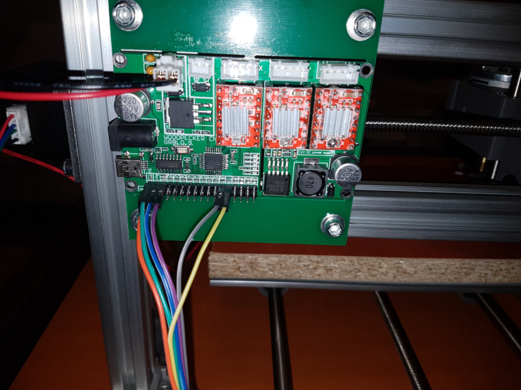
-
The assembly instructions came as a file on a mini CD. Attached for anyone who is interested.
[0_1513463653125_2418-Assembly instructions - English.doc](Uploading 100%)
Hmmm.. I guess the forum only lets me upload photos. Sorry.