CNC PCB milling
-
I ordered 3 of these closed loop mechaduino clone controllers that utilize 12-bit encoders:
https://www.aliexpress.com/item/32917408111.html?spm=a2g0s.9042311.0.0.44f74c4dxgjrOvThe uStepper hardware specs are better, at least on paper: 16-bit encoders and higher voltages, but at 4x the price, plus even more cash if you want an equivalent OLED add-on with buttons. For sure Ustepper's trinamic hardware is very tempting, but I'm not sure how solid the uStepper firmware currently is, whereas the mechaduino firmware has been tested for a few years now. I also get the impression, perhaps incorrectly, that the ustepper documentation is comparatively sparse right now. So, for all those reasons, I chose mechaduino over Ustepper. Maybe later, somewhere down the road, I'll give Ustepper a try.
ETA for the mechaduino's is about a month from now. I'll report back after I've received them and given them a try.
Meanwhile, on an unrelated topic, I was finally able to test one of the tiny diameter endmills:
https://www.amazon.com/gp/product/B06WRWLK79/ref=ppx_yo_dt_b_asin_title_o05_s00?ie=UTF8&psc=1
and Wow! It works great. My first impression is that this is the solution I've been looking for: just set the cutting depth to be "more than enough" and you can isolation cut all the traces in one pass while keeping the desired trace width. Much faster and easier to use than v-bits, IMHO. -
Anyone else out there using CNC to make their own PCB's? After taking a break from it for a while, I'm going to take another stab at it, now with the benefit of fresh eyes. Right off the bat I'm making a few changes:
- Flattening a space for the PCB on the sacrificial board so that little to no bed leveling will be required:
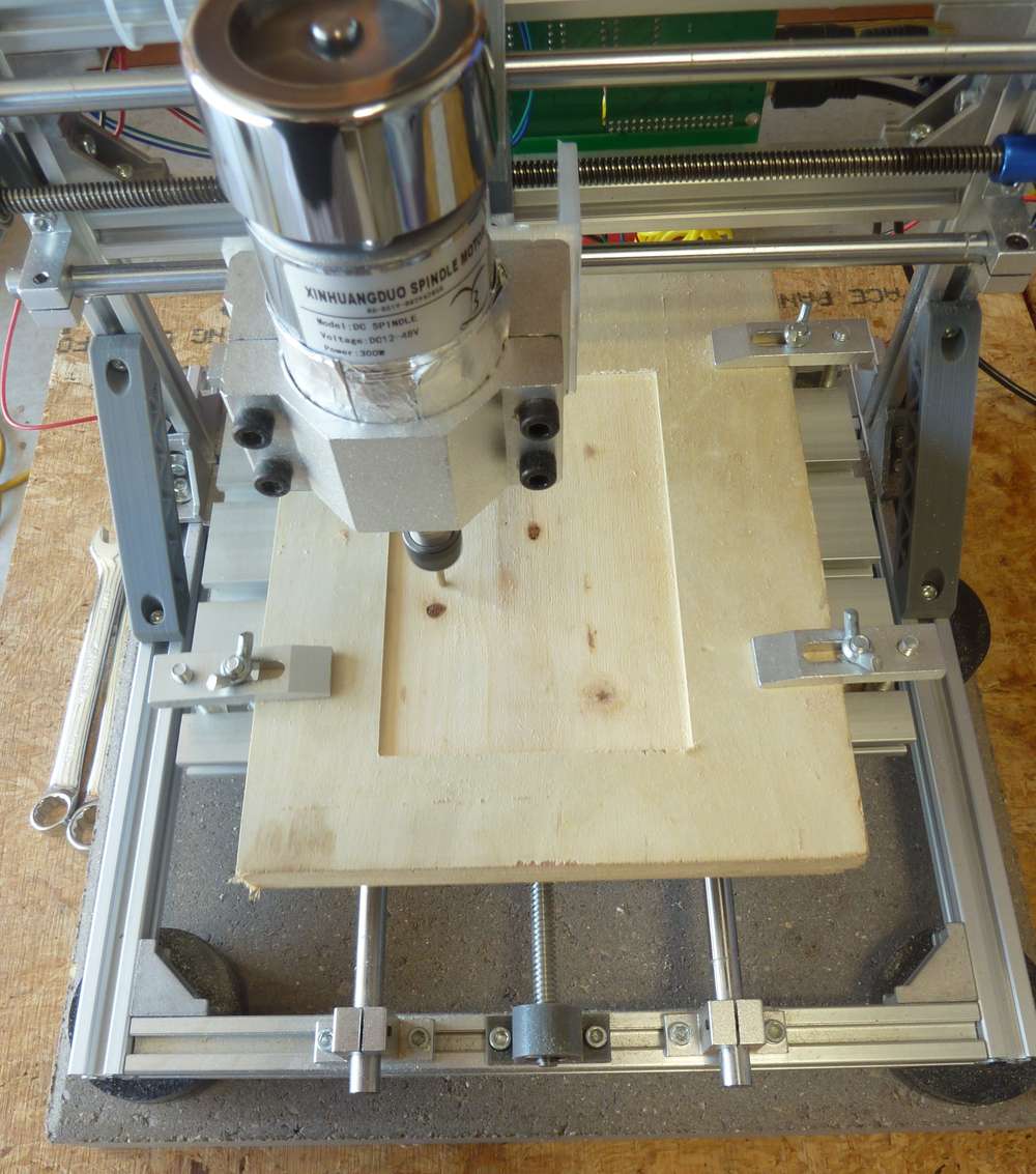
- As seen in the photo just above, using a concrete paver to stabilize the platform. This is a common tactic used in 3D printers.
- Mounting the printer on non-skid pucks (also shown in the photo) to guarantee that the CNC doesn't slide around.
- Using FR-1 instead of FR-4 as the substrate for the copper clad PCB.
- As already mentioned in the post just above, using end-mill bits instead of v-bits to accomplish the etching.
- Oh, and yes, I replaced the spindle I was previously using with this upgraded, more powerful spindle.
- Using a stronger double-sided tape ("Nitto Tape") to hold the PCB in position while the PCB is being etched by the CNC. Actually, I'm not unsure as to whether it's stronger than the double sided golf grip tape I was using previously, but I'm trying it today, so I'll soon have a basis on which to gauge it.
- Laying around somewhere I have some TMC drivers, and when I find them I'll use them to upgrade the rudimentary GRBL controller that came with the original CNC kit. Not sure if it will yield any improvements, but, meh, seems like it's worth trying.
- I've switched to a domestic fabricator of blank PCBs that I'll use instead of the Aliexpress ones. I don't know whether it will make a difference, but the quality does seem to be higher, and I can get them with thicker substrates than what I can find on aliexpress.
- I switched to a metal spindle mount.
I've already noticed one anomaly that I hadn't noticed previously, which is that if I use Flatcam to set the depth of cut to 1.5875mm (equals 1/16 of an inch), then if I do it in 4 passes (where the first pass is at 0.5mm depth, the second at 1.0mm depth, the third at 1.5mm depth, and finally the last pass at 1.5875mm, I end up getting a shallower depth of cut than if I were to later do a depth of cut of 1.5875mm in just one pass. Not sure if this is caused by an error in chillipepr, the gerbal controller, or the stepper missing steps.
Meanwhile, software seems to have improved since the last time I was using it, so I'm looking forward to trying it again as well as new alternatives. Anyone here have any favorites?
@NeverDie I do not yet have a CNC mill.
If ever I wanted to make a PCB I used photosensitive PCB. Etching goes very well. And I also discovered that waiting a few weeks for well made pcb's is usually worth it.
But I pretty much read this whole topic. I am still interested by your experiences. So thank you for sharing. - Flattening a space for the PCB on the sacrificial board so that little to no bed leveling will be required:
-
Anyone else out there using CNC to make their own PCB's? After taking a break from it for a while, I'm going to take another stab at it, now with the benefit of fresh eyes. Right off the bat I'm making a few changes:
- Flattening a space for the PCB on the sacrificial board so that little to no bed leveling will be required:
- As seen in the photo just above, using a concrete paver to stabilize the platform. This is a common tactic used in 3D printers.
- Mounting the printer on non-skid pucks (also shown in the photo) to guarantee that the CNC doesn't slide around.
- Using FR-1 instead of FR-4 as the substrate for the copper clad PCB.
- As already mentioned in the post just above, using end-mill bits instead of v-bits to accomplish the etching.
- Oh, and yes, I replaced the spindle I was previously using with this upgraded, more powerful spindle.
- Using a stronger double-sided tape ("Nitto Tape") to hold the PCB in position while the PCB is being etched by the CNC. Actually, I'm not unsure as to whether it's stronger than the double sided golf grip tape I was using previously, but I'm trying it today, so I'll soon have a basis on which to gauge it.
- Laying around somewhere I have some TMC drivers, and when I find them I'll use them to upgrade the rudimentary GRBL controller that came with the original CNC kit. Not sure if it will yield any improvements, but, meh, seems like it's worth trying.
- I've switched to a domestic fabricator of blank PCBs that I'll use instead of the Aliexpress ones. I don't know whether it will make a difference, but the quality does seem to be higher, and I can get them with thicker substrates than what I can find on aliexpress.
- I switched to a metal spindle mount.
I've already noticed one anomaly that I hadn't noticed previously, which is that if I use Flatcam to set the depth of cut to 1.5875mm (equals 1/16 of an inch), then if I do it in 4 passes (where the first pass is at 0.5mm depth, the second at 1.0mm depth, the third at 1.5mm depth, and finally the last pass at 1.5875mm, I end up getting a shallower depth of cut than if I were to later do a depth of cut of 1.5875mm in just one pass. Not sure if this is caused by an error in chillipepr, the gerbal controller, or the stepper missing steps.
Meanwhile, software seems to have improved since the last time I was using it, so I'm looking forward to trying it again as well as new alternatives. Anyone here have any favorites?
Hey @NeverDie, everyone,
It is good to see how this thread developed over the time and you guys are enjoying the PCB milling.
Unfortunately I had many other responsibilities and was super busy, so a lot from my projects had to be postponed. Nevertheless I'm still working with my CNC.A few days ago I replaced the spindle to a laser module to make same plywood engraving, and the original spindle motor holder (the 3D printed stuff) broke during the unscrew...
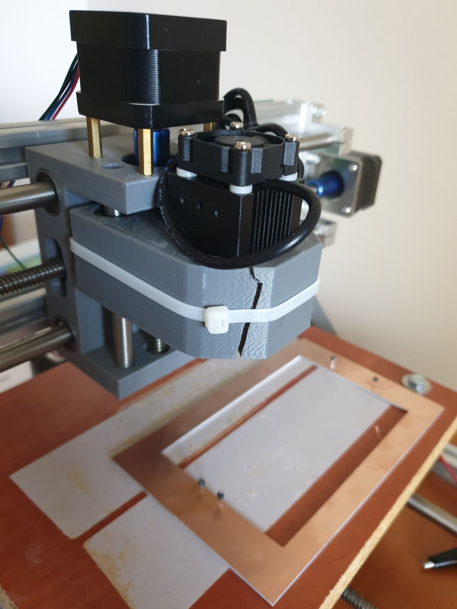
I managed to fix the laser module with cable tie. :)
It is ok for the laser, but of course not for the spindle and for the PCB milling.
Replacement parts are available mostly in packages (e.g. https://www.ebay.com/itm/Replacement-Parts-DIY-Kit-for-CNC-1610-2418-3018-Spindle-Holder-Screw-Polish-Pod/112382449851), but it is possible to print your own version too.
Some guys already came up with an enhanced design, such as https://www.thingiverse.com/thing:3586273I already wanted to make an upgrade on the CNC, so I came to a conclusion, that I will fix the broken part with a custom 3D printed one, then sell the machine.
I already ordered my new toy, a CNC3020T (EUR 325 + shipping EUR 25):
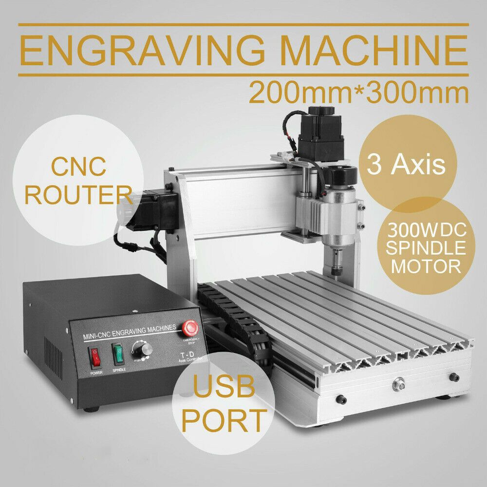
Well, I hesitated a lot and almost bought a CNC3040Z-DQ (bigger, better, ball screw), but as currently I really don't have enough space for it (and to be honest, no reason to buy a better/bigger) I sticked with the 3020T. The quality I achieved with my 2418 will be definitely reproducible and this is enough.
I just read the endmill isolation routing posts. Interesting stuff.
I'm curious whether you can use smaller ones to deal with the 6mil/6mil trace/isolation sizes.Happy milling and cheers!
- Flattening a space for the PCB on the sacrificial board so that little to no bed leveling will be required:
-
Hey @NeverDie, everyone,
It is good to see how this thread developed over the time and you guys are enjoying the PCB milling.
Unfortunately I had many other responsibilities and was super busy, so a lot from my projects had to be postponed. Nevertheless I'm still working with my CNC.A few days ago I replaced the spindle to a laser module to make same plywood engraving, and the original spindle motor holder (the 3D printed stuff) broke during the unscrew...
I managed to fix the laser module with cable tie. :)
It is ok for the laser, but of course not for the spindle and for the PCB milling.
Replacement parts are available mostly in packages (e.g. https://www.ebay.com/itm/Replacement-Parts-DIY-Kit-for-CNC-1610-2418-3018-Spindle-Holder-Screw-Polish-Pod/112382449851), but it is possible to print your own version too.
Some guys already came up with an enhanced design, such as https://www.thingiverse.com/thing:3586273I already wanted to make an upgrade on the CNC, so I came to a conclusion, that I will fix the broken part with a custom 3D printed one, then sell the machine.
I already ordered my new toy, a CNC3020T (EUR 325 + shipping EUR 25):
Well, I hesitated a lot and almost bought a CNC3040Z-DQ (bigger, better, ball screw), but as currently I really don't have enough space for it (and to be honest, no reason to buy a better/bigger) I sticked with the 3020T. The quality I achieved with my 2418 will be definitely reproducible and this is enough.
I just read the endmill isolation routing posts. Interesting stuff.
I'm curious whether you can use smaller ones to deal with the 6mil/6mil trace/isolation sizes.Happy milling and cheers!
Hi Andrew!
Great to hear from you and your updates. :-)
@andrew said in CNC PCB milling:
I'm curious whether you can use smaller ones to deal with the 6mil/6mil trace/isolation sizes.
Yes, I'm wondering the same thing. There's reason to be hopeful that it can be done: I've seen a number of 0.1mm end mills for sale, and that's roughly the the bit diameter that would be needed. After I upgrade my stepper motors to higher torque models, and after I upgrade them even further to be closed loop, I'd like to give it a try. Fine pitched etchings like that would probably also greatly benefit if solder mask could be applied afterward, and so I'm hoping to learn how do that as well:
https://www.amazon.com/MECHANIC-Prevent-Corrosive-Soldering-Welding/dp/B076YPKBKL
Join the fun! With your new machine already on the way, you may be ready to give it a try before me. :sunglasses:
When you get a chance, please do let us know how you like your new CNC. It looks a lot sturdier than the CNC that you will soon be selling.
-
One more thing worth mentioning: This guy has, I think, a correct insight into why auto-leveling may not work as well in the real world as it theoretically should:
Blank PCB material is not as rigid as it appears, depending on its size and how it was stored (not to mention how you mount it) there will be some bowing which results in a curved surface under your engraver.
Unfortunately, the probing process doesn't put enough pressure on the board to push it down while the actual engraving process will. This means you will get shallow cuts even with an autolevelling process.
The trick is to ensure that the probe pushes the board down to it's fully flat level before measuring the height at that point. My solution was to put a small ball on the spindle that is 2mm lower than the probe tip - as the probe moves downwards the ball pushes the PCB to the underlying bed and compresses before the probe makes contact. This gives you a far more accurate depth reading.
https://blog.thegaragelab.com/seven-pcb-milling-tips/His solution looks like this:

which looks as though it could be improved upon. -
Recent strategy was to do multiple overlapping passes with a narrow diameter bit to get lots of isolation. It nominallly worked, but it consumed a lot of machine time. So, now testing a new strategy, which is to first do one bulk isolation with a wide bit and then do one final pass with a narrow bit to clean out whatever copper remains near the traces. Though it does require a tool change, in theory it should be faster.
-
I have found a YouTube channel that has a few video's about using the 3018 CNC for PCB milling.
They winked a bit at the Wegstr promotional video.
But they seem to get good quality. They also have better video's explaining the steps.
-
Can anyone here explain the appeal of Mach3 in the year 2020? The premise seems to be: don't use stepper driver hardware (e.g. Trinamics) and don't use a motion controller, but instead do all the stepper motor control directly from a PC by bit-banging pins on a parallel port in real-time!? How is that a good idea, and why is it advantageous? I understand how maybe back in the day that was perhaps the most affordable way to do it, but these days? I just don't get it.
@NeverDie Just get any Atmega328 board (Uno, Nano) and flash grbl 1.1f and wire it to whatever drivers you have (now I'm using hybrid closed loop servos, but I've used TB6560 in the past).
I use OpenCNCPilot, it has autolevel, and a lot of other useful functions: simplify, arc to lines, split long lines, etc. I mainly use it for splitting long lines, as a long move doesn't account for the board topography (local highs and lows), by splitting the line accordingly to the detail needed (5mm for dip, 2-3mm for smaller smd boards) I get a much better engraving. Also the autoloevel grid size and step setting is very simple. -
@NeverDie Just get any Atmega328 board (Uno, Nano) and flash grbl 1.1f and wire it to whatever drivers you have (now I'm using hybrid closed loop servos, but I've used TB6560 in the past).
I use OpenCNCPilot, it has autolevel, and a lot of other useful functions: simplify, arc to lines, split long lines, etc. I mainly use it for splitting long lines, as a long move doesn't account for the board topography (local highs and lows), by splitting the line accordingly to the detail needed (5mm for dip, 2-3mm for smaller smd boards) I get a much better engraving. Also the autoloevel grid size and step setting is very simple.Hi executivul! Great to hear from you again.
@executivul said in CNC PCB milling:
@NeverDie Just get any Atmega328 board (Uno, Nano) and flash grbl 1.1f and wire it to whatever drivers you have (now I'm using hybrid closed loop servos, but I've used TB6560 in the past).
On Aliexpress I notice there are these drivers (one per axis) that it sounds as though you are using. Some of them (usually blue) are self-described as "Hybrid", whereas others (often Green or some other color) are self-described as "closed loop." I haven't tried either one, but I get the impression that the "Hybrid" drivers function closed loop as well, and it sounds as though that is what you are doing. If that is the case, what, if any, functional difference is there between the self-described "hybrid" drivers and the self-described "closed-loop" drivers? I assume you know what I'm referring to, but if not, let me know and I'll post pictures and links in order to clarify.
-
By the way, good news! Just yesterday I think I've identified the very same spring-loaded bit used very successfully by both Bantam Tools and Wegstr for removing DIY solder mask over solder pads. :grin: Details here: https://www.cnczone.com/forums/pcb-milling/408516-best-material-spoilboard-beneath-pcb-etching-best.html#post2395490
For anyone not familiar with this process, here is a demo video:
https://www.youtube.com/watch?v=vaqOFH0Te5QI'll be giving it a try once my rig is upgraded and re-tuned, because obviously the z-axis height needs to be controlled very precisely for it to work without etching off the same copper pads that I'll be trying to re-expose from under the solder mask. I suppose using 2oz copper clad might also be worth it for the wee bit of added headroom. If push comes shove, I've read that even thicker copper clad PCB is available, though off-hand I have no idea where would be a good place to buy it. From what I've read the thicker cladding is most often found in PCB's made for military applications.
Edit: Gave a quick cursory look, and both 3oz and 4oz copper clad PCB is not hard to find. Not saying it will be needed, but nice to know in case it is.
-
Time to upgrade the motion controller. The woodpecker is hopeless because it takes 12v-36v input voltage and downconverts it to 12v:

This means you can't actually drive your stepper stick at more than 12v, even though the A4988 can use up to 36v and the DRV8825 up to 45v. The TMC5160 allows up to 60v. I'm guessing the grbl board designers did this to avoid any possibility of going over the allowed voltage, which would mean fewer warrantee returns. All well and good for them, but if I'm not mistaken, it deprives the user of snappier accelerations.So, I ordered just a primitive arduino shield, and hopefully it is lacking this "feature":

The board markings do indicate the same 12-36v range, though, but I'm guessing that's there purely either as a cautionary warning for A4988 users or because that's the highest voltage that the capacitors are rated for. Given the cramped board, perhaps trace widths are a factor as well.The mechaduino driver can handle voltages up to 40v, but the mechaduino board itself was designed with 36v capacitors. The MKS-servo42a has a 30v maximum according to the design they borrowed from.
All this does make me interested in trying a TMC5160 at 60v just to see how much snappier it might be.
Unfortunately, the uStepper (http://ustepper.com/product_sheet_revB.pdf), despite using the TMC5160, doesn't take advantage of the 60v possibility. It recommends 24v input voltage, with a 30v maximum.
Good grief! Why, oh why, did they do that? Was it just to save a few pennies on component cost? Will I have to design my own board if I want high performance?
I was originally hoping for this to be a drop-in upgrade. Maybe it still is, but I'm starting to have doubts about just how much of a performance upgrade I can expect from it.
-
Reporting back: I received the el cheapo GRBL boards (above). The good news is that they don't have a buck converter getting in the way, the way the woodpecker does. The bad news is that the caps are rated at only 40v. So, I may replae them with ones rated for higher voltage. Also, there's a mysterious glass fuse soldered in the midst of it all. Not sure at what current it's rated to blow but, meh, probably high enough if the designer did his homework.
So, overall, I expect this will be an improvement over woodpecker for running GRBL at higher voltage. :-)
-
@NeverDie judging from the images, this looks like a diode instead of a fuse.
Anyway, keep up the good reading, I'm loving your posts :+1:@Yveaux said in CNC PCB milling:
@NeverDie judging from the images, this looks like a diode instead of a fuse.
Not a bad guess based on the image you were working from, but if so it's a diode with the word "FUSE" written under it:

:wink:Anyway, keep up the good reading, I'm loving your posts :+1:
Thanks for the encouragement! :-)
-
The nice thing about this particular board is that there's an easy way to levitate a fan over it to cool down the stepsticks:

-
@Yveaux said in CNC PCB milling:
@NeverDie judging from the images, this looks like a diode instead of a fuse.
Not a bad guess based on the image you were working from, but if so it's a diode with the word "FUSE" written under it:
:wink:Anyway, keep up the good reading, I'm loving your posts :+1:
Thanks for the encouragement! :-)
-
@NeverDie said in CNC PCB milling:
a diode with the word "FUSE" written under it
Got me there, but it seems to be a fuse with orientation :thinking_face:
We'll never know unless you put a multimeter on it :wink:@Yveaux said in CNC PCB milling:
@NeverDie said in CNC PCB milling:
a diode with the word "FUSE" written under it
Got me there, but it seems to be a fuse with orientation :thinking_face:
We'll never know unless you put a multimeter on it :wink:OK, I just now probed it, and it conducts with the same 0.12 ohm resistance in both directions. So, it's not a diode. Here's a closeup photo that I took for you:
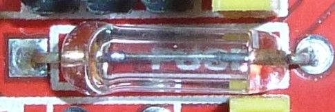
I'm going to deem it a fuse unless you have a different theory or can recognize it as something else.Anyhow, changing topics, the good news is that the electrolytic capacitors have a higher voltage rating than what I had reported earlier. They are 100uF capacitors, and upon closer inspection it says that they are rated at 50v, not 40v as I had earlier thought. That's good news, because it means they should be able to handle the 45v maximum that DRV8825 stepper drivers can tolerate. :-)
-
@Yveaux said in CNC PCB milling:
@NeverDie said in CNC PCB milling:
a diode with the word "FUSE" written under it
Got me there, but it seems to be a fuse with orientation :thinking_face:
We'll never know unless you put a multimeter on it :wink:OK, I just now probed it, and it conducts with the same 0.12 ohm resistance in both directions. So, it's not a diode. Here's a closeup photo that I took for you:
I'm going to deem it a fuse unless you have a different theory or can recognize it as something else.Anyhow, changing topics, the good news is that the electrolytic capacitors have a higher voltage rating than what I had reported earlier. They are 100uF capacitors, and upon closer inspection it says that they are rated at 50v, not 40v as I had earlier thought. That's good news, because it means they should be able to handle the 45v maximum that DRV8825 stepper drivers can tolerate. :-)
@NeverDie Did you check out the assembly instructions? There they use a fuse with a rather high current in this place :rolling_on_the_floor_laughing: :rolling_on_the_floor_laughing: :rolling_on_the_floor_laughing:
The explanation why it is polarized is because in fact, it used to be a diode in older revisions, check out Step 7 here.