CNC PCB milling
-
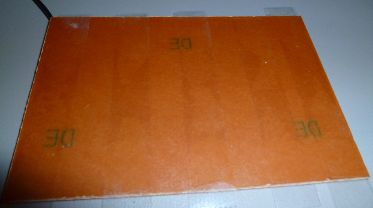
I found these copper clad boards that seem to be made out of bakelite (?) rather than fiberglass. So, hopefully not the same level of toxic dust concern as with FR4's.
I double sided taped the non-copper side:
and soldered a ground wire on the copper clad side:
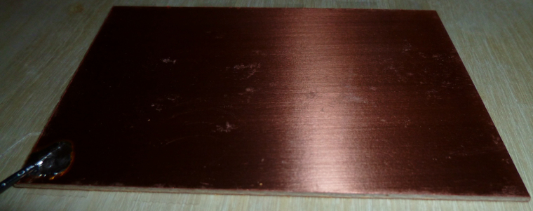
Now I'm ready for autoleveling and then my first PCB etch.
-
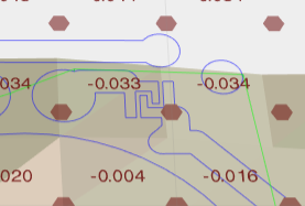
Here are the results of the autoleveling:
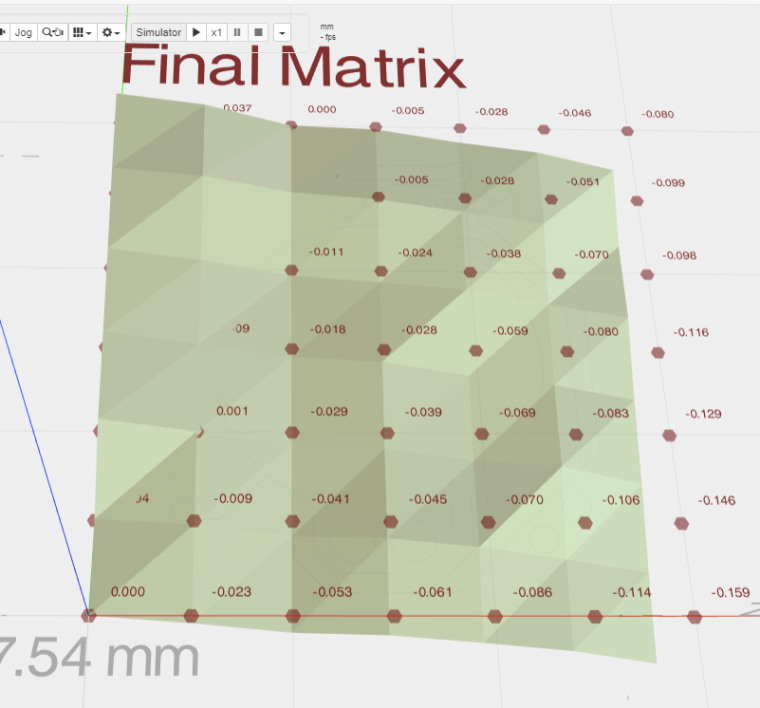
For some reason it's hard to read some of the numbers.@neverdie It looks like everything in the top right corner is above the level bed surface. which puts it above the grid that is shown. Looks like the bed is tilted.
Vera Plus running UI7 with MySensors, Sonoffs and 1-Wire devices
Visit my website for more Bits, Bytes and Ramblings from me: http://dan.bemowski.info/ -
@neverdie It looks like everything in the top right corner is above the level bed surface. which puts it above the grid that is shown. Looks like the bed is tilted.
-
LOL, except that unfortunately it did not:
OK, my bad. I hadn't sent the auto-leveled g-code to the workspace (I had thought this would be done automatically, but no), so this picture shows what would happen without auto-leveling.
I've made the change and am now re-running the job with the auto-leveled g-code.
-
Judging from the looks of the photo directly above though, it looks like quite a bit of copper wasn't removed where it needed to be. I'm guessing I will need to:
- etch to a deeper depth; and/or,
- use a finer mesh for auto-leveling; and/or
- ???
-
Etch 0.1mm. The groove between tracks also helps with soldering. I currently use 0.1mm and even 0.15 when in a hurry.
-
So, I re-ran the job over the same area with the g-code modified by auto-leveling, and this time I got a better result:
So, now I'll try it on a fresh area of the PCB, after doing a new auto-leveling.
-
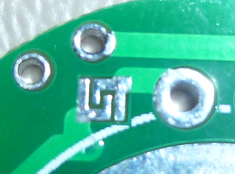
@rmtucker Good catch! Here it is in contrast to a new one:
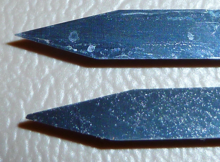
I'll replace it with the new one.
@neverdie
Just for future reference i would use a duff cutter for autolevelling then change to a good cutter to cut the job after resetting the z0.
It is so easy to smash the front of an engraving cutter when using this method for autolevelling as the machine takes a little time to stop after touching the pcb.
Just my advice anyway:relaxed: -
@neverdie
Just for future reference i would use a duff cutter for autolevelling then change to a good cutter to cut the job after resetting the z0.
It is so easy to smash the front of an engraving cutter when using this method for autolevelling as the machine takes a little time to stop after touching the pcb.
Just my advice anyway:relaxed:@rmtucker said in CNC PCB milling:
Just for future reference i would use a duff cutter for autolevelling then change to a good cutter to cut the job after resetting the z0.
What's a "duff cutter"? Did you mean "dull cutter"?
-
@rmtucker said in CNC PCB milling:
Just for future reference i would use a duff cutter for autolevelling then change to a good cutter to cut the job after resetting the z0.
What's a "duff cutter"? Did you mean "dull cutter"?
-
Argh. I ran the job, and the first cut went great. All subsequent cuts though didn't penetrate the surface:
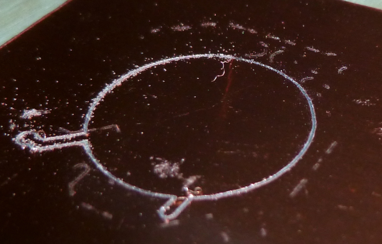
Afterward, when I checked the zero on z, I found that it was off by 0.049. That explains it, since the cut-depth was 0.05.I'll re-zero and try running the same job again.
-
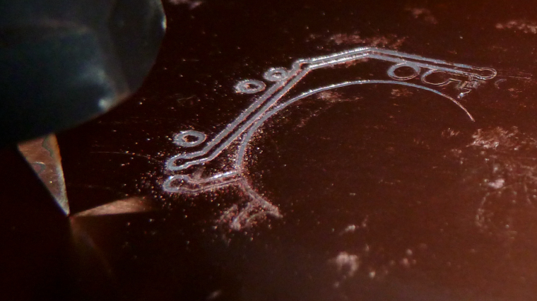
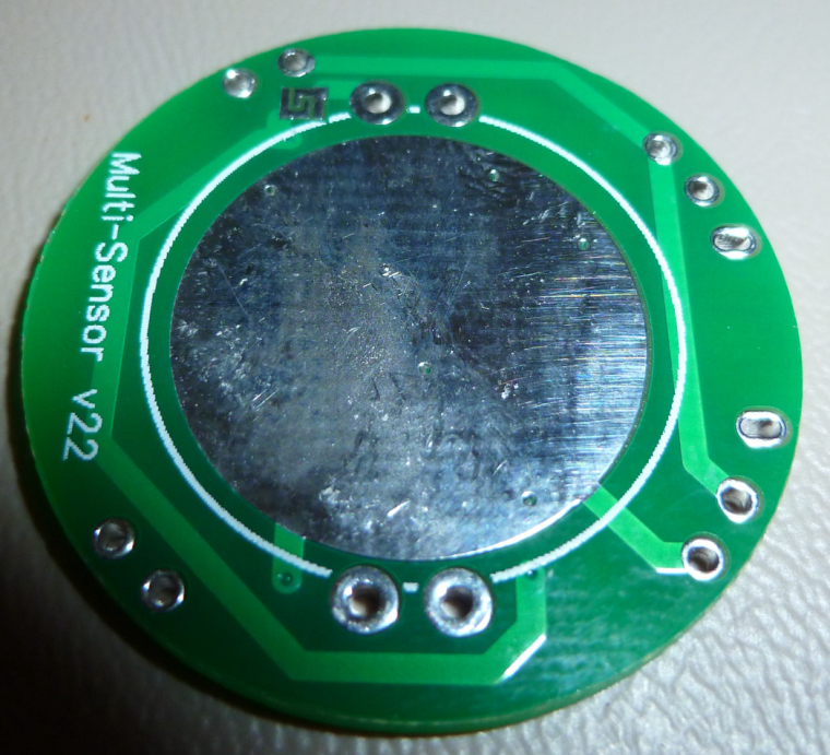
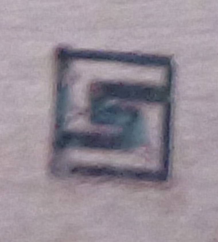
That made a much better result:
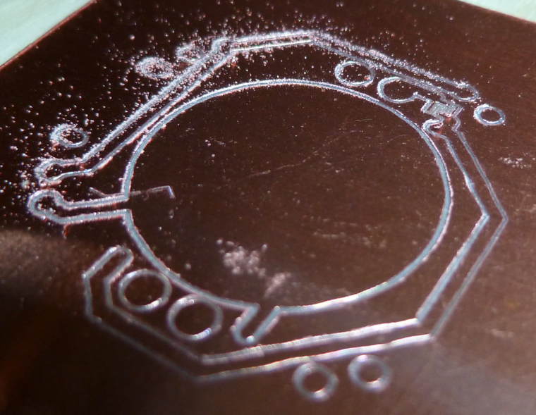
It corresponds to this as the actual PCB:
-
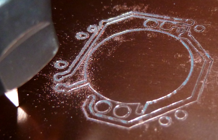
However, what's telling is that it obliterated the traces on either side of a 6 mil separation:
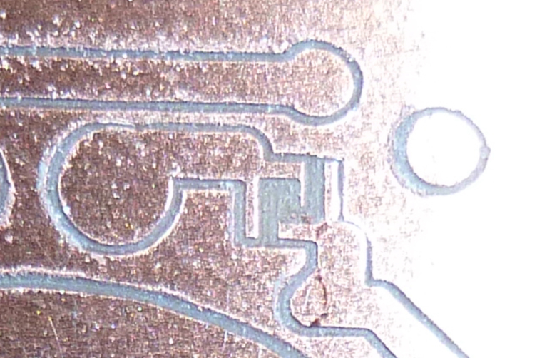
This is how it should look instead:
So, what happened?
My current hypothesis: the first cutting sheared 0.049mm off the tip of the blade, making it wider than it should be. Then, after re-zeroing, the wider blade cut too wide as it cut the traces for the solder jumper.
Is that reasonable, or is there a better hypothesis?
If it's true, then what do I do about it? Perhaps use a higher quality bit than the freebie that came with the kit?
Actually, I'm not even sure what the dimensions were on the freebie. It wasn't labeled. Perhaps it was too wide to begin with.
-
Well, to explore this more, I think I'll create a test board consisting purely of a few solder jumpers. That way I can put the focus directly on the 6 mil issue and won't be wasting time on etching that's unrelated to that.
-
Doing just a single solder jumper, with the same bit, and autoleveling every 1mm, the result is:
which is pretty close, actually. Looks like maybe the bit is a little too wide, or else there's runout which is making it appear wider than it actually is.I'll try it with a fresh bit next and see if it improves.