Any success story on LoRa(RFM95) module and MySensors?
-
@ricorico94 here is the hardware connection details, that I followed.
Gateway Sketch:
  ESP8266         RFM95
-----------      ---------
(GPIO15) CS    <--> NSS
(GPIO13) MOSI  <--> MOSI
(GPIO12) MISO  <--> MISO
(GPIO14) CLK   <--> SCK
(GPIO 5) IRQ   <--> DIO0
         GND   <--> GND
         3.3V  <--> +3.3V

Add this line on ESP8266 sketch,
#define   MY_RFM95_IRQ_PIN 5
#define   MY_RFM95_IRQ_NUM MY_RFM95_IRQ_PIN
#define   MY_RFM95_CS_PIN 15
Node Sketch:
PRO-MINI RFM95 ----------- ------- (10) SS <--> NSS (11) MOSI <--> MOSI (12) MISO <--> MISO (13) CLK <--> SCK (2) IRQ <--> DIO0 GND <--> GND 3.3V <--> +3.3V -
@mfalkvidd You are right! Seems these lines did the magic. Now I see 90% of success. But still, see few failures in starting when sending presentation message. I guess presentation message takes a long time than the normal message. As it is a bigger message. Let me find out the root cause.
Thank you for your support!
Configuration used at this stage,
#define MY_RADIO_RFM95 #define MY_TRANSPORT_STATE_TIMEOUT_MS (3*1000ul) #define RFM95_RETRY_TIMEOUT_MS (3000ul) #define MY_RFM95_FREQUENCY (RFM95_868MHZ) #define MY_RFM95_MODEM_CONFIGRUATION RFM95_BW125CR48SF4096@jkandasa said in Any success story on LoRa(RFM95) module and MySensors?:
Now I see 90% of success.
Were you able to achieve 100%?
-
@jkandasa said in Any success story on LoRa(RFM95) module and MySensors?:
Now I see 90% of success.
Were you able to achieve 100%?
@neverdie If I go with the default
RFM95_BW125CR45SF128settings I see the failure rarely. I ran the setup minimal time only. So do not know about stability.When I go with
RFM95_BW31_25CR48SF512orRFM95_BW125CR48SF4096, I see failure, when I request a payload from the gateway, because of gateway busy asking data from the controller, meantime node thinks message not received by the gateway and send a message once again, same time gateway sends ack to the node. Air/RF collision happens here, both side message not delivered. -
@ricorico94 here is the hardware connection details, that I followed.
Gateway Sketch:
  ESP8266         RFM95
-----------      ---------
(GPIO15) CS    <--> NSS
(GPIO13) MOSI  <--> MOSI
(GPIO12) MISO  <--> MISO
(GPIO14) CLK   <--> SCK
(GPIO 5) IRQ   <--> DIO0
         GND   <--> GND
         3.3V  <--> +3.3V

Add this line on ESP8266 sketch,
#define   MY_RFM95_IRQ_PIN 5
#define   MY_RFM95_IRQ_NUM MY_RFM95_IRQ_PIN
#define   MY_RFM95_CS_PIN 15
Node Sketch:
PRO-MINI RFM95 ----------- ------- (10) SS <--> NSS (11) MOSI <--> MOSI (12) MISO <--> MISO (13) CLK <--> SCK (2) IRQ <--> DIO0 GND <--> GND 3.3V <--> +3.3V@jkandasa thanks for verifying the wiring. I compared with the instructions we had for RFM69 and the wiring is identical, so I just changed the headline on connecting the radio from RFM69 to RFM69/95 and added your defines. The same wiring probably works with 96, 97 and 98 as well but I am not sure so I have not added them.
-
Hello,
I tried to build a Mysensors gateway based on LORA using the ideas above. I used a RA-O2 SX1278 connected with a wemos D1 mini as a LAN gateway and connected with a pro mini as a sensor.
(the radio module I used is:
aliexpress SX1278 RA-02
As antennas, I used 2 like this:
link to antenna
and I also tried replacing the gateway antenna by this one:
link to high gain antennaAs wiring, I used the one from jkandasa above and I used the following settings:
#define MY_DEBUG
#define MY_BAUD_RATE 115200 // or 9600 ?
#define   MY_RADIO_RFM95
#define   MY_DEBUG_VERBOSE_RFM95
#define   MY_RFM95_FREQUENCY (RFM95_434MHZ)
#define MY_RFM95_MODEM_CONFIGRUATION RFM95_BW125CR45SF128
#define   MY_RFM95_IRQ_PIN 5
#define   MY_RFM95_IRQ_NUM MY_RFM95_IRQ_PIN
#define   MY_RFM95_CS_PIN 15
#define MY_GATEWAY_ESP8266
and I used the default gateway sketch from website (I did not use the OTA version which I'm not familiar with).
For the node, I used these settings:
#define   MY_RADIO_RFM95
#define   MY_DEBUG_VERBOSE_RFM95
#define   MY_RFM95_MAX_POWER_LEVEL_DBM (20)   // max. TX power 10dBm = 10mW
#define   MY_RFM95_FREQUENCY (RFM95_434MHZ)
#define MY_RFM95_MODEM_CONFIGRUATION RFM95_BW125CR45SF128
#define MY_DEBUG

#define NODE_ID (int8_t) AUTO
#include <MySensors.h>

int Send_rssi, Rec_rssi;                     // RSSI RFM95 chip
#define CHILD_ID_RSSI_HIGH  7                // RSSI received signal level
#define CHILD_ID_RSSI_LOW   8                // RSSI background noise level
#define CHILD_ID_BATTERY 1
MyMessage msgRSSI1(CHILD_ID_RSSI_HIGH, V_LEVEL);
MyMessage msgRSSI2(CHILD_ID_RSSI_LOW, V_LEVEL);
MyMessage voltage_msg(CHILD_ID_BATTERY, V_VOLTAGE);
and I used a basic node sketch in which I send a simple counter and also send an indicator copied from sketches in above posts but which I don't fully understand..:
Send_rssi = transportGetSendingRSSI(); // read RSSI in RFM95. Measure reception signal from gwIn practice, the value sent for send_RSSI is about (-21) when antennas are in direct sight at approx 20-30cm distance. I tried to move the node to the lower floor (ie one concrete floor between gateway and node in a building) and it says -38 or -44. I tried to go to basement (10 floors below) and I receive nothing.. whereas that was my main motivation for trying long range LORA radio...
I had selected the 433MHz version as I though the lower frequency would go further through walls than the 868MHz.So I have a few questions..
- are these -21 or -40 values common values? is it normal to have -21 even at a few cm distance ?
- do you think the antennas I used are best otions to try going far away through several fllors of concrete ?
- in terms of wiring, I simply connected the wemos D1 mini and the pro mini to the RA-02 without any capacitor. Is it like NRF24 where adding some capacitors could help ?
- in terms of settings, I did not try yet all the settings mentioned in previous posts. I'll try the modem config with slow setting, but I'm not sure about the other settings: I guess I would need maximum power, maximum sensitivity, etc. Maybe also using the timeout setting used by jkandasa. What could you advise me ?
- do you think I'd have better result with a LORA of another frequency ?
In case it matters: I don't plan sending a lot of data through the sensor. Target would be to use it to detect opening of a door
Thanks a lot for your help,
Ricorico94 -
Hello,
I tried to build a Mysensors gateway based on LORA using the ideas above. I used a RA-O2 SX1278 connected with a wemos D1 mini as a LAN gateway and connected with a pro mini as a sensor.
(the radio module I used is:
aliexpress SX1278 RA-02
As antennas, I used 2 like this:
link to antenna
and I also tried replacing the gateway antenna by this one:
link to high gain antennaAs wiring, I used the one from jkandasa above and I used the following settings:
#define MY_DEBUG
#define MY_BAUD_RATE 115200 // or 9600 ?
#define   MY_RADIO_RFM95
#define   MY_DEBUG_VERBOSE_RFM95
#define   MY_RFM95_FREQUENCY (RFM95_434MHZ)
#define MY_RFM95_MODEM_CONFIGRUATION RFM95_BW125CR45SF128
#define   MY_RFM95_IRQ_PIN 5
#define   MY_RFM95_IRQ_NUM MY_RFM95_IRQ_PIN
#define   MY_RFM95_CS_PIN 15
#define MY_GATEWAY_ESP8266
and I used the default gateway sketch from website (I did not use the OTA version which I'm not familiar with).
For the node, I used these settings:
#define   MY_RADIO_RFM95
#define   MY_DEBUG_VERBOSE_RFM95
#define   MY_RFM95_MAX_POWER_LEVEL_DBM (20)   // max. TX power 10dBm = 10mW
#define   MY_RFM95_FREQUENCY (RFM95_434MHZ)
#define MY_RFM95_MODEM_CONFIGRUATION RFM95_BW125CR45SF128
#define MY_DEBUG

#define NODE_ID (int8_t) AUTO
#include <MySensors.h>

int Send_rssi, Rec_rssi;                     // RSSI RFM95 chip
#define CHILD_ID_RSSI_HIGH  7                // RSSI received signal level
#define CHILD_ID_RSSI_LOW   8                // RSSI background noise level
#define CHILD_ID_BATTERY 1
MyMessage msgRSSI1(CHILD_ID_RSSI_HIGH, V_LEVEL);
MyMessage msgRSSI2(CHILD_ID_RSSI_LOW, V_LEVEL);
MyMessage voltage_msg(CHILD_ID_BATTERY, V_VOLTAGE);
and I used a basic node sketch in which I send a simple counter and also send an indicator copied from sketches in above posts but which I don't fully understand..:
Send_rssi = transportGetSendingRSSI(); // read RSSI in RFM95. Measure reception signal from gwIn practice, the value sent for send_RSSI is about (-21) when antennas are in direct sight at approx 20-30cm distance. I tried to move the node to the lower floor (ie one concrete floor between gateway and node in a building) and it says -38 or -44. I tried to go to basement (10 floors below) and I receive nothing.. whereas that was my main motivation for trying long range LORA radio...
I had selected the 433MHz version as I though the lower frequency would go further through walls than the 868MHz.So I have a few questions..
- are these -21 or -40 values common values? is it normal to have -21 even at a few cm distance ?
- do you think the antennas I used are best otions to try going far away through several fllors of concrete ?
- in terms of wiring, I simply connected the wemos D1 mini and the pro mini to the RA-02 without any capacitor. Is it like NRF24 where adding some capacitors could help ?
- in terms of settings, I did not try yet all the settings mentioned in previous posts. I'll try the modem config with slow setting, but I'm not sure about the other settings: I guess I would need maximum power, maximum sensitivity, etc. Maybe also using the timeout setting used by jkandasa. What could you advise me ?
- do you think I'd have better result with a LORA of another frequency ?
In case it matters: I don't plan sending a lot of data through the sensor. Target would be to use it to detect opening of a door
Thanks a lot for your help,
Ricorico94@ricorico94 high gain antennas have high gain because they are focused. They usually have a blind spot above and below the antenna. If your basement is right below the gateway (which is where basements usually are located) the node will send strongest horizontally (because of the focused antenna) which means very litte rado energy will go towards the gateway. Also, the gateway will be much less sensitive in the direction the node is sending from.
-21 to -40 are very strong signals.
The antennas might be right if you mount them horizontally, but definitely not if they are mounted vertically, if your goal is to reach the basement.
The rfm modules are usually much less sensitive to power fluctuations than nrf24, but adding a capacitor might help if your power supply is noisy or too weak.
I would advice looking at the logs from the gateway and the node. Using SF12 for maximum range could work as well, but you'd need to adjust the timeouts.
169MHz should be better (if it is allowed in your country) because it passes through obstacles better. 868 might be better because it bounces more than 433 - in case bouncing off a nearby building is better than traversing 10 floors.
-
Others ideas to check, in case:
- rf matching quality of antennas you bought, especially when it's cheap.. (could be checked with a swr meter).
- available gnd/ground on pcb has a direct impact on antenna gain etc. impact is even worse with lower freq.
e.g. says, a 868Mhz antenna reach -3dB gain with a gnd area of 1100mm² (worse gain with less gnd, not linear effect..and vice versa). At 433Mhz, for same -3dB gain goal, gnd area would need to be 4400mm²..
So depending on the device assembly, it's easy to waste gain of antenna. and the more power you use to offset this, the more battery will be eaten ;)
These are just additional ideas in air (still important, and good to know points too). What said mfalkvidd might help you (orientation and bitrate)
-
I've used RA-01 modules, and they work very well.
-
THanks a lot for your explanations. I should have thought about that indeed..
I tried to play with antenna positonning to see impact on RSSI, but it was not obvious (a few dB maybe). Maybe it was because I made the test at very close distance (30 cms.. between antennas) and so strength is too high to get meaningfull readings.Do you know until which RSSI level, we can have reliable communication ? -80? -120 ?..
Regarding the lower frequency band mentioned by mfalkvidd, does it exist in RFM95 compatible devices ?
Ricorico94
-
@ricorico94
I have no big xp with lora mode, but I think you can get decent comm even at -100-120dBafaik rfm95 is not for 169mhz. The rf ic on rfm95, which is sx1278 can handle 169mhz, but the radio module is already tuned for specific freq (not for 169mhz).
Perhaps by using a rfm95 433mhz and hacking sw to 169mhz but then, rf would not be optimal (electronics not matched for this freq). So in that case 433mhz may work better than the hack.
Hoperf have a 169mhz module, RFM98PW169
https://www.tme.eu/fr/details/rfm98pw-169s2/modules-rf/hope-microelectronics/
Just remember what I said in my previous post too, regarding power supply type, and your build assembly (gnd size), and antenna used.
For example, for a batt powered device, the smaller the freq and pcb gnd size = lower gain antenna + degraded bandwidth. So you could think it like this:
if you have a small board (and for 868mhz and 40x40mm gnd, you already loose gain, effciency), is it worth to use smaller freq??- I think if you want to get best range, for whatever freq, you need to consider this. you can even try by using bigger pcb ans see how it improves
- and your antenna. Two options here: 1) you get a trusted brand antenna 2) you get a cheap antenna and you don't know if it's well tuned, and lot of cheap antennas are not well tuned (tunable using a swr meter)
Below a good example of what I'm trying to explain, from silabs datasheet, notice the TX power and bitrate used for these results.. :
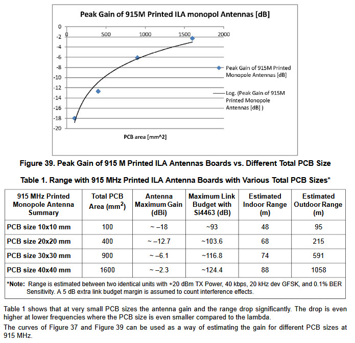
Conclusion: when you use a small board/gnd and assembly, you will get less range. Period :)
People would say, oki then I'm going to use 2.4ghz, as it can better fit small assembly. Yep, as you know 2.4ghz penetration is not great (can be half range after one concrete wall..there are excel sheets for calculating this).
This can be a start for explaining why people can sometimes complain about zwave, zigbee range (with HA people are looking after smaller and smaller device..)
Hello! It looks like you're interested in this conversation, but you don't have an account yet.
Getting fed up of having to scroll through the same posts each visit? When you register for an account, you'll always come back to exactly where you were before, and choose to be notified of new replies (either via email, or push notification). You'll also be able to save bookmarks and upvote posts to show your appreciation to other community members.
With your input, this post could be even better 💗
Register Login