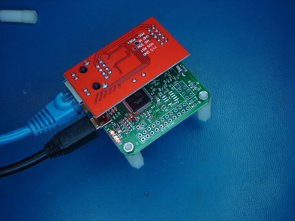
My First MySensors Project
-
Note: This post contains nothing new, all the information presented here is from the MySensors website and / or forum.
This is an account of my foray into the world of MySensors. I started with absolutely no experience with MySensors, however I have built some AVR and Arduino projects in the past. Comments and corrections are very welcome.About me, I am a detail oriented person who feels more comfortable understanding something as opposed to just following directions. This has caused me some consternation with the MySensors as the Arduino platform is designed for those who don’t wish to get into the details (at least not in the beginning).
My goal:
I started a MySensors project to add my own sensors to my VeraPlus. I set my immediate goal on a simple configuration:
- Gateway connected via Ethernet (although a serial gateway would be easier, my VeraPlus has only 1 USB port, it is being used by other hardware and I just didn’t want to add a USB hub)
- One node reporting a counter value.
Starting off:
After reading through much of the MySensors site, I needed to choose the hardware for the Gateway and sensor node.
The first decisions were the radio and the gateway controller board.Radio:
There are only two commonly used radios with the MySensors system, NRF24 and the RFM69W. Reading through the forums and MySensor page comments folks seemed to experience better connectivity with the RFM69 radio. In addition the NRF24 operates at 2.4 Ghz while the RFM69 was at 915Mhz (for the US). I wanted to stay away from our WiFi and cordless phone frequencies. So I decided to go with the RFM69HW-915. The “H” in HW is for the high power version. As the gateway will be powered by an AC adapter (not batteries), it seemed an easy decision to go with the high power version.
Radio Antenna:
Lots of info on the antenna for these radios. For ease in initial testing I choose a simple coil antenna (from ebay). I could further address the antenna once the system was running.
Gateway:
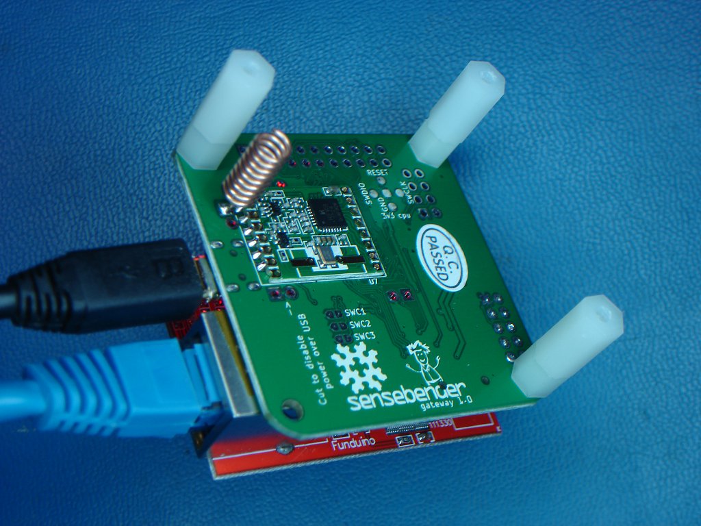
The Ethernet version of the gateway requires more cpu capability than the serial version. Folks said I would need a Mega2560. I started down that road then realized the Mega2560 was a 5V device and the RFM69HW was a 3.3V device and the inputs were not 5V tolerant. I could have used level adapters but the wiring would start to get ugly. Then I started to look and the Arduino Zero which has plenty of capacity. Reading further I found the MySensors system stores the Node ID’s in EE memory which is lacking on the Zero! Hmmm. I then looked at the Sensebender GW. This board is designed for the MySensors system using the same processor as the Arduino Zero and has EE memory….perfect! So that was the direction I went. Besides the Sensebender GW makes a very nice package.
BTW Later I found the MySensors Node ID’s were not written all that often so I could have stayed with the Zero which can store data in its flash memory. But I do not regret going with the Sensebender GW as it makes a real nice package.Ethernet Adapter:
Once the Sensebender GW was chosen, the Ethernet board was easy. We use the W5100 that plugs right into the GW.
Node Hardware:
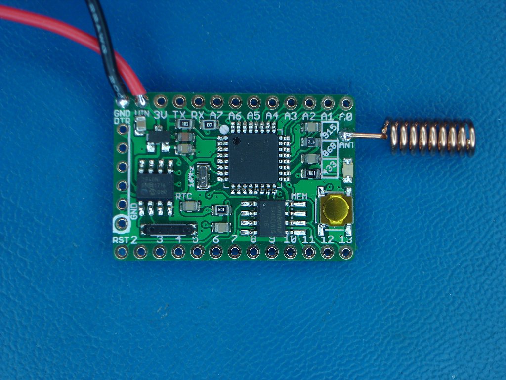
Well we already know the radio will be a RFM69HW-915 (high power) or the RFM69W-915 (standard power). I could have easily used an Arduino Pro Mini (3.3V / 8 Mhz). However I found the Anarduino MiniWireless which would make a very neat package (see a trend here).
I purchased their “-W-915 RFM69W 915Mhz” board. It presents a nice clean assembly and comes with the radio installed. For those who wish to “roll their own” and assemble the radio to a CPU board, I expect it is not a difficult proposition.Assembling the hardware:
Note about my assembly. I’ve been building electronic devices for some time. I’m lucky enough to have a decent ESD mat (you will see the blue background in the photos) and a good soldering iron.
For the node all I had to do was to solder the antenna and wires for power.Now with the remaining hardware on hand the next step was to assemble the gateway (aka GW).
My gateway parts:_
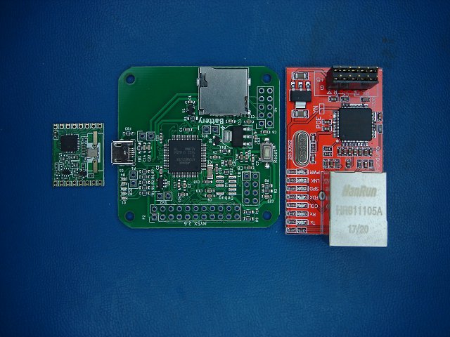
Radio, Sensebender_GW, Ethernet Adapter=== PHOTO === PARTS ===
_Soldering the radio: _
I used 0.020” diameter no-clean 63/37 solder. While this is not “no lead” solder, it is best for hand soldering many parts. The reason is that 63/37 has no solidus phase which means it essentially goes from liquid to solid reducing the possibility of “cold” solder joints. The diameter is not critical, however the small solder diameter makes it much easier to control the solder amount and get nice looking joints. If you are not good at soldering small parts I suggest you get some small diameter solder.
Soldering the radio to the gateway
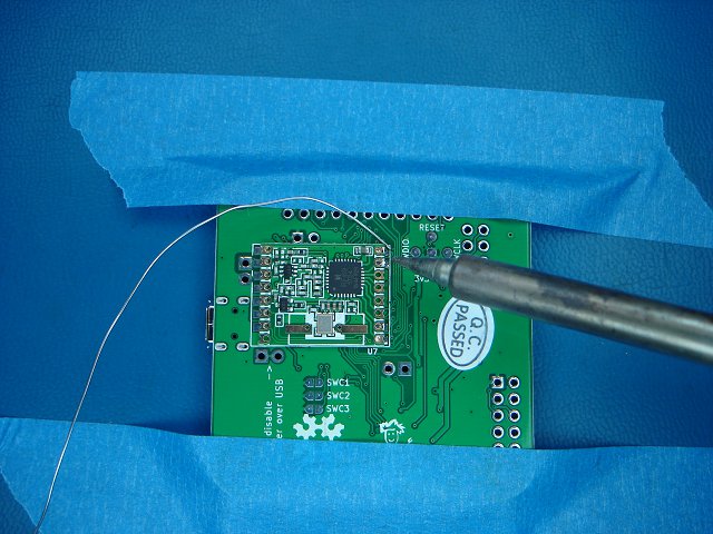
=== PHOTO ==== Soldering radio ===Ethernet Header:
When soldering the Ethernet (W5100) header, the instructions on the MySensors website tells you to raise the header as high as possible. Because the Ethernet jack is taller than the header socket. When doing this be sure you can see the outline of the header pins through the solder. If not you could have a condition where the solder bridges the hole and not reaches the pin. This would result in a poor connection which if it becomes intermittent could be a bear to troubleshoot.
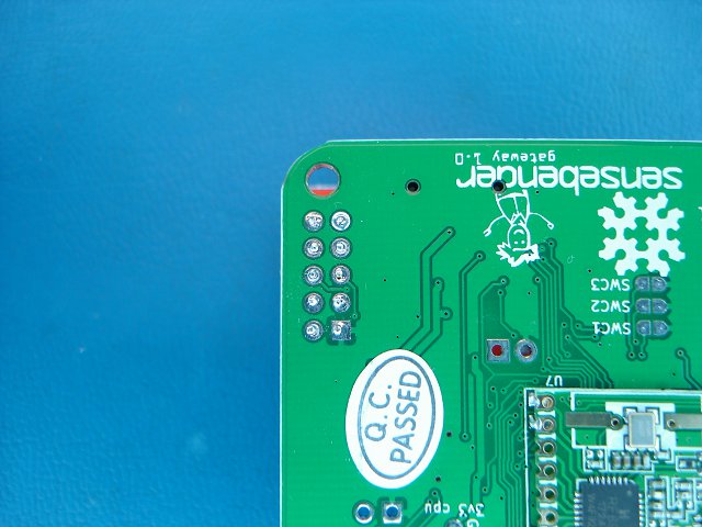
=== PHOTO === Ethernet header ===One issue I found when installing the Ethernet board was a possible interference between a resistor on the gateway board and the metal Ethernet jack housing. I put two layers of Kapton tape on the jack housing to keep them from shorting.
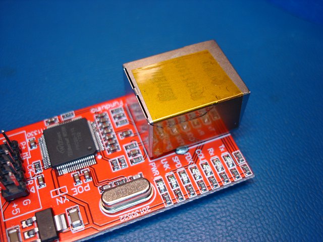
The Final Gateway Assembly:
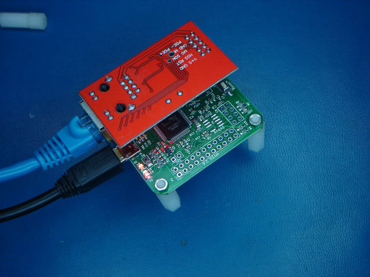
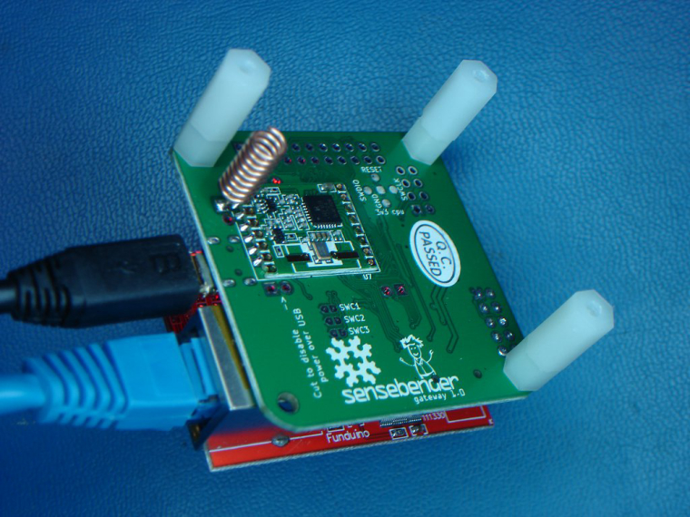
The Final Node Assembly:
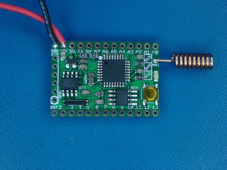
=== PHOTO === Final Assemblies ===
Testing the Gateway
One of the problems with a project like this is the inability to test each piece. When starting off one has no radio to test the radio function. However it was suggest by
tbowmo to try the example "Examples/Ethernet/WebServer" ? to prove that the Ethernet module is up and running.
In addition, zboblamont pointed me to this site to decipher the serial monitor messages is via the log parser, https://www.mysensors.org/build/parserSoftware:
I am using Arduino IDE 1.8.5
I started on the gateway software first. It turns out my detailed approach did not help me. For me the Arduino approach of using the original Arduino Uno board numbers for pin references was too abstract. I’m used to being able to look and the cpu datasheet and finding the info I needed. This was especially so with the Sensebender GW which used a whole bunch of pins that did not exist on the Uno. Have no fear, it all worked out.
See here for the MySensors information and how to install the Sensebender GW board code in the Arduino IDE Sensebender Gateway instructions.Gateway Code:
Attached is my gateway code. I’ve annotated any changes made to the original found at Ethernet gateway. All my changes are preceded by **** you can see them in the listing. As you can see I needed to make only a few “selections” for the hardware I am using.
// GatewayCode_004b  Compiles with Lib V2.2.0 2018-01-31
// was MySensorsGateW5100Code modified V01b   (compiles, this will become our Gateway code!)
// it seems the GatewayCode_003 had problems, likely because we made some erroneous modification.

// In future consider including some Sensebender_GW routines found in the
//  example: %user%\Documents\Arduino\libraries\MySensors\examples\SensebenderGatewaySerial.ino

/**
 * The MySensors Arduino library handles the wireless radio link and protocol
 * between your home built sensors/actuators and HA controller of choice.
 * The sensors forms a self healing radio network with optional repeaters. Each
 * repeater and gateway builds a routing tables in EEPROM which keeps track of the
 * network topology allowing messages to be routed to nodes.
 *
 * Created by Henrik Ekblad <henrik.ekblad@mysensors.org>
 * Copyright (C) 2013-2015 Sensnology AB
 * Full contributor list: https://github.com/mysensors/Arduino/graphs/contributors
 *
 * Documentation: http://www.mysensors.org
 * Support Forum: http://forum.mysensors.org
 *
 * This program is free software; you can redistribute it and/or
 * modify it under the terms of the GNU General Public License
 * version 2 as published by the Free Software Foundation.
 *
 *******************************
 *
 * REVISION HISTORY
 * Version 1.0 - Henrik EKblad, contirbutions by, a-lurker, Anticimex,
 *               Norbert Truchsess <norbert.truchsess@t-online.de>
 *               and Tomas Hozza <thozza@gmail.com>
 *
 *
 * DESCRIPTION
 * The EthernetGateway sends data received from sensors to the ethernet link.
 * The gateway also accepts input on ethernet interface, which is then sent out to the radio network.
 *
 * The GW code is designed for Arduino 328p / 16MHz. Could be why the Anarduino MiniWirelessW pushes the 3.3V 328p to 16Mhz
 *
 * LED purposes:
 * - To use the feature, uncomment MY_DEFAULT_xxx_LED_PIN in the sketch below
 * - RX (green) - blink fast on radio message received. In inclusion mode will blink fast only on presentation received
 * - TX (yellow) - blink fast on radio message transmitted. In inclusion mode will blink slowly
 * - ERR (red) - fast blink on error during transmission error or receive crc error
 *
 * See http://www.mysensors.org/build/ethernet_gateway for wiring instructions.
 *
 */

// Enable debug prints to serial monitor
#define MY_DEBUG

// Enable and select radio type attached
//#define MY_RADIO_NRF24
//#define MY_RADIO_NRF5_ESB
#define MY_RADIO_RFM69						// **** select the RFM69 radio
//#define MY_RADIO_RFM95
#define MY_RFM69_FREQUENCY RFM69_915MHZ     // **** added from forum suggestion
#define MY_IS_RFM69HW						// **** added from forum suggestion
#define MY_DEBUG_VERBOSE_RFM69

// Enable gateway ethernet module type
#define MY_GATEWAY_W5100

// W5100 Ethernet module SPI enable (optional if using a shield/module that manages SPI_EN signal)
#define MY_W5100_SPI_EN 4					// **** enable as the W5100 does not manage the EN signal, the Arduino "ethernet shield" does.

// Enable Soft SPI for NRF radio (note different radio wiring is required)
// The W5100 ethernet module seems to have a hard time co-operate with
// radio on the same spi bus.
#if !defined(MY_W5100_SPI_EN) && !defined(ARDUINO_ARCH_SAMD)
#define MY_SOFTSPI
#define MY_SOFT_SPI_SCK_PIN 14
#define MY_SOFT_SPI_MISO_PIN 16
#define MY_SOFT_SPI_MOSI_PIN 15
#endif

// When W5100 is connected we have to move CE/CSN pins for NRF radio
//									  	**** I was confused here as the comment references the W5100 which we have but the code only "talks" to the RF24 radio
//										**** it turns out this is not an issue so don't worry about it.
#ifndef MY_RF24_CE_PIN
#define MY_RF24_CE_PIN 5
#endif
#ifndef MY_RF24_CS_PIN
#define MY_RF24_CS_PIN 6
#endif

// Enable UDP communication
//#define MY_USE_UDP  // If using UDP you need to set MY_CONTROLLER_IP_ADDRESS below

// Enable MY_IP_ADDRESS here if you want a static ip address (no DHCP)
#define MY_IP_ADDRESS 192,xxx,xxx,xxx			//**** added my desired ip address for the gateway

// If using static ip you can define Gateway and Subnet address as well
#define MY_IP_GATEWAY_ADDRESS 192,xxx,xxx,xxx	//**** added the ip address of my router
#define MY_IP_SUBNET_ADDRESS 255,255,255,0

// Renewal period if using DHCP
//#define MY_IP_RENEWAL_INTERVAL 60000

// The port to keep open on node server mode / or port to contact in client mode
#define MY_PORT 5003

// Controller ip address. Enables client mode (default is "server" mode).
// Also enable this if MY_USE_UDP is used and you want sensor data sent somewhere.
//#define MY_CONTROLLER_IP_ADDRESS 192, 168, 178, 254

// The MAC address can be anything you want but should be unique on your network.
// Newer boards have a MAC address printed on the underside of the PCB, which you can (optionally) use.
// Note that most of the Ardunio examples use  "DEAD BEEF FEED" for the MAC address.
#define MY_MAC_ADDRESS 0xDE, 0xAD, 0xBE, 0xEF, 0xFE, 0xED

// Enable inclusion mode
#define MY_INCLUSION_MODE_FEATURE
// Enable Inclusion mode button on gateway
//#define MY_INCLUSION_BUTTON_FEATURE
// Set inclusion mode duration (in seconds)
#define MY_INCLUSION_MODE_DURATION 60
// Digital pin used for inclusion mode button
//#define MY_INCLUSION_MODE_BUTTON_PIN  3

// Set blinking period
#define MY_DEFAULT_LED_BLINK_PERIOD 300

// Flash leds on rx/tx/err
// Uncomment to override default HW configurations
//#define MY_DEFAULT_ERR_LED_PIN 7  // Error led pin
//#define MY_DEFAULT_RX_LED_PIN  8  // Receive led pin
//#define MY_DEFAULT_TX_LED_PIN  9  // Transmit led pin

#if defined(MY_USE_UDP)
#include <EthernetUdp.h>
#endif
#include <Ethernet.h>
#include <MySensors.h>

void setup()
{
	// Setup locally attached sensors
}

void presentation()
{
	// **** I was originally going to add a sensor to the gateway but did not know how to include it so the idea was abandon.
}

void loop()
{

  wait(2000);					// **** not sure this is required / helps / hurts
}
================= gateway code========================
To download the code to the Sensebender GW in the Arduino IDE I selected:
- Tools / Board: Sensebender Gateway
- Tools / Port: whatever port your computer assigns to the Sensebender board.
- Tools / Programmer: Arduino as ISP (I don’t think this matters)
-
Press the Arduino IDE _upload_ icon. Sorry, I think of programming the board as downloading, Arduino defines it as upload. Both the same function.
At this point I could “see” the IP address in my router under “wired connections”.
I could also “ping” it from the PC command prompt. So I know the controller and W5100 were working fine as I believe the ping return requires the CPU software (but not sure).Node Code:
// Sensor node code -  Use Multimeter but send loop counts for volts
// 2018-02-01  V_01a
// Target: Aarduino MiniWirelessW-915
// MySensors Library V2.2.0
// from:  https://www.mysensors.org/download/sensor_api_20

// IDE Configuration:
//  Board: Duemilanlove
//  Programmer:  AVR ISP

#define MY_DEBUG

// *** Hardware / MySensors Initialization *** //
#define MY_RADIO_RFM69
#define MY_RFM69_FREQUENCY RFM69_915MHZ
#include <MySensors.h>

// *** Node Initialization *** //
#define CHILD_ID 5
#define sensortype S_MULTIMETER

#define analoginputPIN A0
#define LEDPIN 9 //PB1 is pin 9 on ProMini
#define NODE_TXT "Initial_JohnRob_Node"
uint8_t MyCount;

MyMessage msg_Voltage(CHILD_ID, V_VOLTAGE);

void setup()
{
pinMode(LEDPIN, OUTPUT);
  delay(1);                     // was in example where the setup() was empty, likely adds some timing safety margin
}

void presentation()
{
// Send the sketch version information to the gateway and Controller
  sendSketchInfo(NODE_TXT, "01a");
  present(CHILD_ID, S_MULTIMETER);
//  DEBUG_PRINTLN(F("Sensor Presentation Complete"));  // commented out because I don't know how to use this feature.
}

void loop()
{
// Toggle LED
  asm ("sbi %0, %1 \n": : "I" (_SFR_IO_ADDR(PINB)), "I" (PINB1)); // Toggle LED

  // a simple counter to be used for troubleshooting and radio range testing
	if (MyCount < 255){
		send(msg_Voltage.set(MyCount));
		}
	else {
		MyCount = 0;
		send(msg_Voltage.set(MyCount));
		}
    MyCount = MyCount + 5;

  wait(5000);    //unsigned long
}
The node code is very simple. I used the S_Multimeter sensor type to relay a simple count by 5, wrapping to 0 at 250. Because the Anarduino I’m using runs the 328p at 16Mhz, you have to use the Duemilanlove as board type.
I downloaded the node code using a FTDI USB to TTL board (with a real FTDI chip). Programming was simple.=== Node Code ===
Pairing the Gateway to VeraPlus
I have a VeraPlus using UI7. I paired the gateway with the Vera by following the instructions here =============Connect to Vera link=============
The only difference I found was the instructions are for the Vera UI5 but the steps are the same. Also, when I downloaded the Vera Plugin from Github as a zip, the sensors we each in a subdirectory so one simply has to add the required files from each subdirectory or move all to one directory.
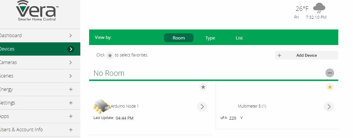
I ended up with a device in Vera that looked like this:
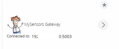
===Vera MySensor device ===In the above device under “settings” I found the below screen:
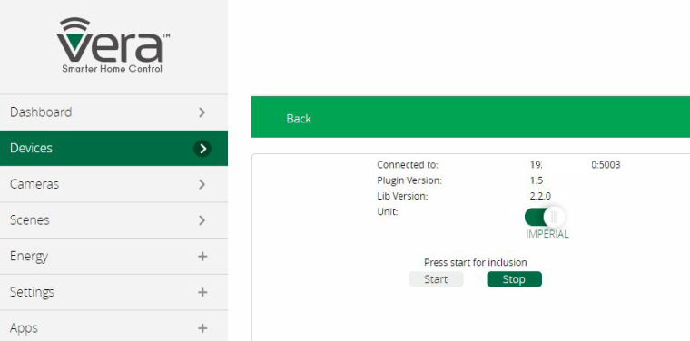
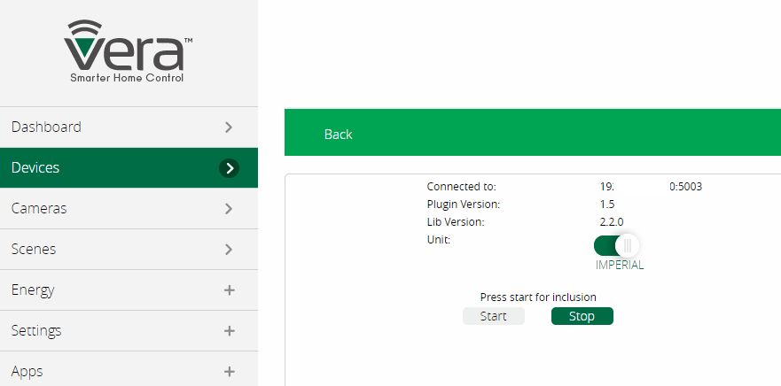
=== Vera Include Screen ===How I included my node:
- Turn off power to the node.
- Press the “Start” button in Vera (see above)
- You will see 0 devices found
- Power on the Node
- In a few moments you will see 2 devices found.
- I waited for the inclusion to time out
Vera then showed two new devices: (see below)
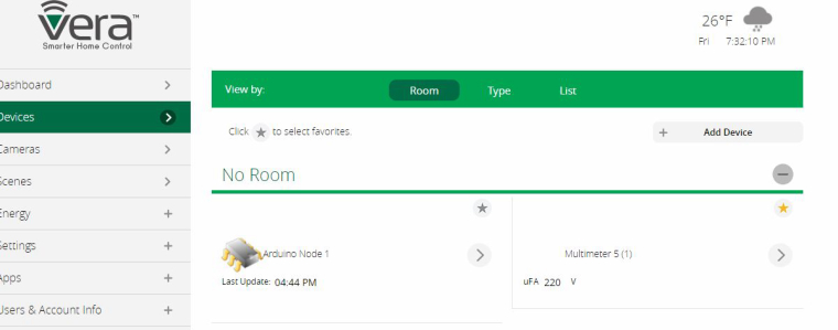
=== Vera device screenshots ===
The Multimeter is only setup to report Volts (see node code). The displayed value incremented in steps of 5 as programmed by the node code.
All worked well!! Amazing.
Range testing:
Clearly not a scientific test but I’ll describe my longest range tested.
I live in a 1 family house, the houses are about 30 to 50’ apart. My gateway was in my basement; I carried the sensor node to the opposite side of my neighbor’s home and was getting a usable signal. So I decided to keep the spring type antenna for both the Gateway and Node._Conclusion: _
The MySensors concept can be a little intimidating at first, especially given the breath of hardware one could choose from. But HEK and contributors did an amazing job of creating and executing the concept.
As I said in the beginning, I offer no original content, just recounting my reasoning and steps in the hope that it will speed the initial steps of those who follow and maybe help some continue when they would otherwise abandon the MySensors concept._Next Steps: _
I have a housing on order for the gateway. I'm still thinking about how to mount the boards so the connections are available.
For the nodes, I plan on investigating how low I can get the current of Anarduino MiniWireless before planning any battery operated nodes.

