so, nobody can help me with this issue ?
A
ady_e_n
@ady_e_n
Posts
-
Modifying a Raspberry Pi dislay -
Modifying a Raspberry Pi dislayHi All,
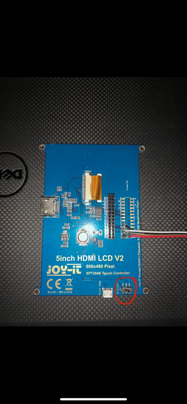
I got this 5" raspberry pi display, XPT2046 Touch Controller. Currently it has a hardware backlight on/off switch and i'm looking to change that to be able to turn on and off the backlight using a script from raspberry pi.
I am looking for an always on gate that i can control through a pin. My initial thought was to place a tranzistor, but not sure if that will work. Any other ideas ? how can i achieve this really simple and easy ?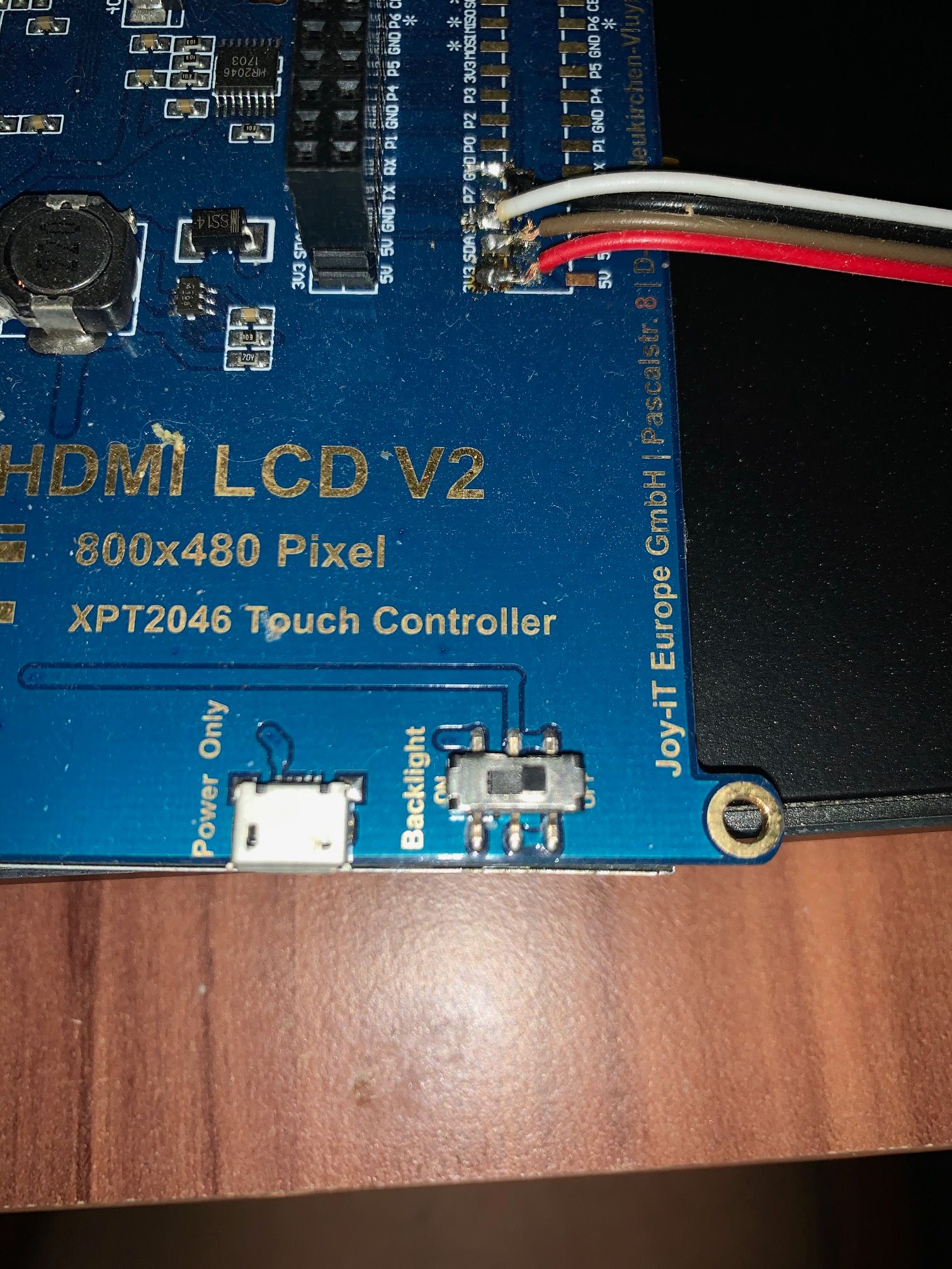
Regards
Adrian. -
livolo Glass Panel Touch Light Wall Switch + arduino 433MhzHi All,
I'm trying a different approach, on how to use just the top (sensor) part of the livolo touch switch, but at the moment, i'm stuck at the PIC16f690 microcontroller functions in order to power up the LED.
I'm using a Livolo VL-C601-2 model and based on the wires on the top part, i tried to make a diagram to batter understand the schematics. (Please note that i'm missing some wires and that i have not drawn all the wires from all the pins as i could not see all of them. If something is wrong, please let me know.)
What i don't understand from the diagram below, is how does the PIC16F690 controls the two LEDs (red and blue) using only the RB4 (13) pin.
From the datasheet link here i can see that the Pin 13 (RB4) has: RB4/AN10/SDI/SDA and supports IOC
Can someone please explain to a noob in electronics how does this work and how does the pic switches from one LED to the other ?
