Skip to content
  • MySensors
  • OpenHardware.io
  • Categories
  • Recent
  • Tags
  • Popular
Skins
  • Light
  • Brite
  • Cerulean
  • Cosmo
  • Flatly
  • Journal
  • Litera
  • Lumen
  • Lux
  • Materia
  • Minty
  • Morph
  • Pulse
  • Sandstone
  • Simplex
  • Sketchy
  • Spacelab
  • United
  • Yeti
  • Zephyr
  • Dark
  • Cyborg
  • Darkly
  • Quartz
  • Slate
  • Solar
  • Superhero
  • Vapor

  • Default (No Skin)
  • No Skin
Collapse
Brand Logo
A

aproxx

@aproxx
Hero Member
About
Posts
44
Topics
1
Shares
0
Groups
2
Followers
3
Following
0

Posts

Recent Best Controversial

  • 💬 AC-DC double solid state relay module
    A aproxx

    @Soloam I'm actually not using 2 100nF capacitors, but 1 100nF and 100 uF capacitor. Exactly for the reason that scalz mentioned. :) I'm not saying these are the perfect values to use, but I came across similar values some time ago, and these give me a decent and stable voltage.

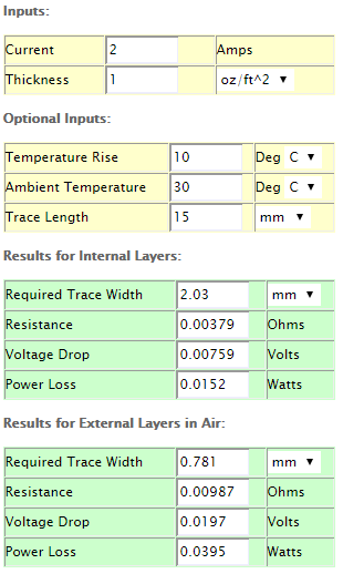
    The width of my copper traces is 2mm for the entire high voltage circuit. I have used a trade width/thickness calculator, and it should be more than sufficient to power the HLK-PM01.
    However, it is not sufficient for the traces between the relays and the connectors because it should be able to handle up to 2A (limiting factor of the solid state relays). That's why I have designed this board with open air traces between the relays and the connectors. That way it's possible to reinforce the traces with solder, after which it should be able to withstand 2 Amps.

    And good luck with designing your version of the board! If there is a way to decrease the board size even further that would be great!

    OpenHardware.io hlk-pm01 solid state relay light switch light acdc

  • 110v-230v AC to Mysensors PCB board
    A aproxx

    @jemish
    It's on the middle of the board on the top side. 4 pins are present to use as switch inputs. 2 pins are ground, and then pin 4 and 7 are available as well.
    By closing the connection between pin 4 and ground you will switch te status of relay 1. When closing the connection between ground and pin 7 you'll switch the status of relay 2.

    Hardware

  • 💬 AC-DC double solid state relay module
    A aproxx

    @Samuel235
    I assume you were referring to the 2 resistors at the high voltage circuit? These were actually used as placeholders for the temp cutoff and the slow blow fuse. As I didn't have these component in DipTrace I used resistors to replace them in the scheme. But I have updated the schematic to avoid any confusion!

    As for the EAGLE software: Is does meet all the needed requirements, but I just find DipTrace to be way more user-friendly.

    OpenHardware.io hlk-pm01 solid state relay light switch light acdc

  • 💬 AC-DC double solid state relay module
    A aproxx

    @Samuel235 At the moment I have one board (version 3.3.1, which is missing the temperature sensor) up and running for over a week. It's in a small closed box, and it has two lamps attached to it which are powered on every evening. So far everything seems to be ok. Temperature is still low inside this box after a few hours (couldn't perform any specific measurements yet, so that's why I added the temperature sensor in this one).

    @Cliff-Karlsson I just soldered the thermal fuse really quick. But maybe some other kind of heatsink would be useful! So any suggestions are welcome for this. :)

    @Samuel235 I have been using DipTrace to design all my PCBs, and I must admit that the schematic view in this software kit isn't the best.. I'll see what I can do to have the schematic quality improved! But all components which are on the schematic are on the PCB, so no components are missing on the board itself.

    OpenHardware.io hlk-pm01 solid state relay light switch light acdc

  • 110v-230v AC to Mysensors PCB board
    A aproxx

    The latest version of this board is available here!
    Because of the large number of request a second (optional) solid state relay has been added to the board. Enjoy!

    Hardware

  • 110v-230v AC to Mysensors PCB board
    A aproxx

    @Sefi-Ninio
    Yes, it will be perfectly possible to just install 1 relay on the board and it will still work fine.
    More news in the next few days! ;)

    Hardware

  • 110v-230v AC to Mysensors PCB board
    A aproxx

    @jemish
    Then your wait is almost over! :) I'm currently doing my latest tests on the board, and so far everything works perfectly. I'll try and see if I can post everything during next weekend.

    Hardware

  • 💬 Bed Occupancy Sensor
    A aproxx

    Have you ever considered adding a weight/pressure sensor underneath the legs of your bed?
    Lets say if the weight of your bed would be 100kg, that the arduino is configured set to toggle at 110kg? :)

    OpenHardware.io mpr121 capacitive occupancy bed touch

  • 110v-230v AC to Mysensors PCB board
    A aproxx

    Hi @shabba.
    I assume you mean version 3.2.3 of the board?
    Besides the silkscreen of the LE33 being the other way around, there are a few other things to keep in mind:

    • The drill holes of the fuse/varistor on the 230v side might be a bit small. So it is advised to either make those holes a bit bigger, or to make the legs of the fuse/varistor a bit thinner using some sandpaper.
    • Make sure to solder the components in the correct order (As mentioned in the Word document, which is part of the ZIP file of the opening post).

    I'll update the first post of this topic in a few weeks, which includes the newer board version that fixes all the problems as stated above.

    Hardware

  • 110v-230v AC to Mysensors PCB board
    A aproxx

    @jemish The boards were sent to me from China 5 days ago. I don't have a tracking number available, but usually it takes between 3 and 5 weeks before they reach me (Belgium). I already have all the necessary components, so within a week after I received the boards I'll provide this topic with an update.

    Hardware

  • 💬 jModule
    A aproxx

    Any chance you will be creating a 'panelized' version of this board? With these small sizes 4 boards can be fitted on a 5 by 5cm board, while still keeping the same price. I'd be happy to order a few if that's available!

    OpenHardware.io mysensors contest2016

  • 110v-230v AC to Mysensors PCB board
    A aproxx

    @vil1driver said:

    bad news :-/ then why have you fuse at home ? 400 000 V has security measures, why add more security ? it's juste our life, childs life !!
    do you know what is a "security transformer" ? the hlk-pm01 isn't one.

    It's not that I think that security isn't important, but I believe that no security on the low voltage side is safer than having a false sense of security. As I've read above, lots of the low voltage fuses were not reliable. And that's one reason I dropped it in the newer design.

    All that aside: I never ever EVER intend to mount these boards on locations people can reach (unless they intend to). Everything is placed safely behind a light switch or in a completely closed plastic box. The only thing that COULD be touched is the wires to the switch itself (And even those will be out of reach if the lid of the switch is on). But since these switches are only connected to ground and a digital input, those wires don't do any harm.

    But yes, I do know what a 'security transformer' is. And no, I completely agree the HLK-PM01 itself isn't a secure transformer. But considering the price, the added fuses and temp cutoffs, and the plan to mount these in a safe location, I believe the HLK-PM01 does the job well. ;)

    Hardware

  • 110v-230v AC to Mysensors PCB board
    A aproxx

    @hek That sounds as a great idea. I'll share it on OpenHardware as soon as I have confirmed that everything works as expected!

    Hardware

  • 110v-230v AC to Mysensors PCB board
    A aproxx

    Wow, this thread has been really active in the past few months! I'm sorry for my absence, but I kind of got dragged into other projects.. :)

    A new version of the board will be shared soon! Compared to the current board following changes have been made:

    • A second solid state relay has been added. This 2nd relay is optional, so if only 1 device needs to be controlled just 1 relay needs to be installed and everything will still work fine.
    • The board size has been increased just a little bit to fit this 2nd relay. Size is still 5x5cm only.
    • Some components have been moved in order to make it easier to solder them (This was a bit tricky on version 3.2.3 because some components were really close to each other).
    • Traces between the relays and the connectors are now 'open air'. So there is no mask on top of the traces. This way it is possible to reinforce the traces. By doing this it shouldn't be any problem to connect a 2A load to the board.
    • A temperature cut-off has been added to the board.
    • The varistor for the low voltage circuit has been removed because it's not really needed anymore with all the extra security measures on the high voltage side of the board.

    Currently this board is still on it's way from China, but as soon as I've received this board I'll share all the documentation and everything else which is needed on this forum! This will probably happen in 3-5 weeks from now, so stay tuned! ;)

    Hardware

  • 110v-230v AC to Mysensors PCB board
    A aproxx

    @mvdarend Thanks for the feedback! Happy to hear that it's working fine on your side as well. Although I do find it strange that the LE33 seems to be the other way around on your board? Maybe I just made a mistake with the silkscreen, and should the LE33 be on the bottom side? Anyway, I'll make sure to address this as soon as I possible (probably somewhere during next week). Sorry for the possible inconvenience, but thanks for pointing this out! :)

    @sundberg84 The board dimension are about 4.2x4.7cm, so it is quite small. However, I'm afraid that because of the NRF24L01 module, and the 230v connections to it, it wouldn't really fit the box you have on that picture (assuming the board you have there is 5x5cm)..

    Somewhere in the next week or 2 I'll try to design a custom 3d printable plastic box for the board that I've designed. Together with a 2-relay board as requested by @jemish .

    Hardware

  • 110v-230v AC to Mysensors PCB board
    A aproxx

    @mvdarend I'm not sure if I completely understand what you mean by "pulse switch"..
    I was planning on using a normal light switch, in order to have an on/off (open and closed) circuit.
    But it shouldn't be a problem to modify the code a bit in case you're using some other buttons (like a push button for example). I'm sure me or somebody else on this forum can help you with your code in case it shouldn't work out as expected. :)

    Hardware

  • Soldering iron / station requirements
    A aproxx

    Depending on the country you would like to ship the soldering station, this one might be a good option as well:
    LINK
    But the shipping cost is highly dependent on the selected country, so it is better to check the shipping cost first.
    It is a decent copy of the well known Hakko 936 soldering station.
    I bought it about 6 months ago, and I'm absolutely happy with this one. And because it's a copy of a well known soldering station there are a bunch of different solder tips for this one available on AliExpress.

    General Discussion

  • My Slim 2AA Battery Node
    A aproxx

    Thanks for the detailed information about this project! I was/am looking for a similar solution to check whether doors are opened or closed.
    Have you ever considered drilling a hole in the top of the door, and placing the entire node inside this drilled hole like the video below? Similar to this video?
    That was something I planned to do, but your solution seems really nice as well in case drilling a hole in the door doesn't work out as expected.

    My Project

  • 110v-230v AC to Mysensors PCB board
    A aproxx

    @Jan-Gatzke Indeed, most of my lights only consume like 10% of the maximum rated power, so I should be on the safe side for sure.

    I have attached a ZIP file which contains all required information in one of my previous posts (HERE). That one contains a Word document with all components and an AliExpress/Ebay link.

    I'll try and see if I can update the first post of this topic as well to include all important information.

    Hardware

  • 110v-230v AC to Mysensors PCB board
    A aproxx

    @Jan-Gatzke I've used a similar calculator before and according to these calculation it isn't mandatory.

    • Dirtypcbs.com claims to use 1oz/ft2 copper thickness (which seems to be 0.035mm).
    • The traces between the solid state relay and connectors are all 2mm wide.
    • Distance between the solid state relay and the connector on the edge is less than 20mm.

    That would lead to the following calculations:
    Schermafdruk 2015-09-22 13.35.55.png

    So you are right that it isn't mandatory to reinforce these traces. However, to be on the safe side I'm still planning to reinforce them. I know, it probably isn't necessary but it doesn't hurt putting this extra effort in, just to be completely safe. :)

    Hardware
  • Login

  • Don't have an account? Register

  • Login or register to search.
  • First post
    Last post
0
  • MySensors
  • OpenHardware.io
  • Categories
  • Recent
  • Tags
  • Popular