Navigation

    • Register
    • Login
    • OpenHardware.io
    • Categories
    • Recent
    • Tags
    • Popular
    1. Home
    2. chrille
    3. Best
    • Profile
    • Following
    • Followers
    • Topics
    • Posts
    • Best
    • Groups

    Best posts made by chrille

    • RE: ESP8266 RFM69 gateway

      As promised a short description of my ESP8266/RFM69 gateway.

      I made several attempts on building a gateway on breadboards/veroboards, but they didn't work well (NRF24 worked fine). The RF part was very sensible. I either had to touch the antenna with a finger to get things working, or move the antenna away from the board. Eventually I decided to try to make a real PCB. It was also a good excuse to get back into making my own PCB's as the last one I made was made with OrCAD under MSDOS, more than 20 years ago!

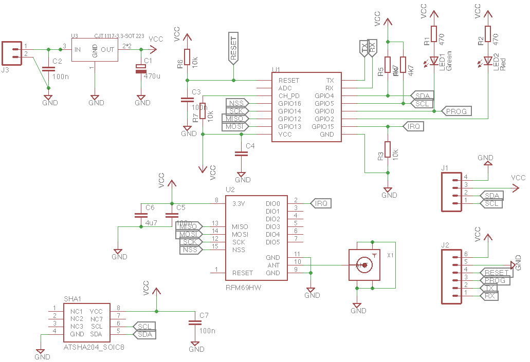
      This is the schematic:

      0_1474307652006_mysensors-esp8266-rfm69.png

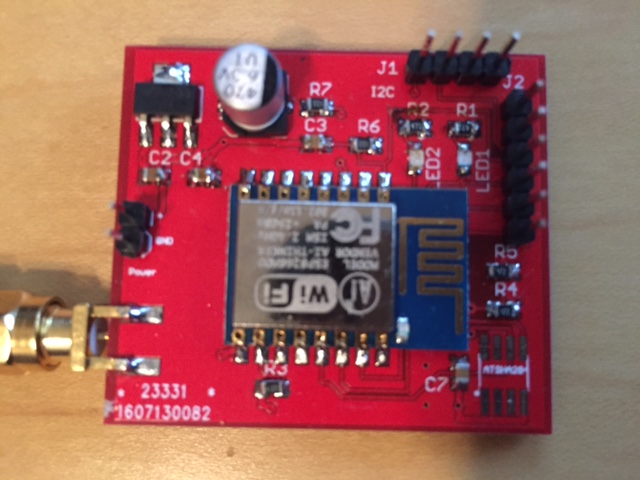
      And the finished PCB - top layer:

      0_1474307730463_IMG_2991.JPG

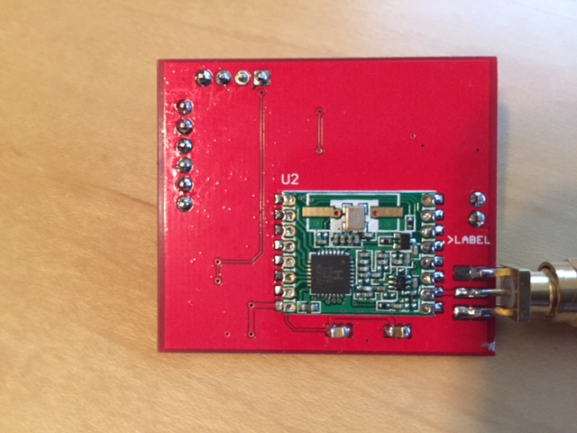
      ...and the bottom layer with the RFM69

      0_1474307749939_IMG_2992.JPG

      A few comments:
      All passives are 0805 which are pretty easy to solder.
      The library I used for ESP8266 have GPIO4 and 5 swapped, which means SDA and SCL are swapped on J1. Not a big issue for a gateway, but I decided to include I2C support for display or local sensors
      I added the ATSHA204, because there was room on the board - I think I screwed up on this, since this is the 8-pin version and everyone else uses the 3-pin version with the proprietary Atmel interface.
      PCB's was ordered from Dirty PCB's and showed up in approx 3 weeks - it's a 1.6 mm PCB - next time I should order 1.2 mm PCB's to avoid having to bend the legs on the SMA connector

      On the positive side - it works. No issues with touching the antenna and the ESP8266 doesn't crash. I2C is also tested with a different (non-MySensors) sketch. ATSHA support is untested and probably doesn't work.

      The reason for using GPIO16 as chip-select, is because chip select doesn't need a hardware interrupt and it frees up GPIO4+5 for I2C

      The radio related part of the sketch:

      #define MY_RADIO_RFM69
      #define MY_RFM69_FREQUENCY   RF69_868MHZ
      #define MY_RF69_IRQ_PIN 15
      #define MY_RF69_SPI_CS 16
      #define MY_IS_RFM69HW true
      // #define MY_RFM69_ENABLE_ENCRYPTION true
      
      posted in Development
      chrille
      chrille
    • RE: rfm69 frequency question

      @alexsh1 You need to have all modules running at the same frequency, but if you're willing to loose some coverage (and potentially harm the PA of the module) you can tune any version of the module to any frequency supported by the chipset (which is a significant part of the spectrum from 290 MHz to 1 GHz)

      posted in Hardware
      chrille
      chrille
    • New internal message types

      Since it's now possible to have sensors on the gateway and there seems to be a slight shift towards using more advanced hardware (Raspberry Pi, ESP8266, ARM based) I think it would be great to have some additional internal message types to report various internal data from both gateway and sensor nodes. So far I considered the following types

      I_WIFI_RSSI - signal strenght from wifi network (dBm)
      I_RADIO_RSSI - signal strengh from radio (dBm)
      I_MEMORY - free memory (bytes)
      I_UPTIME - uptime (seconds)
      I_CPULOAD - CPU load (%)
      I_VCC - supply voltage (volt)

      • Jan
      posted in Feature Requests
      chrille
      chrille
    • RE: Step by step instructions of how to troubleshoot RFM69 gateway/sensor ?

      I find the Node and Gateway sketches, that comes with the RFM69 library, are very useful to validate the hardware setup.
      They are available from https://github.com/LowPowerLab/RFM69/tree/master/Examples

      It's also my experience that powering the RFM69 modules from an USB adaptor (either 3.3V directly, or 5V to a regulator), doesn't work reliable. I needed to power my RFM69 modules (even the non-H version) from a more reliable power source to get the hardware to work reliable

      posted in Troubleshooting
      chrille
      chrille
    • RE: 💬 FOTA (Wireless Programming)

      Same question as @b0rmann - is it possible to do OTA from a non-Windows environment (Mac OSX or Linux)? A simple implementation in python or perl, that could talk to the gateway, and do OTA from the command line, would be a really nice to have. I would prefer the dualoptiboot solution, since it'll work with RFM69 nodes as well (at least that's my understanding)

      posted in Announcements
      chrille
      chrille
    • RE: PowerSaving cutting

      @Martin-Tellblom said:

      My boards that I have doesn't look like the once in the guide and I don't really know where to cut to disable the power regulator
      The red cut is the LED but should I cut at the green or the yellow?
      The yellow is connected to Vcc 3.3V pin and the green cut is Vcc from the FTDI.
      I think I should cutthe green one but I'm not sure

      And the second thing If I use the sleep(very long number) is the Pro Mini going down in real sleep mode or do I have to do something else?

      The Pro Mini's I have seen have two LED's - one is connected to VCC and the other to one of the GPIO pins. The one that lights up, as soon as the board is turned on, is the one to cut! You can leave the other one in place. As for cutting the regulator, I really don't see the purpose of doing that.
      I have a chinese Pro Mini clone, where I cut the power LED, and nothing else. It's powered by 2x cheap AA batteries and reports every 30 seconds. Every report consists of a battery voltage, temperature and a combinered temperature/humidity measurement. It's been running 4 months and two days, and so far the battery voltage have dropped to 2.97V

      If you use the sleep() function in a MySensors sketch it will put both the processor and the radio to sleep.

      posted in Hardware
      chrille
      chrille
    • RE: [SOLVED] ESP8266 gateway with RFM69 - WDT issues

      After adding another yield() to RFM69.cpp everything works. I have created a pull request to have this added to the code
      https://github.com/mysensors/Arduino/pull/396

      posted in Troubleshooting
      chrille
      chrille
    • RE: How to measure small vibration

      @jesper said:

      How to measure small vibration?
      I must measure when a vaskemasine stops , there are some who know what sensor i should use ?

      In another thread this module was suggested - I have no personal experience with it

      https://www.aliexpress.com/item/1pc-lot-SW-420-Normally-Closed-Alarm-Vibration-Sensor-Module-Vibration-Switch-30512/32259757483.html

      • Jan
      posted in Hardware
      chrille
      chrille
    • RE: [SOLVED] ESP8266 gateway with RFM69 - WDT issues

      @thebillplease said:

      @chrille - would you mind posting a diagram of your wiring? I'm looking at doing the same, but haven't been able to get it to work. Thank you in advance!

      RFM69 <-> ESP8266:

      DIO0 <-> GPIO4
      SCK <-> GPIO14
      MOSI <-> GPIO13
      MISO <-> GPIO12
      CS <-> GPIO15 (AKA NSS)

      And of course GND + VCC

      Another forum user asked for the actual sketches I used for testing - I put them on github: https://github.com/janchrillesen/arduino-stuff
      The gateway sketch also has the wiring in the comments section in the top

      posted in Troubleshooting
      chrille
      chrille
    • RE: Cheap but effective cable connectors to upgrade my projects

      @LastSamurai said:

      Thanks but thats a little expensive for me. Can anyone suggest a good and cheap crimping set for dupont cables?

      I own both the crimping tools shown in this video https://www.youtube.com/watch?v=3Cw9YFLDZeo and I agree with Andreas that the Engineer PA-09 is far superior to the chinese crimper when it comes to crimping dupont connectors. It also works will with JST connectors

      • Jan
      posted in Hardware
      chrille
      chrille
    • RE: [SOLVED] ESP8266 - RFM69W - Are they talking??

      @Dinnoc said:

      I have

      MISO --> 12
      MOSI --> 13
      SCK --> 14

      That's correct

      NSS (assume this is IRQ) --> 15 (which is also pulled down to earth with a resistor)

      No, NSS is chip select (MY_RF69_SPI_CS)
      IRQ needs to go to DIO0 (MY_RF69_IRQ_PIN)

      (No need to configure MY_RF69_IRQ_NUM on ESP8266 was pin and IRQ number always is the same on ESP8266)

      So you need 5 connections (MISO, MOSI, SCK, NSS and IRQ) to the ESP8266 + VCC/GND

      And finally i dont have an antenna. my devices are about 0.5m away from each other. Do i need an antenna? If so does it need to be a speicific length? and what socket of the RF69 do it attach it to (ANA??)

      A quarterwave at 868 MHz is approx 9 cm, so go with a piece of wire at that length, connected to ANA
      It would probably work without an antenna, but to product the PA of the module you should connect just a simple antennna

      Looking at your picture it looks very much like a HW module, and not a H module, so I suggest you configure isRFM69HW

      • Jan
      posted in Troubleshooting
      chrille
      chrille
    • RE: ESP8266 and TTL-UART GPS

      @Martin-Tellblom The values are not critical, as long as the ratio is correct. 1k + 2k2 would work fine

      Connect the two resistors in series and the 5V signal to the 1k resistor and the other end of the resistors to gnd. The 3.3v signal is available between the two resistors

      posted in Hardware
      chrille
      chrille
    • RE: Several ESP8266 Gateways in parallel supported?

      @ragflyer said:

      I am experiencing many ghost sensors and new sensor variables like wind sensors etc. which I have not connected nor built at all.
      It happened after connecting a second Wireless Gateway to reach some sensors in the garden.
      Is this actually supported or should I find another way to increase range?

      It may depend on your controller, but it's possible. I have two ESP8266 gateways connecting to domoticz. One is using NRF24 and the other RFM69. If you want to build two NRF24 gateway I think you need to change the frequency/channel of the second gateway, and the attached sensors

      • Jan
      posted in Troubleshooting
      chrille
      chrille
    • RE: DS18B20 ans SHT31-D show up as combined sensors on Domoticz

      @palande.vaibhav said:

      At the end of discssion gizmocuz says that "this is already taken care of, see the forum thread about mysensors/grouping". But I checked Domoticz forum and couldn't find a thread named grouping in mysensors subforum.

      It does seem to work without any changes to the domoticz code. The following is from a node with DS18B20, Si7021 and TSL2561

      1_1476904421404_Skærmbillede 2016-10-19 kl. 21.09.45.png 0_1476904421404_Skærmbillede 2016-10-19 kl. 21.08.24.png

      Child 1+2 is the Si7021 and child 4 is the DS18B20. The enumeration goes from 1 to 2 as soon as a second V_TEMP is presented

      To push it even further - here's a node with a Si7021 + 10x DS18B20

      (MySensors 2.0.1 beta and Domoticz dev from yesterday)

      0_1476904653813_Skærmbillede 2016-10-19 kl. 21.17.07.png

      This node also works fine with Domoticz and only shows the humidity for the first occurance of V_TEMP (which is the Si7021)

      posted in Troubleshooting
      chrille
      chrille