Navigation

    • Register
    • Login
    • OpenHardware.io
    • Categories
    • Recent
    • Tags
    • Popular
    1. Home
    2. chrille
    3. Posts
    • Profile
    • Following
    • Followers
    • Topics
    • Posts
    • Best
    • Groups

    Posts made by chrille

    • RE: ESP8266 and TTL-UART GPS

      @Martin-Tellblom The values are not critical, as long as the ratio is correct. 1k + 2k2 would work fine

      Connect the two resistors in series and the 5V signal to the 1k resistor and the other end of the resistors to gnd. The 3.3v signal is available between the two resistors

      posted in Hardware
      chrille
      chrille
    • RE: ESP8266 and TTL-UART GPS

      @Martin-Tellblom said:

      Can I connect a TTL-UART (TTL-serial) gps module to a ESP8266?

      I have three of these on my desk and like to use them for something fun with a ESP8266 (Like a small battery powered gps tracker for the kids/dog or so)

      There's conflicting information on whether the GPIO pins on ESP8266 will tolerate 5V. To make sure you don't harm the RX port on ESP8266 I suggest you use a level converter. A simple voltage divider with two resistors should work fine (I use it to connect an Arduino Mega to the serial port of an ESP8266)

      posted in Hardware
      chrille
      chrille
    • RE: [solved] RFM69 based nodes unable to report Lib Version

      @scalz said:

      • List of changes, some notes, and current status : https://docs.google.com/spreadsheets/d/191NpTBogLPijYxS2V_oHZnVlcW4B65J1kXAqYrr4qeE/edit#gid=884074439
      • https://github.com/scalz/Mysensors

      Be a little bit more patient, PR should go soon now as you can see from the current status 😉

      It's great to see work being put into the RFM69 driver. I have tried to install your code and updated my gateway and a sensor node

      On the sensor node I added

      sendSignalStrength(1);
      sendRadioTxLevel(1);
      

      and in the debug window I see

      6899 TSF:MSG:SEND,1-1-0-0,s=255,c=3,t=29,pt=1,l=1,sg=0,ft=0,st=OK:51
      7035 !TSF:MSG:SEND,1-1-0-0,s=255,c=3,t=30,pt=1,l=1,sg=0,ft=0,st=NACK:0
      

      Message type 30 always fails (st=NACK) - is this expected?

      Gateway is ESP8266 and node is Anarduino (328p+RFM69CW)

      posted in Bug Reports
      chrille
      chrille
    • RE: DS18B20 ans SHT31-D show up as combined sensors on Domoticz

      @palande.vaibhav said:

      0_1476918895078_chrome_2016-10-19_16-13-51.png

      I have DS18B20 which is child 5, SHT31-D temperature is child 6 and Humidity is 7.
      Here child 4, 5, 6 have the same number #4 but they are not grouped, they show up as separate sensors in Devices tab.

      I think there's two issue

      1. Something is wrong with the presentation of child 5 (DS18B20) - it should have value V_TEMP - it's empty
      2. You need to change the SHT31 code to present temperature before humidiy - else the humidity of the SHT31 would be grouped with the temp from the DS18B20
      posted in Troubleshooting
      chrille
      chrille
    • RE: 💬 FOTA (Wireless Programming)

      Same question as @b0rmann - is it possible to do OTA from a non-Windows environment (Mac OSX or Linux)? A simple implementation in python or perl, that could talk to the gateway, and do OTA from the command line, would be a really nice to have. I would prefer the dualoptiboot solution, since it'll work with RFM69 nodes as well (at least that's my understanding)

      posted in Announcements
      chrille
      chrille
    • RE: DS18B20 ans SHT31-D show up as combined sensors on Domoticz

      @palande.vaibhav said:

      At the end of discssion gizmocuz says that "this is already taken care of, see the forum thread about mysensors/grouping". But I checked Domoticz forum and couldn't find a thread named grouping in mysensors subforum.

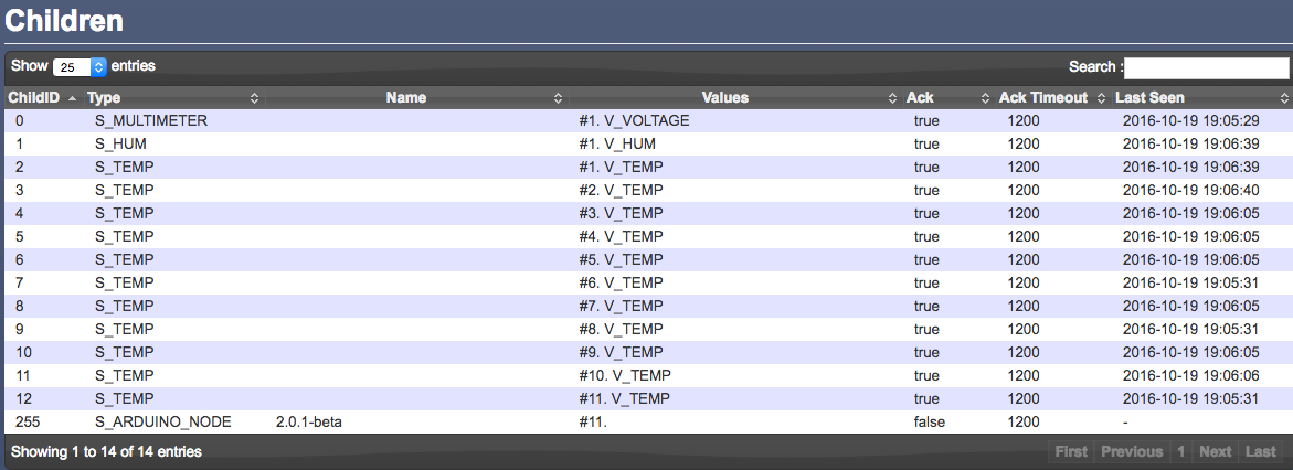
      It does seem to work without any changes to the domoticz code. The following is from a node with DS18B20, Si7021 and TSL2561

      1_1476904421404_Skærmbillede 2016-10-19 kl. 21.09.45.png 0_1476904421404_Skærmbillede 2016-10-19 kl. 21.08.24.png

      Child 1+2 is the Si7021 and child 4 is the DS18B20. The enumeration goes from 1 to 2 as soon as a second V_TEMP is presented

      To push it even further - here's a node with a Si7021 + 10x DS18B20

      (MySensors 2.0.1 beta and Domoticz dev from yesterday)

      0_1476904653813_Skærmbillede 2016-10-19 kl. 21.17.07.png

      This node also works fine with Domoticz and only shows the humidity for the first occurance of V_TEMP (which is the Si7021)

      posted in Troubleshooting
      chrille
      chrille
    • RE: DS18B20 ans SHT31-D show up as combined sensors on Domoticz

      @palande.vaibhav said:

      I am going to try what @AWI has suggested. Presenting sensors in sequence and then spacing them apart when presenting to see what this new feature in Domoticz does.
      Can you also try this? and report here? That would be really helpful.

      Yes, I'll test as soon as time permits and report back

      posted in Troubleshooting
      chrille
      chrille
    • RE: DS18B20 ans SHT31-D show up as combined sensors on Domoticz

      @palande.vaibhav I agree this is very annoying. I have several nodes with a Si7021 and a DS18B20, where the DS18B20 is located some distance from the node (for instance in a freezer or outdoor). This means that the humidity measured by the Si7021 might be vastly different from the humidity where the DS18B20 is located
      I wonder if it would make sense to implement a NODEID_ALIAS (or NODEID_VIRTUAL) in MySensors, so a node could actually present itself as two (or more node ID's), so some sensors/children would belong to the main NODEID and other sensors could belong to another (virtual) NODEID - for the home automation system it would look like two different nodes

      • Jan
      posted in Troubleshooting
      chrille
      chrille
    • RE: Soldering tips for atmega328p-au?

      @NeverDie said:

      Have you tried hand soldering a BME280? It looks a bit more challenging to me than the si7021, but perhaps it's still do-able.

      I only tried the Si7021, where the pads is both on the bottom and a bit on the side. For DFN/QFN's where the pads is only on the bottom I agree it's harder. I saw a interesting concept where the layout had a lot of vias directly under the DFN/QFN and you could heat the PCB from the opposite site using a traditional soldering iron. Of course you would still need solder paste for this

      posted in Hardware
      chrille
      chrille
    • RE: Soldering tips for atmega328p-au?

      @NeverDie I have no experience with reflow ovens but to me it seems that it's mostly useful for batches of boards, since you need to create a stencil for the solderpaste. For a couple of boards handsoldering still seems like the best solution to be. I've been surprised what can be handsoldered - even small DFN packages (like the Si7021) is pretty easy to handsolder

      posted in Hardware
      chrille
      chrille
    • RE: Soldering tips for atmega328p-au?

      @NeverDie said:

      Things I've tried in the past that seemed to help:

      1. tack a corner pad using solder paste, or
      2. position the chip using super glue, then solder afterward

      I'm aware some people use a reflow oven. I haven't tried that yet.

      Anything else?

      Use flux. If you have a "real" PCB (with soldermask etc) it's surprisingly easy to solder a 328P-AU. I tack down two opposite corners and then apply flux. After that I solder the remaining connections. Both a normal soldering iron with a very small tip and drag soldering withs fine. For the fine tip I recommend using thin solder - I have a roll of 0.38 mm that works fine. Also, use leaded solder instead of leadfree.

      If you feel you need to practice more you can buy cheap kits from China where you can practice - like this https://www.aliexpress.com/item/IC-patch-welding-practice-board-Advanced-full-patch-welding-plate-to-practice-Enhanced-SMT-skills-training/32661881281.html?spm=2114.13010608.0.0.mfafIB

      posted in Hardware
      chrille
      chrille
    • RE: [SOLVED] latest git-snapshot causes freezes

      @Yveaux Thank you for committing this fix. I had the same issue and it caused me a lot of headache

      posted in Troubleshooting
      chrille
      chrille
    • RE: ESP8266 RFM69 gateway

      @Yveaux My gateway is a plain ethernet gateway, so this is not the issue for me

      posted in Development
      chrille
      chrille
    • RE: Cheap but effective cable connectors to upgrade my projects

      @LastSamurai said:

      Thanks but thats a little expensive for me. Can anyone suggest a good and cheap crimping set for dupont cables?

      I own both the crimping tools shown in this video https://www.youtube.com/watch?v=3Cw9YFLDZeo and I agree with Andreas that the Engineer PA-09 is far superior to the chinese crimper when it comes to crimping dupont connectors. It also works will with JST connectors

      • Jan
      posted in Hardware
      chrille
      chrille
    • RE: Cheap but effective cable connectors to upgrade my projects

      @LastSamurai said:

      What kind of cheap, easy to use connectors can you guys recommend, or what are you using?
      I need some for smaller wires (e.g. to connect sensors to my boards) and some for bigger ones like the ones powering the led strips (I once saw some round cable ends that fit perfectly into the screw terminals but I forgot their names).

      For some of my projects I use aviation style connectors like these

      https://www.aliexpress.com/item/AC-200V-5A-1000V-6-Pin-6-Pin-Screw-Aviation-Connector-Plug-Joint/1821288111.html?ws_ab_test=searchweb201556_8,searchweb201602_1_10065_10068_112_10069_110_111_418_10017_109_108_10060_10061_10062_10057_10056_10055_10037_10054_301_10033_10059_10032_10058_10073_10070_10052_10053_10050_10051,searchweb201603_7&btsid=4ed77633-0c81-455d-8340-6346839bb560

      It's a pretty good connector for the price and is available with different number of pins

      On the sensor PCB I always use dupont connectors

      • Jan
      posted in Hardware
      chrille
      chrille
    • RE: How to measure small vibration

      @jesper said:

      How to measure small vibration?
      I must measure when a vaskemasine stops , there are some who know what sensor i should use ?

      In another thread this module was suggested - I have no personal experience with it

      https://www.aliexpress.com/item/1pc-lot-SW-420-Normally-Closed-Alarm-Vibration-Sensor-Module-Vibration-Switch-30512/32259757483.html

      • Jan
      posted in Hardware
      chrille
      chrille
    • RE: ESP8266 RFM69 gateway

      @Yveaux said:

      Maybe I'm lost because of the split of the topic, but can you summarize what problem you actually solve by adding an extra delay?

      Yes, the issue is missing callbacks to the indication() function

      To verify I add a simple indication() function in my gateway sketch, that prints the indication type to the serial console. When running on an ESP8266/NRF24 gateway it works as expected. When running on an ESP8266/RFM69 gateway only some events generates the callback

      For instance type 11 (client connect) generates a callback but type 2 and 3 (RX and TX) does not. However type 2 and 3 events does trigger the function to flash the corresponding LED's on my gateway, and the calls to the LED flashing and the indication() function, both happens within MyIndication.cpp. By introducing a small delay right before the indication call, suddenly all events generates the indication() call. The delay can be created by writing debug info to the serial console or sleep()'ing for 10 ms.

      (Arduino 1.6.11 and latest MySensors beta)

      Maybe we should continue in the comments section of the issue I created for this?

      https://github.com/mysensors/MySensors/issues/584

      posted in Development
      chrille
      chrille
    • RE: ESP8266 RFM69 gateway

      @Yveaux said:

      Sleep will power down the mpu, sending even more indications (sleep & wake up).
      The library is not reentrant, so expect erroneous behavior using your change!

      I fully agree that it does not make sense! It just seems that a slight delay is required - see my comments in issue #584 - just adding a couple of lines of serial debug is also sufficient. Also, I do not propose this is as a permanent fix, but hopefully my observations can help someone with a better knowledge of the codebase to narrow down the real issue

      For now the code behaves as expected and looking at my serial console I do not get any additional indication calls because of this

      • Jan
      posted in Development
      chrille
      chrille
    • RE: ESP8266 RFM69 gateway

      @korttoma said:

      From your post, l am not sure if I should get both tx an rx counts in my setup since I am not using MQTT or serial GW. I have just the ESP/RFM69 gateway an one sensebender sending data. Later when I checked I noticed that the other counter had actual increased also. I need to get another node implemented to my test system to test further but I don't have any more RGM69 modules at the moment.

      Could try changing

      if (indication) {
          indication(ind);
      

      to

      sleep(10);
      if (indication) {
          indication(ind);
      

      in MyIndication.cpp (almost in the bottom of file) - it works for me! - although I have no idea why

      posted in Development
      chrille
      chrille
    • RE: ESP8266 RFM69 gateway

      @scalz said:

      @chrille nice 😉 a little advice if you're ok, that would have been better if you had nothing under your esp8266 antenna (no routes or gnd plane near the ant).

      If I make a new board to add support for the 3-pin version of the ATSHA204 and fix the swapped SCL/SDA pins I will take this into account. Thanks for the comment.
      (I guess the best solution if I want to extend wifi coverage would be to use at ESP-07 with an external antenna - however I don't have issues with wifi coverage for the gateways with my current setup)

      • Jan
      posted in Development
      chrille
      chrille
    • RE: ESP8266 gateway + WebServer = Awesome!

      @chrille said:

      It works on my NRF24 gateway, but not on the RFM69 gateway... Odd...
      I'm curious if someone else with a RFM69 based gateway could this this

      I created an issue for this, but I'm still interested in hearing from other RFM69 users

      https://github.com/mysensors/MySensors/issues/584

      posted in Development
      chrille
      chrille
    • RE: PowerSaving cutting

      @Martin-Tellblom said:

      My boards that I have doesn't look like the once in the guide and I don't really know where to cut to disable the power regulator
      The red cut is the LED but should I cut at the green or the yellow?
      The yellow is connected to Vcc 3.3V pin and the green cut is Vcc from the FTDI.
      I think I should cutthe green one but I'm not sure

      And the second thing If I use the sleep(very long number) is the Pro Mini going down in real sleep mode or do I have to do something else?

      The Pro Mini's I have seen have two LED's - one is connected to VCC and the other to one of the GPIO pins. The one that lights up, as soon as the board is turned on, is the one to cut! You can leave the other one in place. As for cutting the regulator, I really don't see the purpose of doing that.
      I have a chinese Pro Mini clone, where I cut the power LED, and nothing else. It's powered by 2x cheap AA batteries and reports every 30 seconds. Every report consists of a battery voltage, temperature and a combinered temperature/humidity measurement. It's been running 4 months and two days, and so far the battery voltage have dropped to 2.97V

      If you use the sleep() function in a MySensors sketch it will put both the processor and the radio to sleep.

      posted in Hardware
      chrille
      chrille
    • RE: ESP8266 RFM69 gateway

      @korttoma said:

      I think I miss understood you a bit. I thought your ESP/RFM69 gateway did not work att all but you meant that the local WebServer did not work right?

      The RFM69/ESP8266 have been working very well, since I started using the "real" PCB instead of the breadboard. As for the webserver feature - it does not work for me, when using RFM69 radios. I'm currently trying to find out what's happening

      • Jan
      posted in Development
      chrille
      chrille
    • RE: ESP8266 RFM69 gateway

      As promised a short description of my ESP8266/RFM69 gateway.

      I made several attempts on building a gateway on breadboards/veroboards, but they didn't work well (NRF24 worked fine). The RF part was very sensible. I either had to touch the antenna with a finger to get things working, or move the antenna away from the board. Eventually I decided to try to make a real PCB. It was also a good excuse to get back into making my own PCB's as the last one I made was made with OrCAD under MSDOS, more than 20 years ago!

      This is the schematic:

      0_1474307652006_mysensors-esp8266-rfm69.png

      And the finished PCB - top layer:

      0_1474307730463_IMG_2991.JPG

      ...and the bottom layer with the RFM69

      0_1474307749939_IMG_2992.JPG

      A few comments:
      All passives are 0805 which are pretty easy to solder.
      The library I used for ESP8266 have GPIO4 and 5 swapped, which means SDA and SCL are swapped on J1. Not a big issue for a gateway, but I decided to include I2C support for display or local sensors
      I added the ATSHA204, because there was room on the board - I think I screwed up on this, since this is the 8-pin version and everyone else uses the 3-pin version with the proprietary Atmel interface.
      PCB's was ordered from Dirty PCB's and showed up in approx 3 weeks - it's a 1.6 mm PCB - next time I should order 1.2 mm PCB's to avoid having to bend the legs on the SMA connector

      On the positive side - it works. No issues with touching the antenna and the ESP8266 doesn't crash. I2C is also tested with a different (non-MySensors) sketch. ATSHA support is untested and probably doesn't work.

      The reason for using GPIO16 as chip-select, is because chip select doesn't need a hardware interrupt and it frees up GPIO4+5 for I2C

      The radio related part of the sketch:

      #define MY_RADIO_RFM69
      #define MY_RFM69_FREQUENCY   RF69_868MHZ
      #define MY_RF69_IRQ_PIN 15
      #define MY_RF69_SPI_CS 16
      #define MY_IS_RFM69HW true
      // #define MY_RFM69_ENABLE_ENCRYPTION true
      
      posted in Development
      chrille
      chrille
    • RE: ESP8266 RFM69 gateway

      @korttoma I am at work now, but I'll share relevant part of the sketch and the schematic tonight

      posted in Development
      chrille
      chrille
    • RE: ESP8266 gateway + WebServer = Awesome!

      @korttoma I'm looking forward to hear your results, as I couldn't get it to work with RFM69. However, there doesn't seem to be transport specific code for indication(), so I really don't understand why it works with NRF and not RFM

      posted in Development
      chrille
      chrille
    • RE: ESP8266 gateway + WebServer = Awesome!

      @Japio It's very easy to get information about available memory and wifi signal - just add

      page+="<tr>"; page+=  "<td>Free memory:</td>";               page+=  "<td>"; page += ESP.getFreeHeap() ; page+= " bytes</td>";                 page+="</tr>";
        page+="<tr>"; page+=  "<td>WIFI signal:</td>";               page+=  "<td>"; page += WiFi.RSSI(); ; page+= " dBm</td>";                 page+="</tr>";
      
      posted in Development
      chrille
      chrille
    • RE: ESP8266 gateway + WebServer = Awesome!

      @chrille said:

      I am using the latest beta from github - it must be something else

      It works on my NRF24 gateway, but not on the RFM69 gateway... Odd...
      I'm curious if someone else with a RFM69 based gateway could this this

      • Jan
      posted in Development
      chrille
      chrille
    • RE: ESP8266 gateway + WebServer = Awesome!

      @Japio I am using the latest beta from github - it must be something else

      posted in Development
      chrille
      chrille
    • RE: ESP8266 gateway + WebServer = Awesome!

      @Japio Very nice idea - I just tested it on my ESP8266/RFM69 gateway. However the counters doesn't seem to increment (always shows 0) - is there anything special I need to make sure the indication() handler is called?

      posted in Development
      chrille
      chrille
    • RE: Method to OTA a sleeping node

      @Kurt said:

      I'm looking for some hints how to enable doing OTA to a node that is normally sleeping most of the time. Whilst sleeping the node can't receive messages from the controller so initiating OTA is difficult.
      [...]
      Please comment if you find this a useful feature as well. Then I could add it as a feature request

      I fully support this feature request! The majority of my sensors are battery powered and they all have SPIflash installed

      • Jan
      posted in Development
      chrille
      chrille
    • RE: Unique ID-value DS18B20 Temperature sensors

      @flopp said:

      @chrille
      What version of MySensors are you using?

      I am using 1.5.1

      I am using 2.0.1

      • Jan
      posted in My Project
      chrille
      chrille
    • RE: Several ESP8266 Gateways in parallel supported?

      @sundberg84 said:

      @chrille, @ragflyer - and its not possible to have them working in the same time, parallel. If you attach sensor to one gateway in Domoticz I have not found any way to change to the other gateway, not automatically (which would be nice if one gw fails) or manually.

      Maybe you should consider building a dedicated repeater node instead?

      posted in Troubleshooting
      chrille
      chrille
    • RE: Several ESP8266 Gateways in parallel supported?

      @ragflyer said:

      I am experiencing many ghost sensors and new sensor variables like wind sensors etc. which I have not connected nor built at all.
      It happened after connecting a second Wireless Gateway to reach some sensors in the garden.
      Is this actually supported or should I find another way to increase range?

      It may depend on your controller, but it's possible. I have two ESP8266 gateways connecting to domoticz. One is using NRF24 and the other RFM69. If you want to build two NRF24 gateway I think you need to change the frequency/channel of the second gateway, and the attached sensors

      • Jan
      posted in Troubleshooting
      chrille
      chrille
    • RE: Unique ID-value DS18B20 Temperature sensors

      @flopp said:

      I have not tried it my self but it should be possible to use. What version of Domoticz do you use?

      See here which type of identifier that is implemented, seems that it was implemented 18 oct 2015
      https://github.com/domoticz/domoticz/blob/master/hardware/MySensorsBase.cpp

      I'm using 3.5637 (quite recent beta)

      It would be interesting to hear if someone actually used the V_ID feature (with domoticz, or other controllers), that would share their sketch - just to see if I'm missing something obvious

      • Jan
      posted in My Project
      chrille
      chrille
    • RE: Unique ID-value DS18B20 Temperature sensors

      @hek said:

      The idea was to use V_ID for sensor identifiers when available, like on the DS18B20.

      Too bad this isn't supported for domoticz 😞

      "Error: MySensors: Unknown/Invalid sensor type (42)"

      • Jan
      posted in My Project
      chrille
      chrille
    • RE: New internal message types

      @hek Issue #581 created

      posted in Feature Requests
      chrille
      chrille
    • New internal message types

      Since it's now possible to have sensors on the gateway and there seems to be a slight shift towards using more advanced hardware (Raspberry Pi, ESP8266, ARM based) I think it would be great to have some additional internal message types to report various internal data from both gateway and sensor nodes. So far I considered the following types

      I_WIFI_RSSI - signal strenght from wifi network (dBm)
      I_RADIO_RSSI - signal strengh from radio (dBm)
      I_MEMORY - free memory (bytes)
      I_UPTIME - uptime (seconds)
      I_CPULOAD - CPU load (%)
      I_VCC - supply voltage (volt)

      • Jan
      posted in Feature Requests
      chrille
      chrille
    • RE: Unique ID-value DS18B20 Temperature sensors

      I have been thinking about another solution for this. As present() supports an optional description, it should be possible to send the 1-wire address in the description. Then the controller can handle things and there's no need to hardcode anything in the sketch - it would also mean that there's no need to update the sketch if a 1-wire device gets replaced.

      posted in My Project
      chrille
      chrille
    • RE: rfm69 frequency question

      @alexsh1 You need to have all modules running at the same frequency, but if you're willing to loose some coverage (and potentially harm the PA of the module) you can tune any version of the module to any frequency supported by the chipset (which is a significant part of the spectrum from 290 MHz to 1 GHz)

      posted in Hardware
      chrille
      chrille
    • RE: rfm69 frequency question

      @alexsh1 said:

      I have a problem in understanding rfm69 different frequency modules. I have a GW with the latest MySensors and rfm69hcw (LORA footprint) transceiver. This is 433Mhz one. Today I received a bunch of 868Mhz ones and installed a 868Mhz rfm69w on a node. The code on the node was compiled with RF69_433MHZ (I used to use this node with 433Mhz rfm69w). To my surprise the GW with 433Mhz transceiver has been talking to the node with the 868Mhz transceiver (though compiled with RF69_433MHZ option). How come this possible?

      The only difference between the 315, 433, 868 and 915 MHz modules are the RF circuit, that's matched to the specific frequency band. The SX1231 on the boards are the same for all frequencies. So if you have the modules close to each other it will work even if you tune a module to a different frequency than it was designed for. Felix from lowpowerlabs stopped selling the 868 MHz version of the modules as the 868 and 915 MHz modules are so similar, that the RF circuit works well for both bands

      • Jan
      posted in Hardware
      chrille
      chrille
    • RE: BBQ Temp Controller - Any Interest?

      @Tango2 said:

      @hek - glad to see some interest. I'll let this post settle for a couple days and see how much interest there is. I purchased all the components (probes, fan, etc.) some time ago, and never got around to finishing this project.

      One thing I've learned about smoking over the years is consistency in temperature is the key. I started with a home built offset cooker that was near impossible to control. I then built a Stumps-style smoker after seeing them. That was way too big to be practical, so I moved on to a Big Green Egg, which I love.

      Which kind of probes did you buy? I have been thinking about doing something similar, but wasn't able to find temperature probes that could sustain both the temperaure and humidity for a long time

      • Jan, happy owner of a Primo Kamado for many years!
      posted in Development
      chrille
      chrille
    • RE: rfm69 network issue

      @frencho said:

      @chrille working, the antenna was the problem. I ordered some small antenna on ebay, and it s fine now ^^

      Glad to hear it's working now. After creating a "real" PCB for my RFM69 gateway the issue went away - and it works reliable both with an external antenna and a small rubber antenna.

      posted in Hardware
      chrille
      chrille
    • RE: Connect sensors directly to the Gateway (again)

      @Tmaster said:

      hi. now that 2.0 it 's released .I'm upgrading my few sensors. But i was reading about diferences i couldn't find any example of a gateway + node integrated.
      my doubt is how to send sensor mensage? send() is used to send message to the air ,but if the node is the same as the gw what command do i use?the same?

      If you read at the top of this thread, there's a post from @Mihai - there's a very good example there - look at this:

      https://github.com/Mihai258/MySensors2-HomeAssistant-MQTT/blob/master/Gateway/MySensor2_GatewayMQTT_Sensors_Mega/MySensor2_GatewayMQTT_Sensors_Mega.ino

      And yes, you still use send() to send messages.

      • Jan
      posted in Development
      chrille
      chrille
    • RE: rfm69 network issue

      @frencho said:

      Any idea where my st:fail could come from ?

      No, I have only seen the issue with the combination of ESP866 and RFM69. I suggest you get the RFM69 library from lowpowerlabs and load the "Node" and "Gateway" sketches from https://github.com/LowPowerLab/RFM69/tree/master/Examples/

      The sketches will send packets in both directions and it's very easy to see packet loss and also the RSSI (signal strenght) of the traffic on both sides. This is what I used to diagnose my issue. You can install the RFM69 library directly in your libraries folder without conflicting with mysensors.

      posted in Hardware
      chrille
      chrille
    • RE: [SOLVED] ESP8266 - RFM69W - Are they talking??

      @Dinnoc said:

      I have

      MISO --> 12
      MOSI --> 13
      SCK --> 14

      That's correct

      NSS (assume this is IRQ) --> 15 (which is also pulled down to earth with a resistor)

      No, NSS is chip select (MY_RF69_SPI_CS)
      IRQ needs to go to DIO0 (MY_RF69_IRQ_PIN)

      (No need to configure MY_RF69_IRQ_NUM on ESP8266 was pin and IRQ number always is the same on ESP8266)

      So you need 5 connections (MISO, MOSI, SCK, NSS and IRQ) to the ESP8266 + VCC/GND

      And finally i dont have an antenna. my devices are about 0.5m away from each other. Do i need an antenna? If so does it need to be a speicific length? and what socket of the RF69 do it attach it to (ANA??)

      A quarterwave at 868 MHz is approx 9 cm, so go with a piece of wire at that length, connected to ANA
      It would probably work without an antenna, but to product the PA of the module you should connect just a simple antennna

      Looking at your picture it looks very much like a HW module, and not a H module, so I suggest you configure isRFM69HW

      • Jan
      posted in Troubleshooting
      chrille
      chrille
    • RE: Low power Distance Sensor - Hardware issues

      @qqlapraline said:

      I'm trying to build up a low power/battery supplied distance sensor. The purpose of that sensor is to measure the water level in a well.
      In order to do so, I'm using an US-100 ultrasonic sensor. This one is supposed to go below 3V as for power supply. The main unit is a SenseBender board (very fan of this one). The logic, to keep current consumption low, is to use a digital output of the arduino to power the US-100 and trigger measurement.
      It works perfectly with a pair of AA batteries...until it reaches 3V ...after that, no more distance measure.

      The module looks very much like the well known HC-SR04. It's known to be quite unreliable running at 3.3V. I am looking into a somewhat related project. I have a large tank (1000 liter) where I capture rain water and use in my greenhouse - I want to measure the amount of water in the tank, by measuring the distance from the top of the tank to the water. I plan on using the JSN-SR04T which is basically a waterproof version of the HC-SR04. The sensor needs 5V and I need to run on batteries. My current plan is to use 3 or 4 AA batteries and a LDO regulator with very low quiescent current, like the HT7333 to power the MCU and NRF24 radio

      I am not sure is this would work for you? If the sensor is spec'ed to 3V then using 3x AA batteries should be sufficient

      posted in Hardware
      chrille
      chrille
    • RE: [SOLVED] ESP8266 - RFM69W - Are they talking??

      @Dinnoc said:

      I am running on and eSP8266-12 and using an RFM69W.

      A few questions/points
      -Can you confirm the pin assignments for ESP8266 - are they configurable?

      The SPI bus signals (MISO + MOSI + SCK) seems to be hardwired to GPIO 12, 13 and 14
      The interrupt pin and chip select are configurable - for my gateway I use

      #define MY_RF69_IRQ_PIN 15
      #define MY_RF69_SPI_CS 16

      Remember that GPIO 16 doesn't support interrupts on the ESP8266 so it can't be used for interrupts. I avoid using GPIO 4+5 since these are default pins for I2C and I have several ideas on using I2C on the gateway (status display or locally attached sensors)

      GPIO 0 + 2 are usable for LED's

      -for the RFM69W should i add #define MY_IS_RFM69HW in the myconfig file?

      No, W and CW have lower output and should not have MY_IS_RFM69HW defined - it's only for HW and HCW version

      Also, did you configure MY_RFM69_FREQUENCY to match your frequency band?

      -i have added 4.7uf caps on bothpower supplies and dont seem to be getting any reboots or funny SANCHK messages. (ive use esp alot so am used to power fluctuation issues)

      I have seen a lot of issues with ESP8266 + RFM69 stability. Somehow it seems to help to touch the antenne of the RFM69! Several other people I have talked has seen this issue as well. I have solved it in two ways

      1. Connecting a dipole antenna or a quarterwave antenna on a ground plane, to the RFM69 instead of a quarterwave (piece of wire)
      2. Laying out a proper 2-layer PCB with a good groundplane

      My current gateway is using a proper PCB and is very reliable

      The RFM69 library from lowpowerlabs comes with two simple sketches (gateway and node) which are quite handy for verifying the RF setup. You need to comment out a few things to compile on the ESP8266, but it's pretty straight forward

      • Jan
      posted in Troubleshooting
      chrille
      chrille
    • RE: rfm69 network issue

      What kind of gateway are you using? I have seen similar issues with RFM69 on ESP8266 gateways (although my RFM69 modules are 868 MHz). The issue was present with a wire as an antenne, as well as with a rubber antenna connected to a SMA connector directly to the RFM. I was able to solve the issue in several ways:

      1. Touching the antenna on the ESP8266 side with my fingers! (obviously a very temporary solution)
      2. Connecting a ground plane to the rubber antenna (I used the lid from a can of beans)
      3. Connecting a dipole antenna with a 1-2 meter cable

      The easiest way to debug this is to load the Gateway and Node sketches from https://github.com/LowPowerLab/RFM69/tree/master/Examples on your sensor board and gateway, since these sketches provides instant feedback and tests in both directions.

      Hopefully the RFM69 driver will get better debug output at some point.

      posted in Hardware
      chrille
      chrille
    • RE: Witch temp/hum sensor is best to use for battery powered sensors?

      @AWI I fully agree! The AM2302 (aka DHT-22) does not work, when the supply drops slightly below 3.3V, while the AM2321works at much lower voltage. I have used the AM2321 for more than 6 months to monitor my greenhouse

      posted in General Discussion
      chrille
      chrille
    • RE: [SOLVED] ESP8266 gateway with RFM69 - WDT issues

      @thebillplease said:

      @chrille - would you mind posting a diagram of your wiring? I'm looking at doing the same, but haven't been able to get it to work. Thank you in advance!

      RFM69 <-> ESP8266:

      DIO0 <-> GPIO4
      SCK <-> GPIO14
      MOSI <-> GPIO13
      MISO <-> GPIO12
      CS <-> GPIO15 (AKA NSS)

      And of course GND + VCC

      Another forum user asked for the actual sketches I used for testing - I put them on github: https://github.com/janchrillesen/arduino-stuff
      The gateway sketch also has the wiring in the comments section in the top

      posted in Troubleshooting
      chrille
      chrille
    • RE: ESP8266 gateway and sensor node not talking - noobie

      @Yveaux I already did! https://github.com/mysensors/Arduino/pull/396

      posted in Troubleshooting
      chrille
      chrille
    • RE: [SOLVED] ESP8266 gateway with RFM69 - WDT issues

      After adding another yield() to RFM69.cpp everything works. I have created a pull request to have this added to the code
      https://github.com/mysensors/Arduino/pull/396

      posted in Troubleshooting
      chrille
      chrille
    • RE: ESP8266 gateway and sensor node not talking - noobie

      @Yveaux Thank you very much. This seems to have fixed the issue now!

      posted in Troubleshooting
      chrille
      chrille
    • RE: ESP8266 gateway and sensor node not talking - noobie

      @Yveaux I think I have narrowed down the issue now to this code in RFM69.cpp

      void RFM69::sendACK(const void* buffer, byte bufferSize) {
      debug(PSTR("RFM69: void sendACK\n"));
        byte sender = SENDERID;
        debug(PSTR("RFM69: sendACK - entering while()\n"));
        while (!canSend()) receiveDone();
        sendFrame(sender, buffer, bufferSize, false, true);
      }
      

      (The debug lines are added by me)

      Most of the time the WDT kicks in, after logging "entering while()" - occasionally it will reach sendFrame() and log a "read: " line but then the WDT kicks in when it gets to the while() loop again.
      sendAck is called from sendFrame, that disables interrupts, by calling select()

      With a bunch of additional debug turned on, this is what I get on the console

      0;255;3;0;9;Init complete, id=0, parent=0, distance=0
      chg_B:-60
      chg_B:-120
      0;255;3;0;9;RFM69: interruptHandler
      0;255;3;0;9;RFM69: IRQ handler - select chip
      0;255;3;0;9;RFM69: IRQ handler - release chip
      0;255;3;0;9;RFM69: IRQ handler - read RSSI
      0;255;3;0;9;RFM69: receiveDone() - payload
      0;255;3;0;9;RFM69: void sendACK
      chg_B:-60
      0;255;3;0;9;RFM69: sendACK - entering while()
      0;255;3;0;9;RFM69: sendFrame()
      0;255;3;0;9;RFM69: interruptHandler
      0;255;3;0;9;RFM69: IRQ handler - read RSSI
      0;255;3;0;9;read: 255-255-0 s=255,c=3,t=3,pt=0,l=0,sg=0:
      0;255;3;0;9;RFM69: interruptHandler
      0;255;3;0;9;RFM69: IRQ handler - select chip
      0;255;3;0;9;RFM69: IRQ handler - release chip
      0;255;3;0;9;RFM69: IRQ handler - read RSSI
      0;255;3;0;9;RFM69: receiveDone() - payload
      0;255;3;0;9;RFM69: void sendACK
      0;255;3;0;9;RFM69: sendACK - entering while()
      
      Soft WDT reset
      
      ctx: cont
      sp: 3ffefa70 end: 3ffefd30 offset: 01b0
      
      >>>stack>>>
      3ffefc20:  00000001 3ffefdd4 3ffeffdc 000000ff
      3ffefc30:  00000024 3ffefdd4 3ffeffdc 402022da
      3ffefc40:  3ffe8496 00000000 3ffefdd4 40202360
      3ffefc50:  00000000 00000000 3ffefdd4 4020254b
      3ffefc60:  3ffefdf2 00000000 3ffefdd4 402037f9
      3ffefc70:  3fffdc20 00000000 3ffefdd4 3ffefdac
      3ffefc80:  3fffdc20 3ffefdf1 3ffefdd4 4020385c
      3ffefc90:  00000003 00000000 3ffeecf8 40204035
      3ffefca0:  00000003 00000000 00000000 00000000
      3ffefcb0:  3ffefd58 3ffefdd4 3ffeffdc 3ffeed00
      3ffefcc0:  3ffefe00 00000000 3ffefe98 40203aec
      3ffefcd0:  00000003 00000000 000000ff 00000000
      3ffefce0:  000000ff 00000002 00000000 00000000
      3ffefcf0:  3fffdc20 00000000 3ffeecf8 3ffeed00
      3ffefd00:  3fffdc20 00000000 3ffeecf8 40203c06
      3ffefd10:  00000000 00000000 3ffeecf8 4020432c
      3ffefd20:  00000000 00000000 3ffeed10 40100114
      <<<stack<<<
      

      Any ideas on how to fix this, would be greatly appreciated!

      posted in Troubleshooting
      chrille
      chrille
    • RE: Step by step instructions of how to troubleshoot RFM69 gateway/sensor ?

      I find the Node and Gateway sketches, that comes with the RFM69 library, are very useful to validate the hardware setup.
      They are available from https://github.com/LowPowerLab/RFM69/tree/master/Examples

      It's also my experience that powering the RFM69 modules from an USB adaptor (either 3.3V directly, or 5V to a regulator), doesn't work reliable. I needed to power my RFM69 modules (even the non-H version) from a more reliable power source to get the hardware to work reliable

      posted in Troubleshooting
      chrille
      chrille
    • [SOLVED] ESP8266 gateway with RFM69 - WDT issues

      I am trying to build a ESP8266 gateway with RFM69 (specifically RFM69CW), but no matter what I do, the ESP module crashes with a WDT error as soon as the node sends traffic. LED's and INCLUSION features are turned off.
      I consider the radio modules to be working, since they work fine if I connect the modules to two different Arduino Pro Mini's and load the Node and Gateway sketches from https://github.com/LowPowerLab/RFM69/tree/master/Examples
      ESP8266 is powered from a reliable power source, through an AMS1117 with 470 uF cap, and an additional 4.7uF cap across VCC/GND on the RFM69 and a 100nF across VCC/GND on the ESP. I use similar setups for other ESP8266's that's running reliable.

      More or less the only possible reason for the crash, I can come up with, is a bug in the MySensors RFM69 code, or an issue with interrupt handling on the ESP (and the specific pin I choose). As I understand the RFM69 uses DIO0 to trigger an interrupt on the ESP, when data is received. My Arduino IDE version is 1.6.5 and I tried both the 2.0 2.1RC2 board manager. A similar setup using NRF24 modules works fine

      So, could someone with a working ESP8266/RFM69/MySensors 2.0beta please share their working sketch (ethernet or MQTT) and wiring of the RFM69 to the ESP? At the moment I am using GPIO 4 on the ESP for DIO0, but https://github.com/hallard/NodeMCU-Gateway seems to the GPIO 2 - however using GPIO 2 the ESP won't boot - even with a 10k pulldown resistor, so I assume DIO0 is active low and pulls up GPIO 2

      • Jan
      posted in Troubleshooting
      chrille
      chrille
    • RE: Newbie: RFM69 serial gateway

      @hek I am still trying to get this to work. Can you confirm that you the following gateway combination working:

      • ESP8266 based gateway (telnet or MQTT)
      • RFM69 (H- or non-H)
      • Mysensors 2.0 beta code

      What version of the board manager do you use? (2.0 or 2.1RC)
      How did you wire the RFM radio to the ESP?
      Could you share the actual sketch you're using (feel free to remove IP/SSID stuff)

      It seems that at least some of my issues were related to my USB Serial adaptor not being able to provide sufficient power to the radio (even with a -13dbm/non-H radio). However I still see crashes of the gateway as soon as the node sends traffic.

      • Jan
      posted in Troubleshooting
      chrille
      chrille
    • RE: Newbie: RFM69 serial gateway

      @hek This what I'm seeing in the log on the sensor side

      Starting sensor (RRNNA-, 2.0.0-beta)
      Radio init successful.
      find parent
      send: 255-255-255-255 s=255,c=3,t=7,pt=0,l=0,sg=0,st=bc:
      find parent
      send: 255-255-255-255 s=255,c=3,t=7,pt=0,l=0,sg=0,st=bc:
      find parent
      send: 255-255-255-255 s=255,c=3,t=7,pt=0,l=0,sg=0,st=bc:
      find parent
      send: 255-255-255-255 s=255,c=3,t=7,pt=0,l=0,sg=0,st=bc:
      Init complete, id=255, parent=255, distance=255
      find parent
      send: 255-255-255-255 s=255,c=3,t=7,pt=0,l=0,sg=0,st=bc:
      

      The RFM69C/RFM69CW are a version, that's pin compatible with the RFM12. It happened to be version available from China when I ordered the modules. As I understand it's 100% compatible with the non-C version, except for the pinout

      I think it would be useful if the radio driver could output some info when debugging is turned on, like node id, network id, frequency, pin mappings etc

      posted in Troubleshooting
      chrille
      chrille
    • RE: Newbie: RFM69 serial gateway

      I think I am missing something very basic about how RFM69 modules work with MySensors!

      Still have 2x Pro Mini 3.3V each with a RFM69CW module. If I install the following sketches on two modules, everything is fine

      Sending:
      https://github.com/LowPowerLab/RFM69/blob/master/Examples/Node/Node.ino

      Receiving:
      https://github.com/LowPowerLab/RFM69/blob/master/Examples/Gateway/Gateway.ino

      One module receives data, and acks go back. RSSI is great and now I feel very confident about the hardware being OK

      I pulled the latest 2.0 beta from github and opened the DallasTemperatureSensor sketch and connected a DS18B20 to pin 3 of the sensor Arduino. Changed MY_RADIO_NRF24 to MY_RADIO_RFM69 and enabled MY_DEBUG. The default values for MySensors seems to be network ID 100 and 868 Mhz, so I should be good to go. Sketch builds and installs and I see messages in the serial debug window - but nothing is seen on the node running the Gateway sketch - even in promiscuous mode

      What am I missing?

      posted in Troubleshooting
      chrille
      chrille
    • RE: Newbie: RFM69 serial gateway

      @carlierd The antennes are 868 MHz rubber antennas with SMA connectors and supposed to be 2dBi gain. They are connected to a SMA connector wired to the RFM69 with as short wires as possible. The Arduinos are 3.3V, so no level converter is required
      The low RSSI values made me think about if the antennas were faulty (I did buy them from China!), and replaced the antennas with jumper wires and suddenly things started to work, although with -90 dbm RSSI. I replaced the jumper wires with the antennas, one at a time, and still things are OK, but RSSI values are still bad (-84 to -78 dbm). Later today I will try to replace the SMA connectors with a wire soldered directly to the module to rule out bad connectors. Also I will try to change the decouple cap to 10 uF

      I assume I can rule out any issues with the wiring between the module and the Arduinos, since both now sends and receive

      I am right to assume that in my scenario I should expect at least -50 dbm RSSI, even with a non-H version of the RFM69?

      posted in Troubleshooting
      chrille
      chrille
    • RE: ESP8266 gateway and sensor node not talking - noobie

      @Yveaux I did some further tests and it may be related to the inclusion mode feature. At least disabling this makes things more stable - but I still haven't got the radio side working reliable. When this is working I will go back to the gateway and see if I can find out what triggers the crash

      posted in Troubleshooting
      chrille
      chrille
    • RE: Newbie: RFM69 serial gateway

      @carlierd Thanks for providing the test code. I am trying to set up RFM69 modules for the first time and have issues, and your code is very welcome. I have the two RFM69C modules connected to an Arduino Pro Mini each. Both Arduinos are able to read all the registers, and the TX node reads temperate and VCC and sends them off to the RX node
      Most measurements are received several times, but some goes missing

      [ACK-sent][RSSI:-87][TEMP:22.0000000000][VOLTAGE:3.31 v][MEASURE:1]
      [ACK-sent][RSSI:-86][TEMP:22.0000000000][VOLTAGE:3.31 v][MEASURE:1]
      [ACK-sent][RSSI:-87][TEMP:22.0000000000][VOLTAGE:3.31 v][MEASURE:1]
      [ACK-sent][RSSI:-89][TEMP:22.0000000000][VOLTAGE:3.31 v][MEASURE:2]
      [ACK-sent][RSSI:-87][TEMP:22.0000000000][VOLTAGE:3.31 v][MEASURE:2]
      [ACK-sent][RSSI:-88][TEMP:22.0000000000][VOLTAGE:3.31 v][MEASURE:3]
      [ACK-sent][RSSI:-87][TEMP:22.0000000000][VOLTAGE:3.31 v][MEASURE:3]
      [ACK-sent][RSSI:-86][TEMP:22.0000000000][VOLTAGE:3.31 v][MEASURE:4]
      [ACK-sent][RSSI:-89][TEMP:22.0000000000][VOLTAGE:3.31 v][MEASURE:4]
      [ACK-sent][RSSI:-86][TEMP:22.0000000000][VOLTAGE:3.31 v][MEASURE:4]
      [ACK-sent][RSSI:-86][TEMP:22.0000000000][VOLTAGE:3.31 v][MEASURE:7]
      [ACK-sent][RSSI:-87][TEMP:22.0000000000][VOLTAGE:3.31 v][MEASURE:7]
      [ACK-sent][RSSI:-88][TEMP:22.0000000000][VOLTAGE:3.31 v][MEASURE:7]
      

      Notice 5 and 6 are missing

      On the sending side it looks like

      22.0 degC   3.31 v   (1)
      Error with transmission !
      22.0 degC   3.31 v   (2)
      Error with transmission !
      22.0 degC   3.31 v   (3)
      Error with transmission !
      22.0 degC   3.31 v   (4)
      Error with transmission !
      22.0 degC   3.31 v   (5)
      Error with transmission !
      22.0 degC   3.31 v   (6)
      Error with transmission !
      22.0 degC   3.31 v   (7)
      Error with transmission !
      

      Both RFM69's have a 4.7uF capacitor across GND+VCC and both modules are powered from the Arduino VCC pin, and the Arduinos are USB powered. Any suggestions on why this isn't working reliable is much appreciated!
      The modules have external antennas and are 1 meter apart

      posted in Troubleshooting
      chrille
      chrille
    • RE: ESP8266 gateway and sensor node not talking - noobie

      ...I also tried to change TIME_OUT in rfm69.cpp to 500 as suggested by Fabien. Doesn't make any difference

      posted in Troubleshooting
      chrille
      chrille
    • RE: ESP8266 gateway and sensor node not talking - noobie

      @Yveaux Just tried that. The change removed the watchdog message and the stack trace, but the module still reboots

      posted in Troubleshooting
      chrille
      chrille
    • RE: Dallas Temp failure to compile

      I created an issue on this - https://github.com/mysensors/Arduino/issues/297

      posted in Troubleshooting
      chrille
      chrille
    • RE: ESP8266 gateway and sensor node not talking - noobie

      I am seeing something similar with RFM69 (specifically RFM69CW) and ESP8266. I have build an ESP8266 gateway based on the GatewayESP8266 sketch and this is what I changed

      #define MY_RADIO_RFM69
      #define MY_GATEWAY_ESP8266
      #define MY_RFM69_FREQUENCY   RF69_868MHZ
      #define MY_RF69_IRQ_PIN 4
      #define MY_RF69_SPI_CS 15
      #define MY_RF69_IRQ_NUM 4
      

      I build a sensor node with the DallasTemperatureSensor sketch on an Arduino Mini Pro and defined

      #define MY_RADIO_RFM69
      #define MY_RFM69_FREQUENCY   RF69_868MHZ
      

      When I start up the gateway I see

      0;255;3;0;9;Starting gateway (RRNGE-, 2.0.0-beta)
      0;255;3;0;9;Radio init successful.
      ....scandone
      state: 0 -> 2 (b0)
      state: 2 -> 3 (0)
      state: 3 -> 5 (10)
      add 0
      aid 8
      cnt
      
      connected with AP, channel 1
      ip:62.x.x.x,mask:255.255.255.128,gw:62.x.x.x
      .IP: 62.x.x.x
      0;255;3;0;9;Init complete, id=0, parent=0, distance=0
      

      So far so good - I assume all the radio wiring is OK, since the radio init is successful

      On the sensor node I see

      Starting sensor (RRNNA-, 2.0.0-beta)
      Radio init successful.
      find parent 
      send: 255-255-255-255 s=255,c=3,t=7,pt=0,l=0,sg=0,st=bc:
      find parent
      send: 255-255-255-255 s=255,c=3,t=7,pt=0,l=0,sg=0,st=bc:
      find parent
      send: 255-255-255-255 s=255,c=3,t=7,pt=0,l=0,sg=0,st=bc:
      Init complete, id=255, parent=255, distance=255
      

      As soon as the sensor node is started the ESP8266 crashes with a WDT reset

      Soft WDT reset
      
      ctx: cont
      sp: 3ffef370 end: 3ffef630 offset: 01b0
      
      >>>stack>>>
      3ffef520:  00000001 3ffef6d4 3ffef964 00000000
      3ffef530:  00000024 3ffef6d4 3ffef964 40202436
      3ffef540:  3ffe8432 00000000 3ffef6d4 402024bc
      3ffef550:  3ffe8432 00000000 3ffef6d4 402026a7
      3ffef560:  3ffef6f2 00000001 3ffef6d4 40202b87
      3ffef570:  3fffdae0 00000000 3ffee600 3ffef6ac
      3ffef580:  3fffdae0 3ffef6f1 3ffef6d4 40202cf4
      3ffef590:  3fff1210 00000000 3ffee600 402042b4
      3ffef5a0:  00000000 00000002 3ffef82c 40203d20
      3ffef5b0:  00000000 3ffef6d4 3ffef964 4020247c
      3ffef5c0:  401057ff 00000400 00000103 3ffef5f0
      3ffef5d0:  3ffef5e0 00000004 3ffef6cd 4020249c
      3ffef5e0:  3ffe8920 00000000 00000000 3ffee608
      3ffef5f0:  3fffdae0 00000000 3ffee600 3ffee608
      3ffef600:  3fffdae0 00000000 3ffee600 40203e6c
      3ffef610:  feefeffe feefeffe 3ffee600 402045b4
      3ffef620:  feefeffe feefeffe 3ffee610 40100114
      <<<stack<<<
      

      The libraries are 2.0 beta as from a few days ago. I consider the power to the ESP8266 to be OK, since I use the same for en NRF24 based gateway and also for several other ESP modules.

      From the thread I understand that known issues should be fixed in the current beta. Any ideas on how to move on?

      posted in Troubleshooting
      chrille
      chrille