Does anybody know a way of using the internal WiFI on this unit ?? I have programmed it uploaded the standard relay sketch , but on the serial monitor , the debug out put is saying it cannot communicate with the radio , I did try re-assigning the pins to the SPI (softSPI) pins on the m5stamp but with little luck ,
clivec
@clivec
Posts
-
And for my next trick , Project I mean m5stamp pico any body playing with these yet ?? Battery operated mp3 unit -
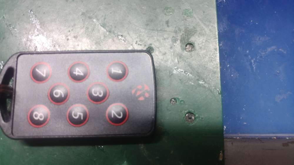
Did you buy a Fibaro keyfob has it fallen to pieces? well this might interest you. A eight keys keyfob ip68 ratedAnd here's the completed unit I have not really tested the range yet ,
but should be good , the receiver units (telemetry units) can work in latching mode and in push button mode easy
I am pretty sure this setup will last longer than fibrio key fob , easy to pair receiver with key fob
I have 3 key fobs ,, yes why ??? well they will break and I rather purchase few ,for an investment for the futureMaybe some can help me with other project the stamp m5 pico trying to program it is a standard switch node
https://forum.mysensors.org/topic/11886/and-for-my-next-trick-project-i-mean-m5stamp-pico-any-body-playing-with-these-yet-battery-operated-mp3-unit/2?_=1642356371902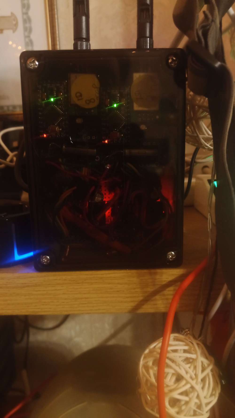
-
And for my next trick , Project I mean m5stamp pico any body playing with these yet ?? Battery operated mp3 unitWell managed to program m5stamp pico!!
looks like its the radio side that needs integrated, I did not hold outmuch chance it would work shame .
this coupled with some cmos fet transistors could be coupled to a DY-SV5W mp3 unit to play mp3 sounds
possibly battery powered too
Oh there seemed to be a problem Board install in Aurino ide , but was resolved by manually copying arduino-esp32-master.zip tools folder to the local tools folderMight be down pin assignments for radio , any help there would help
This could be a great board if it could be integrated as a mysensor node
-
And for my next trick , Project I mean m5stamp pico any body playing with these yet ?? Battery operated mp3 unitCheap units >>> m5stamp pico<<< and seem to be not so power draining , they do have a led but that can be removed to reduce power rain
Has any body tried programming these to work directly with mysensors ?? might try a Arduino ide compile for esp32
At present I have dumped Tasmoda firmware standard into one of theses units , and I am using a Model: DY-SV5W mp3 unit
I am planning on some smd cmos fet transistors on the outputs of the m5stamp to ground certain pins on the DY-SV5W , so that triggers playing different mp3 sound files in the SD card
A) what I will try,, but would really like to know is if this M5stamp pico can be directly connected to the mysensors network , ?? ( I can see ESP32 boards are supported in audrino IDE???)(with tasmoda it connects through a ip to your local wifi network , but with quite a few devices connecting thats a lot of ips taken up)
-
Did you buy a Fibaro keyfob has it fallen to pieces? well this might interest you. A eight keys keyfob ip68 ratedUpdate !!!! all fixed and working with domoticz
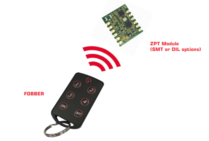
I used FOBBER-8T8 please google it approx. 20 quid compared to 45 pounds for fibaro keyfob
A) updated the sketch to allow 4 inputs s all fine
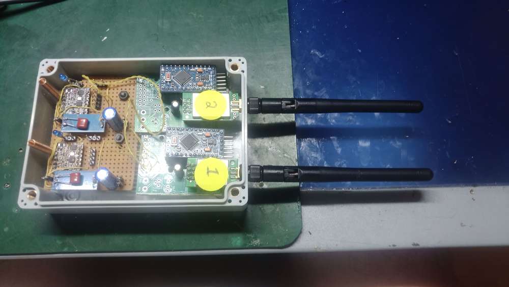
B) Symmetric really so from the top two pictures from the left the telemetry modules on the Vero board (total of 8 outputs ) passed across to two mysensors modules with 4 inputs on each unit I used 4016 cmos switches to pair outputs with inputs and It worked !!! .
So the ip 68 keyfob transmits to the telemetry modules which then output to the inputs of the sensors that
domoticz can pick up . add to blocky script can do what you want
Any help with This would be much applicated
https://forum.mysensors.org/topic/11886/and-for-my-next-trick-project-i-mean-m5stamp-pico-any-body-playing-with-these-yet-battery-operated-mp3-unit/2?_=1642356371902 -
Did you buy a Fibaro keyfob has it fallen to pieces? well this might interest you. A eight keys keyfob ip68 rated@mutantx
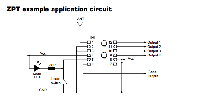
I am seeming to have problems with the sketch ,heres is the modified sketch any guidance appreciated ./** The MySensors Arduino library handles the wireless radio link and protocol between your home built sensors/actuators and HA controller of choice. The sensors forms a self healing radio network with optional repeaters. Each repeater and gateway builds a routing tables in EEPROM which keeps track of the network topology allowing messages to be routed to nodes. Created by Henrik Ekblad <henrik.ekblad@mysensors.org> Copyright (C) 2013-2015 Sensnology AB Full contributor list: https://github.com/mysensors/Arduino/graphs/contributors Documentation: http://www.mysensors.org Support Forum: http://forum.mysensors.org This program is free software; you can redistribute it and/or modify it under the terms of the GNU General Public License version 2 as published by the Free Software Foundation. ******************************* DESCRIPTION Simple binary switch example updated for 2 switches Connect button or door/window reed switch between digitial I/O pin 3 (BUTTON_PIN below) and GND. http://www.mysensors.org/build/binary */ // Enable debug prints to serial monitor #define MY_DEBUG // Enable and select radio type attached #define MY_RADIO_NRF24 //#define MY_RADIO_RFM69 #include <MySensors.h> #include <SPI.h> #include <Bounce2.h> #define CHILD_ID1 3 #define BUTTON_PIN1 3 // Arduino Digital I/O pin for button/reed switch #define CHILD_ID2 4 #define BUTTON_PIN2 4 // Arduino Digital I/O pin for button/reed switch #define CHILD_ID3 5 #define BUTTON_PIN3 5 // Arduino Digital I/O pin for button/reed switch #define CHILD_ID4 6 #define BUTTON_PIN4 6 // Arduino Digital I/O pin for button/reed switch Bounce debouncer1 = Bounce(); Bounce debouncer2 = Bounce(); // debouncer for the second switch Bounce debouncer3 = Bounce(); // debouncer for the third switch Bounce debouncer4 = Bounce(); // debouncer for the forth switch int oldValue1= -1; int oldValue2= -1; // second switch needs to have it's own old state int oldValue3= -1; // second switch needs to have it's own old state int oldValue4= -1; // second switch needs to have it's own old state // Change to V_LIGHT if you use S_LIGHT in presentation below MyMessage msg1(CHILD_ID1,V_TRIPPED),msg2(CHILD_ID2,V_TRIPPED),msg3(CHILD_ID3,V_TRIPPED),msg4(CHILD_ID4,V_TRIPPED); void setup() { // Setup the button pinMode(BUTTON_PIN1,INPUT_PULLUP ); // You can assign pinmode and use pullup in one statement. pinMode(BUTTON_PIN2,INPUT_PULLUP); pinMode(BUTTON_PIN3,INPUT_PULLUP); pinMode(BUTTON_PIN4,INPUT_PULLUP); // Activate internal pull-up // digitalWrite(BUTTON_PIN1,HIGH); // digitalWrite(BUTTON_PIN2,HIGH); // digitalWrite(BUTTON_PIN3,HIGH); // digitalWrite(BUTTON_PIN4,HIGH); // After setting up the button, setup debouncer1 debouncer1.attach(BUTTON_PIN1); debouncer1.interval(5); debouncer2.attach(BUTTON_PIN2); debouncer2.interval(5); debouncer3.attach(BUTTON_PIN3); debouncer3.interval(5); debouncer4.attach(BUTTON_PIN4); debouncer4.interval(5); // Register binary input sensor to gw (they will be created as child devices) // You can use S_DOOR, S_MOTION or S_LIGHT here depending on your usage. // If S_LIGHT is used, remember to update variable type you send in. See "msg" above. present(CHILD_ID1, S_DOOR); present(CHILD_ID2, S_DOOR); present(CHILD_ID3, S_DOOR); present(CHILD_ID4, S_DOOR); } // Check if digital input has changed and send in new value void loop() { // Check if the first switch state has changed debouncer1.update(); // Get the update value int value = debouncer1.read(); if (value != oldValue1) { // Send in the new value send(msg1.set(value==HIGH ? 1 : 0)); // send(msg2.set(value==HIGH ? 1 : 0)); // this is where you turn the second switch in your controller // send(msg3.set(value==HIGH ? 1 : 0)); // this is where you turn the third switch in your controller oldValue1 = value; } // Check if the 2nd switch state has changed debouncer2.update(); // Get the update value value = debouncer2.read(); // no need to redeclare it (I removed int) if (value != oldValue2) { // Send in the new value // send(msg1.set(value==HIGH ? 1 : 0)); send(msg2.set(value==HIGH ? 1 : 0)); // this is where you turn the second switch in your controller // send(msg3.set(value==HIGH ? 1 : 0)); // this is where you turn the third switch in your controller oldValue2 = value; } // Check if the third switch state has changed debouncer3.update(); // Get the update value value = debouncer3.read(); // no need to redeclare it (I removed int) if (value != oldValue3) { // Send in the new value // send(msg1.set(value==HIGH ? 1 : 0)); // send(msg2.set(value==HIGH ? 1 : 0)); // this is where you turn the second switch in your controller send(msg3.set(value==HIGH ? 1 : 0)); // this is where you turn the third switch in your controller oldValue3 = value; } // Check if the forth switch state has changed debouncer4.update(); // Get the update value value = debouncer4.read(); // no need to redeclare it (I removed int) if (value != oldValue4) { // Send in the new value // send(msg1.set(value==HIGH ? 1 : 0)); // send(msg2.set(value==HIGH ? 1 : 0)); // this is where you turn the second switch in your controller send(msg4.set(value==HIGH ? 1 : 0)); // this is where you turn the forth switch in your controller oldValue4 = value; } } -
Did you buy a Fibaro keyfob has it fallen to pieces? well this might interest you. A eight keys keyfob ip68 ratedHi fellow mysensors people :)
I have been working on a project , might need a bit of guidance to finish this off (with the sketch)
Ok lets start with what I have been doing , plus some researchingRight who of you purchased Fibaro_keyfob ??? that very reliable and ruggedized key fob
well yes I did too , it was approx. 45 pounds how long did it last ?? hmm 12 months or so
you also need a Aeotec_z-stick_gen5 to link it to domoticz .It might look nice,, but really in my option was not fit for purpose poor design
at high price !!!.
The Fibaro you have to use a large coin to open and replace the battery ,,,,the connectors inside well weak!! not long and its buggered .. oh I’ll go and buy another at 45 ponds naaaaa!!!!
rinse and repeat every 12 months or so naaaa!!!!
you also needed a Aeotec_z-stick_gen5 to connect to domoitcz. As said.Why would I do this since nowhere days we have voice control etc..
well for me it’s a universal way of switching off quite few things at once etc,,So what was the alternative’s ???? ok
Well firstly most key fobs I have found are only 4 keys I wanted few more than that
in the end I came up with the key fob in first picture a ( rf solutions) key fob ip68 rated helpful might last past 12 months ,ok , now at this point I thought oh err use rflink to pick up signals job done But naaa it does not sense them , so if you want try this then rflick is not ganna cut it unfortunately .
So then you need its receiver module ie ..>>>
Telemetry module that in my case at 443mz frequency . be sure to get a receiver module that matches the key fobs transmitting frequency ( I did not need to tell you that did I :) )
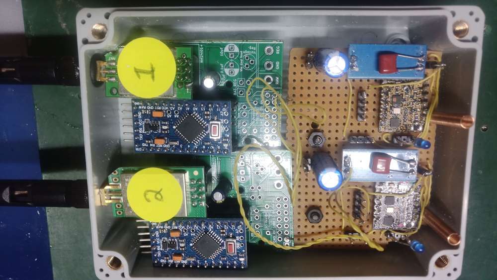
Ok so the second picture is of the receiver module really not that hard really!!! .
My soldering will just about passes put quite a few caps in to stabilise the power as best as possible .
As you can see the telemetry modules are on the left and the mysensors (2) on the right .
I picked up a program from another project and modified it so that hopefully it would pick up four inputs on each unit
mini pro The sketch presented here is the modified sketch with 4 inputs
but one input works and the other inputs are temperamental
any suggestions or guidance for interfacing this with modules would be nice .** Oh these receiver units like 3.6 volts so keep the voltage down
roughly 33 quid for key fob
11 pounds for each receiver unit ,,,you will need 2 for the eight key fob unit
 image url))

-
help pleaseHi ,, yes I see that but you have too very closely to see were the green lines go on the breadboard . hoping I get it right ,
May I ask one last question please
Commands must be sent as V_VAR1 ? not too sure how to do this , I can see the child
options I think here
0 S_UNKNOWN true 1200 -
1 S_RGBW_LIGHT RGBW test light true 1200 -
69 S_UNKNOWN true 1200 -
255 S_ARDUINO_NODE 1.5.4 false 1200 -
just not sure who start it play a mp3 ? any help much appreciatedThe DFPlayerBat node implements two children
interface to DFPlayer
This child is of type S_CUSTOM. Commands must be sent as V_VAR1. Answers from the DFPlayer are sent to the controller as V_VAR2. V_VAR3 is the sleep time in milli seconds. 2. RGB-LEDThe three color pins are connected to PWM outputs of the Arduino, i.e. each color intensity can be set in 256 steps. This child is of type S_RGB_LIGHT and expects a value as V_RGB.
-
help pleaseRe: 💬 MP3 player with RGB-signal LED (optionally battery powered)
Re: 💬 MP3 player with RGB-signal LED (optionally battery powered)
I want to use this for some space 1999 unit around the house it would be great if the
circuit diagram please
was available please , just o clarify the battery side of things .
How do we send asci text to the unit as well please ?? want to pop some sound effect on the sd card ,, yes yes space1999 sound effects -
yes if the creator is still around Please could you possibly give a circuit diagram please just clear things upRe: 💬 MP3 player with RGB-signal LED (optionally battery powered)
I want to use this for some space 1999 unit around the house it would be great if the
circuit diagram please
was available please , just o clarify the battery side of things .
How do we send asci text to the unit as well please ?? want to pop some sound effect on the sd card ,, yes yes space1999 sound effects -
Smart Pantry ,something to be adapted for Mysensors Domdoticz at least the wife wont mone :)Just a suggestion ,anybody seen this looks quite interesting
https://www.instructables.com/id/Smart-Pantry/
maybe this can be adapted for domoticz and mysensors
Well at least if your low on onions ,your not ganna get the " did you get the onions " Question when you get back from shopping
I don't know,,, maybe it's me .. looks promising
-
💬 Smart(ish) LED Strip [Non-Addressable]Damm I am trying to get this working with a Arduino pro mini ,,but no luck wanted to use it in the car ..
How do you wire the NRF24L01+ ???
N-Channel Mosfet s ??? model number please any help much appreciated
I have tried mosfets >>>irf510n -
💬 Soil Moisture SensorHenrik
Yes could you please confirm how the nano is connected to the sensors ,soil sensors please ,yes 5+ 0- pin 3 ?? or in your sketch pin 6 7 ? to were
or a0 a1 please how?? pin 6 to pin 3 on nano ?? it just not clear ?? -
Arduino-controlled-battery-charger AND Amazon DOT control VA DomoticzTwo projects I am looking at present ..I take No credit for any of this work, it is other peoples project out there on the internet ,but I must say Quite interesting ,,so here we go
Amazon dot (echo as well)
I thought it would be worth mentioning here, since it works quite well with Domotciz and mysensor units ,and you other guys might like to try it.
Check out this URL
http://www.makermusings.com/2015/07/18/virtual-wemo-code-for-amazon-echo/
I have run the python script on the raspberry PI 2 and adjusted the Json script to switch lights of and on ,works well (Up to 16 units)
Arduino-controlled-battery-charger
This project by some one out there is about the only standard charger for non lipo Batteries I have found
( I am sure other people will now mention others,, please do)
here is the URL
http://www.allaboutcircuits.com/projects/create-an-arduino-controlled-battery-charger/
you can monitor the serial out to see how well it is charging
I thought about adding this WiFi to Serial Bridge, Arduino, RPi, ByPic
ebay item number 311554685109
It would really nice ,if some one could add a LCD to the sketch +++ some buttons so the charge could be adjusted OR it could made in to mysensor for Domoticz
Some one has tried to duplicate the charging circuit for 4 batteries ,but the developer has said there would not be enough inputs for the temperature sensing of 4 batteriesOh and Merry Christmas everybody ,Happy new year :) have a mince pie on me .
-
IR Infrared reflectance sensor arduino sensor shield 5v DC (sence Who is what room),security tooWell its been a bit of time and my home automation system with Domoticz is great !!
with the great guys here allowing us to make sensors that would cost a lot more if it were a commercial product ,,Thank you all again to all the great work.here .
Right lets get on ,well I have been testing these reflectance sensors ,they are only approx 3 pound each on Ebay .I have combined them with a multi-sensor sketch ,I have given a link to the item below plus a screen shot of my floor-plan with in Domoticz .I am thinking along the lines of one inside the door and some in the hallway then when you move say from front room to kitchen it would trigger sensors front-room hallway then kitchen ,hmmm .that coupled with some PIR sensors might do the trick,they have a range about 36 inches ,so pop the by the door or in the ceiling (ceiling for me) .very easy to setup they run off 5volts I use pro mini 3.3 volt
link to sensor I am sure you have seen them out there
http://www.ebay.co.uk/itm/182262409855?_trksid=p2057872.m2749.l2649&ssPageName=STRK%3AMEBIDX%3AIT


along g
-
Wall Switches Solid State relay 1cm SquareBecause these Switch power on ,off at the zero voltage point .
Dimming is not possible ,I think ,
One thing it does not need power ,you just connect pin 3 to low voltage side (opt-isolated)
High voltage side just run live line through it . -
Office plant monitoringThought I would throw this in the pot
Why not change the sensor Probe ?? no credit to me , just was googleing as you do,
Home made sensors I think less prone to corrosion
here's the linkhttp://www.cheapvegetablegardener.com/how-to-make-cheap-soil-moisture-sensor-2/
Had some seeds from very tasty tomatoes last year ,have planted and this year growing like tiffids !!
Getting quite big so have move from kitchen to Greenhouse ASP really
Will try with this type of sensor -
Wall Switches Solid State relay 1cm SquareI think depends were you are around the world ,,as to how available it is .I live in the UK ,the was some other people who were using this in there project ,there was company supplying here ,but the had a fixed postage and packing of £12 !!! ,so it made it a bit silly ordering small mounts ,,but Farnell electronics are much better if your order is over £20 Free delivery .Here's the link
http://uk.farnell.com/sharp/pr39mf51yipf/relay-solid-state/dp/1618487RL
to the parts I ordered .As you can see 190 Watts max ,I have tried with florescent lights and it is fine .
NO Switching noise relays click these noooo noise :)
Zero Voltage switching This were the the circuit switches power on or off at the point were the Ac wave cross's zero ,
The result no interference when switching on or off (voltage spikes)
Relays don,t have that ability.(Some one going to prove me wrong )I ordered 14 of them cost just over £20 ,(free delivery) I needed 9 for wall switch's ,,( so some pare )
And only 1cm square !!
All you have to do is connect pin3 from the Relay sensor Plus ground
This unit really is easy to connect to relat switching unit
PLEASE do remember you are dealing the MAINS power ,if you love LIFE be careful High voltages KIll !! -
Wall Switches Solid State relay 1cm SquareI hope this is in the right Place , please feel free to a move to better topic if needed.
First things first I would like to say a BIG thank you for this great site and ,Bruce Lacey,Henrik Ekblad,Olivier ,Mauti,Thomas Bowman Mørch,Pete Will,Patrick Fallberg and all other contributors .I am converted .
I have Domoticz with quite a few sensors .
I Promise once I am bit more solvent ,I will donate ,(at present no job).
I’ll get to the point maybe some ones already investigated this ,but here we go
wall lights a relays .Well relays can take up a bit of space ,well this seems like good alternate ,
With Zero voltage switching .
Measuring 1 cm square ,interested ??
Manufacturer: SHARP
Order Code: 1618487
Manufacturer Part No PR39MF51YIPFMade by Sharp 39MF22 7 pin package <<Google it
Well there did seems to be a bit of problem over here in the UK since ordering one would incur a £12 postage some company had a fixed postage for any order, making it silly to order unless you were ordering a crate .
I did some googleing and found Farnell components a much better bet .
I have tried tested 39MF22 with the relay Sketch, I did not add a snubber circuit ,but for me it works well.
I was using X10 equipment before ,soon I will be changing all wall switch’s to Micro Nano plus a 39MF22 etc. with thelimited available space ,it looks like I will be able gut the old X10 switch’s and replace with new electronics .
There may be a issue with RF interference with component’s being in close proximity But as for me this works well withZero voltage switching a nice touch .
If you push me kick me,, I might put up some pictures of the converted X10 wall switch ,won’t be too pretty but might giveyou some ideas .
Oh it seems to work fine with florescent lighting (tested) .
The 39MF22 can handle 900mA and has an isolation voltage of 4kV
Max Power just under 200 watt ,I believeManufacturer: SHARP
Order Code: 1618487
Manufacturer Part No PR39MF51YIPF